EP3501655B1 - Sample distribution system and method for distributing samples - Google Patents
Sample distribution system and method for distributing samples Download PDFInfo
- Publication number
- EP3501655B1 EP3501655B1 EP18215662.0A EP18215662A EP3501655B1 EP 3501655 B1 EP3501655 B1 EP 3501655B1 EP 18215662 A EP18215662 A EP 18215662A EP 3501655 B1 EP3501655 B1 EP 3501655B1
- Authority
- EP
- European Patent Office
- Prior art keywords
- sensor unit
- pipette tips
- pipette
- unit
- light
- Prior art date
- Legal status (The legal status is an assumption and is not a legal conclusion. Google has not performed a legal analysis and makes no representation as to the accuracy of the status listed.)
- Active
Links
- 238000000034 method Methods 0.000 title claims description 44
- 238000001514 detection method Methods 0.000 claims description 32
- 230000004888 barrier function Effects 0.000 claims description 7
- 108010076504 Protein Sorting Signals Proteins 0.000 claims description 6
- 230000001154 acute effect Effects 0.000 claims description 6
- 230000003213 activating effect Effects 0.000 claims description 3
- 230000008859 change Effects 0.000 claims description 3
- 238000006073 displacement reaction Methods 0.000 claims description 3
- 230000008569 process Effects 0.000 description 16
- 239000007788 liquid Substances 0.000 description 12
- 239000002699 waste material Substances 0.000 description 12
- 238000011161 development Methods 0.000 description 10
- 230000018109 developmental process Effects 0.000 description 10
- 238000012360 testing method Methods 0.000 description 10
- 230000007246 mechanism Effects 0.000 description 8
- 238000011156 evaluation Methods 0.000 description 6
- 238000012544 monitoring process Methods 0.000 description 4
- 238000011109 contamination Methods 0.000 description 3
- 238000012864 cross contamination Methods 0.000 description 2
- 230000001419 dependent effect Effects 0.000 description 2
- 238000005259 measurement Methods 0.000 description 2
- 238000005457 optimization Methods 0.000 description 2
- 230000004913 activation Effects 0.000 description 1
- 238000005352 clarification Methods 0.000 description 1
- 238000013461 design Methods 0.000 description 1
- 238000003780 insertion Methods 0.000 description 1
- 230000037431 insertion Effects 0.000 description 1
- 238000012545 processing Methods 0.000 description 1
- 208000008918 voyeurism Diseases 0.000 description 1
Images

Classifications
-
- G—PHYSICS
- G01—MEASURING; TESTING
- G01N—INVESTIGATING OR ANALYSING MATERIALS BY DETERMINING THEIR CHEMICAL OR PHYSICAL PROPERTIES
- G01N35/00—Automatic analysis not limited to methods or materials provided for in any single one of groups G01N1/00 - G01N33/00; Handling materials therefor
- G01N35/10—Devices for transferring samples or any liquids to, in, or from, the analysis apparatus, e.g. suction devices, injection devices
- G01N35/1065—Multiple transfer devices
-
- B—PERFORMING OPERATIONS; TRANSPORTING
- B01—PHYSICAL OR CHEMICAL PROCESSES OR APPARATUS IN GENERAL
- B01L—CHEMICAL OR PHYSICAL LABORATORY APPARATUS FOR GENERAL USE
- B01L3/00—Containers or dishes for laboratory use, e.g. laboratory glassware; Droppers
- B01L3/02—Burettes; Pipettes
- B01L3/021—Pipettes, i.e. with only one conduit for withdrawing and redistributing liquids
- B01L3/0213—Accessories for glass pipettes; Gun-type pipettes, e.g. safety devices, pumps
-
- B—PERFORMING OPERATIONS; TRANSPORTING
- B01—PHYSICAL OR CHEMICAL PROCESSES OR APPARATUS IN GENERAL
- B01L—CHEMICAL OR PHYSICAL LABORATORY APPARATUS FOR GENERAL USE
- B01L3/00—Containers or dishes for laboratory use, e.g. laboratory glassware; Droppers
- B01L3/02—Burettes; Pipettes
- B01L3/0275—Interchangeable or disposable dispensing tips
-
- B—PERFORMING OPERATIONS; TRANSPORTING
- B01—PHYSICAL OR CHEMICAL PROCESSES OR APPARATUS IN GENERAL
- B01L—CHEMICAL OR PHYSICAL LABORATORY APPARATUS FOR GENERAL USE
- B01L3/00—Containers or dishes for laboratory use, e.g. laboratory glassware; Droppers
- B01L3/02—Burettes; Pipettes
- B01L3/021—Pipettes, i.e. with only one conduit for withdrawing and redistributing liquids
- B01L3/0217—Pipettes, i.e. with only one conduit for withdrawing and redistributing liquids of the plunger pump type
- B01L3/0237—Details of electronic control, e.g. relating to user interface
-
- G—PHYSICS
- G01—MEASURING; TESTING
- G01N—INVESTIGATING OR ANALYSING MATERIALS BY DETERMINING THEIR CHEMICAL OR PHYSICAL PROPERTIES
- G01N21/00—Investigating or analysing materials by the use of optical means, i.e. using sub-millimetre waves, infrared, visible or ultraviolet light
- G01N21/17—Systems in which incident light is modified in accordance with the properties of the material investigated
- G01N21/55—Specular reflectivity
- G01N21/552—Attenuated total reflection
- G01N21/553—Attenuated total reflection and using surface plasmons
-
- G—PHYSICS
- G01—MEASURING; TESTING
- G01N—INVESTIGATING OR ANALYSING MATERIALS BY DETERMINING THEIR CHEMICAL OR PHYSICAL PROPERTIES
- G01N35/00—Automatic analysis not limited to methods or materials provided for in any single one of groups G01N1/00 - G01N33/00; Handling materials therefor
- G01N35/00584—Control arrangements for automatic analysers
-
- G—PHYSICS
- G01—MEASURING; TESTING
- G01N—INVESTIGATING OR ANALYSING MATERIALS BY DETERMINING THEIR CHEMICAL OR PHYSICAL PROPERTIES
- G01N35/00—Automatic analysis not limited to methods or materials provided for in any single one of groups G01N1/00 - G01N33/00; Handling materials therefor
- G01N35/10—Devices for transferring samples or any liquids to, in, or from, the analysis apparatus, e.g. suction devices, injection devices
- G01N35/1081—Devices for transferring samples or any liquids to, in, or from, the analysis apparatus, e.g. suction devices, injection devices characterised by the means for relatively moving the transfer device and the containers in an horizontal plane
- G01N35/109—Devices for transferring samples or any liquids to, in, or from, the analysis apparatus, e.g. suction devices, injection devices characterised by the means for relatively moving the transfer device and the containers in an horizontal plane with two horizontal degrees of freedom
-
- B—PERFORMING OPERATIONS; TRANSPORTING
- B01—PHYSICAL OR CHEMICAL PROCESSES OR APPARATUS IN GENERAL
- B01L—CHEMICAL OR PHYSICAL LABORATORY APPARATUS FOR GENERAL USE
- B01L2200/00—Solutions for specific problems relating to chemical or physical laboratory apparatus
- B01L2200/14—Process control and prevention of errors
- B01L2200/143—Quality control, feedback systems
-
- G—PHYSICS
- G01—MEASURING; TESTING
- G01N—INVESTIGATING OR ANALYSING MATERIALS BY DETERMINING THEIR CHEMICAL OR PHYSICAL PROPERTIES
- G01N35/00—Automatic analysis not limited to methods or materials provided for in any single one of groups G01N1/00 - G01N33/00; Handling materials therefor
- G01N35/00584—Control arrangements for automatic analysers
- G01N35/00722—Communications; Identification
- G01N35/00732—Identification of carriers, materials or components in automatic analysers
- G01N2035/00742—Type of codes
- G01N2035/00772—Type of codes mechanical or optical code other than bar code
Description
Die Erfindung betrifft ein Probenverteilsystem gemäss Oberbegriff des Anspruchs 1 sowie ein Verfahren zur Verteilung von Proben gemäss Oberbegriff des Anspruch 10.The invention relates to a sample distribution system according to the preamble of claim 1 and a method for distributing samples according to the preamble of
Probenverteilsystems sind aus dem Stand der Technik bekannt und diese werden typischerweise in Laboren verwendet. Diese Probenverteilsysteme arbeiten meist mit Pipetten, die zum Dosieren von Flüssigkeiten dienen. Es gibt automatisierte Pipettensysteme und handgehaltene und/oder handbedienbare Pipetten. Alle diese Geräte weisen einen Probenbehälter auf, in welchen eine meist flüssige, zu pipettierende Probe aufgenommen und aus welchem diese wieder abgegeben werden kann.Sample distribution systems are known in the art and are typically used in laboratories. These sample distribution systems usually work with pipettes that are used to dose liquids. There are automated pipette systems and hand-held and/or hand-operated pipettes. All of these devices have a sample container in which a mostly liquid sample to be pipetted is received and from which it can be released again.
Die Aufnahme und Abgabe einer Probe kann beispielsweise dadurch erreicht werden, dass im Probenbehälter zur Aufnahme der Probe ein Unterdruck und zur Abgabe der Probe ein Überdruck erzeugt wird. Kolbenhubpipetten besitzen zu diesem Zweck beispielsweise einen beweglichen Kolben, wobei zwischen der zu pipettierenden Probe und dem Kolben eine Luftsäule angeordnet ist. Bei Bewegung des Kolbens in eine erste Richtung verdrängt der Kolben die Luftsäule, während er bei Bewegung in eine der ersten Richtung entgegengesetzte zweite Richtung die Luftsäule und damit auch die zu pipettierende Probe in den Probenbehälter zieht.A sample can be taken up and released by, for example, generating a negative pressure in the sample container to take up the sample and an overpressure to release the sample. For this purpose, piston pipettes have, for example, a movable piston, with an air column being arranged between the sample to be pipetted and the piston. When the piston moves in a first direction, the piston displaces the air column, while when it moves in a second direction opposite to the first direction, it pulls the air column and thus also the sample to be pipetted into the sample container.
Um eine Kontamination zu vermeiden, können Pipetten mit auswechselbaren Probenbehältern in der Form von Pipettenspitzen ausgerüstet sein. Die Pipette verfügt dann über einen Verbindungsabschnitt, auf den die Pipettenspitze aufgesteckt und von dem sie nach Gebrauch wieder entfernt werden kann. Die Pipettenspitze weist üblicherweise zwei Öffnungen auf, wobei der Verbindungsabschnitt beim Aufstecken in die grössere der beiden Öffnungen aufgenommen wird und diese verschliesst. Die Aufnahme und Abgabe der Probe erfolgt durch die kleinere Öffnung. Da nur die Pipettenspitze mit der zu pipettierenden Probe in Berührung kommt, ist eine Kontamination bei nachfolgenden Pipettiervorgängen verhindert. Die Pipettenspitze ist üblicherweise ein Wegwerfartikel aus Kunststoff.In order to avoid contamination, pipettes can be equipped with exchangeable sample containers in the form of pipette tips. The pipette then has a connecting section onto which the pipette tip can be placed and from which it can be removed again after use. The pipette tip usually has two openings, with the connecting section being received in the larger of the two openings and closing it when it is pushed on. The sample is taken up and released through the smaller opening. Since only the pipette tip comes into contact with the sample to be pipetted, contamination during subsequent pipetting processes is prevented. The pipette tip is usually a disposable plastic item.
Neben den rein mechanischen existieren auch elektronisch gesteuerte Pipetten. Ausserdem können Pipetten einen (bei Einkanalpipetten) oder mehrere (bei Mehrkanalpipetten) Verbindungsabschnitte aufweisen. Mehrere Verbindungsabschnitte, die jeweils mit einer wechselbaren Pipettenspitze bestückt werden können, erlauben das gleichzeitige Aufnehmen und Abgeben mehrerer Proben. Die zum Einsatz kommenden Abwurfmechanismen besitzen üblicherweise einige Gemeinsamkeiten. Dazu gehört ein Schieber, der entlang des Verbindungsabschnitts beweglich ausgebildet ist. Bei Betätigung des Abwurfmechanismus wird der Schieber in Richtung der Pipettenspitze bewegt, tritt mit dieser in Kontakt und schiebt sie entgegen der Aufsteckrichtung vom Verbindungsabschnitt. Oftmals ist der Abwurfmechanismus mittels eines Bedienelements von Hand betätigbar. Es sind jedoch auch automatisierte Abwurfmechanismen bekannt, welche beispielsweise durch elektrische oder pneumatische Antriebe betrieben werden. In jedem Fall wird dabei eine Kraft mechanisch auf den Schieber übertragen, um so dessen Bewegung in Richtung der Pipettenspitze zu bewirken. Der Teil des Abwurfmechanismus, der die Verbindung zwischen Bedienelement oder Antrieb und Schieber herstellt, kann unterschiedlich ausgestaltet sein, weist jedoch im Allgemeinen ein oder mehrere bewegliche Glieder auf. Die Bewegung der Glieder ist mit der Bewegung des Schiebers gekoppelt. Zweckmässigerweise sind die Glieder zur Übertragung der beim Betätigen auf das Bedienelement ausgeübten Kraft oder der durch den Antrieb ausgebübten Kraft auf den Schieber ausgebildet.In addition to the purely mechanical pipettes, there are also electronically controlled pipettes. In addition, pipettes can have one (in the case of single-channel pipettes) or several (in the case of multi-channel pipettes) connecting sections. Several connecting sections, each of which can be equipped with an exchangeable pipette tip, allow several samples to be taken up and dispensed at the same time. The release mechanisms used usually have some things in common. This includes a slider that is designed to be movable along the connecting section. When the ejection mechanism is actuated, the slide is moved in the direction of the pipette tip, comes into contact with it and pushes it off the connecting section in the opposite direction to the push-on direction. The ejection mechanism can often be actuated manually by means of an operating element. However, automated release mechanisms are also known, which are operated, for example, by electrical or pneumatic drives. In any case, a force is mechanically transmitted to the slide in order to cause its movement in the direction of the pipette tip. The part of the ejector mechanism that makes the connection between the control or drive and the pusher can be designed in a variety of ways, but generally has one or more movable members. The movement of the links is linked to the movement of the slide. The members are expediently designed to transmit the force exerted on the operating element when it is actuated or the force exerted by the drive on the slide.
Insbesondere bei automatisierten Probenverteilsystemen, wie beispielsweise Pipettierrobotern mit automatischen Abwurfmechanismen für die Pipettenspitzen ist es bekannt, den erfolgten Abwurf durch spezielle, mechanisch ausgeführte und im Bereich des Verbindungsabschnittes angebrachte Sensoren zu überwachen. Hierzu ist in der Regel direkt im Bereich des Verbindungsabschnittes zwischen Pipettiereinheit und Pipettenspitze ein Schieber und ein Sensor angeordnet, mit deren Hilfe die Anwesenheit einer Pipettenspitze gemessen wird. Pro Pipettenspitze ist folglich eine eigene Messeinheit notwendig, um den Abwurf zu überwachen. Weiters ist ein häufiges Problem beim Abwurf der Pipettenspitzen, dass diese zwar vom Verbindungsabschnitt gelöst werden, aber nicht vollständig abfallen, weil diese beispielsweise durch elektrostatisehe Kräfte hängen bleiben. Solche hängen gebliebenen Pipettenspitzen sind für die bekannten mechanischen Sensoren nicht erkennbar. Der ordnungsgemässe Abwurf der Pipettenspitzen und damit die korrekte Überwachung dieses Vorgangs ist generell für das Pipettieren eine kritische Funktion. Wenn nämlich kontaminierte Pipettenspitzen das Pipettierdeck mit den Proben berühren, müssen alle zuvor gemachten Proben bzw. Ergebnisse als hinfällig betrachtet werden.Particularly in the case of automated sample distribution systems, such as pipetting robots with automatic ejection mechanisms for the pipette tips, it is known to monitor the ejection that has taken place using special, mechanically designed sensors mounted in the area of the connecting section. For this purpose, a slide and a sensor are usually arranged directly in the region of the connecting section between the pipette unit and the pipette tip, with the aid of which the presence of a pipette tip is measured. A separate measuring unit is therefore required for each pipette tip in order to monitor the ejection. Furthermore, a frequent problem when dropping the pipette tips is that although they are detached from the connecting section, they do not fall off completely because they are caused by electrostatic forces, for example forces get stuck. Such stuck pipette tips cannot be detected by the known mechanical sensors. The correct ejection of the pipette tips and thus the correct monitoring of this process is a critical function for pipetting in general. If contaminated pipette tips touch the pipette deck with the samples, all previously made samples or results must be considered invalid.
Die
Die
Es ist deshalb eine Aufgabe der vorliegenden Erfindung, ein verbessertes Probenverteilsystem und ein verbessertes Verfahren zum Verteilen von Proben bereitzustellen. Hierbei soll insbesondere der Abwurfmechanismus in der Weise verbessert werden, dass der ordnungsgemässe Abwurf der Pipettenspitzen zuverlässig überwacht werden kann und dementsprechend Fehler beim Abwurf zuverlässig erkannt werden können. Gelöst wird diese Aufgabe durch ein Probenverteilsystem mit den Merkmalen des Anspruch 1. Vorteilhafte Ausgestaltungen werden in den abhängigen Ansprüchen 2-9 beschrieben. Weiters wird diese Aufgabe durch ein Verfahren mit den Merkmalen des Anspruch 10 gelöst. Vorteilhafte Ausgestaltungen des Verfahrens sind in den abhängigen Ansprüchen 11-15 beschrieben.It is therefore an object of the present invention to provide an improved sample dispensing system and method for dispensing samples. In particular, the ejection mechanism is to be improved in such a way that the correct ejection of the pipette tips can be reliably monitored and accordingly errors during ejection can be reliably detected. This object is achieved by a sample distribution system having the features of claim 1. Advantageous refinements are described in the dependent claims 2-9. Furthermore, this object is achieved by a method having the features of
Unter Pipettiervorgang ist die Aufnahme insbesondere einer Flüssigkeit in Pipetten und die Verteilung bzw. Abgabe der Flüssigkeit auf einem Probenbehälter zu verstehen, welcher in der Regel eine Vielzahl von kleinen Töpfen aufweist.The pipetting process is to be understood as meaning the taking up, in particular, of a liquid in pipettes and the distribution or dispensing of the liquid on a sample container, which generally has a large number of small pots.
Das erfindungsgemässe Probenverteilsystems und das erfindungsgemässe Verfahren sind in der Lage quasi von aussen auf die Pipettiereinheit zu blicken und können daher in vorteilhafter Weise ermitteln, ob eine Pipettenspitze ordnungsgemäss abgeworfen wurde oder nicht. Ausserdem ist es möglich zu überwachen, ob eine Pipettenspitze fehlt bzw. ob alle Pipettenspitzen vorhanden sind, das heisst, ob alle Pipettenspitze ordnungsgemäss aus einem Vorratsbehälter für Pipettenspitzen aufgenommen wurden. Ausserdem kann die Form und die Lage der Pipettenspitzen insbesondere relativ zur Pipettiereinheit geprüft werden.The sample distribution system according to the invention and the method according to the invention are able to look at the pipetting unit from the outside and can therefore advantageously determine whether a pipette tip has been properly ejected or not. In addition, it is possible to monitor whether a pipette tip is missing or whether all pipette tips are present, ie whether all pipette tips have been properly picked up from a storage container for pipette tips. In addition, the shape and position of the pipette tips can be checked, in particular relative to the pipette unit.
In einer ersten Ausführungsform der Erfindung sind die Sensoreinheit und die Pipettiereinheit relativ zueinander beweglich ausgeführt, um auf das Vorhandensein einer Pipettenspitze zu schliessen, wenn sich diese im Detektionsbereich der Sensoreinheit befindet.In a first embodiment of the invention, the sensor unit and the pipette unit are designed to be movable relative to one another in order to determine the presence of a pipette tip when this is located in the detection area of the sensor unit.
Der Sensoreinheit kann ein Zähler zugeordnet sein, um die Anzahl der Pipettenspitzen zu ermitteln. Der Detektionsbereich der Sensoreinheit ist im einfachsten Fall durch einen einzigen Lichtstrahl oder Lichtpuls gebildet. Möglich wäre aber auch der Einsatz von Lichtschranken, die als Lichtgitter ausgebildet sind und die eine Mehrzahl an Lichtstrahlen zur Detektion verwenden. Zu beachten ist, dass mit dem Lichtstrahl die einzelnen Pipettenspitzen abgetastet werden, d.h. der Lichtstrahl wird relativ zu den Pipettenspitzen bewegt. Trifft beispielsweise der Lichtstrahl direkt auf eine Pipettenspitze, wird der Strahl nicht zurückreflektiert und es entsteht eine für den Sensor detektierbare Dunkelstelle. Aus der Anzahl der detektierten Dunkelstellen kann daher auf die Anzahl der vorhandenen Pipettenspitzen geschlossen werden. Die exakte Auswertung erfolgt in an sich bekannter Weise mittels entsprechender Verarbeitungsalgorithmen.A counter can be assigned to the sensor unit in order to determine the number of pipette tips. In the simplest case, the detection area of the sensor unit is formed by a single light beam or light pulse. However, it would also be possible to use light barriers which are designed as light grids and which use a plurality of light beams for detection. It should be noted that the individual pipette tips are scanned with the light beam, i.e. the light beam is moved relative to the pipette tips. For example, if the light beam hits a pipette tip directly, the beam is not reflected back and a dark spot is created that can be detected by the sensor. The number of pipette tips present can therefore be deduced from the number of dark spots detected. The exact evaluation takes place in a manner known per se using appropriate processing algorithms.
In einer weiteren Ausführungsform ist die Sensoreinheit verschwenkbar gelagert, um den Detektionsbereich um die Z-Achse aus einer Startposition in eine Endposition zu verschwenken. Alternativ dazu kann die Sensoreinheit derart verbaut sein, dass die Hauptrichtung des Detektionsbereichs mit der Bewegungsrichtung entlang der X-Achse der Stellvorrichtung einen spitzen Winkel bildet.In a further embodiment, the sensor unit is pivotably mounted in order to pivot the detection area around the Z-axis from a start position to an end position. Alternatively, the sensor unit can be installed in such a way that the Main direction of the detection area with the direction of movement along the X-axis of the actuator forms an acute angle.
Die Sensoreinheit kann ortsunveränderlich bezüglich Grundplatte und somit gegenüber der Behälter im oder am Probenverteilsystem verbaut sein.The sensor unit can be fixed in place with respect to the base plate and thus in relation to the container in or on the sample distribution system.
Die Sensoreinheit weist in einer Ausführungsform der Erfindung eine Laserdiode zum Aussenden von Lichtpulsen oder Lichtstrahlen und insbesondere eine vor der Laserdiode angeordnete Optik auf, wobei der Lichtpuls oder Lichtstrahl einen Strahldurchmesser aufweist, der kleiner als die kleinste Pipettenspitze an ihrer schmalsten Stelle breit ist. Der Strahldurchmesser definiert folglich die erzielbare Auflösung der Sensoreinheit und muss entsprechend der Kleinheit der Messobjekts - also der Pipettenspitze - gewählt werden.In one embodiment of the invention, the sensor unit has a laser diode for emitting light pulses or light beams and, in particular, optics arranged in front of the laser diode, the light pulse or light beam having a beam diameter that is smaller than the width of the smallest pipette tip at its narrowest point. The beam diameter consequently defines the achievable resolution of the sensor unit and must be selected according to the small size of the measurement object - i.e. the pipette tip.
Vorzugsweise wird die Pipettenspitze nicht beim Bereich des Verbindungsabschnittes detektiert, sondern man ist bestrebt die Überlappung des Detektionsbereichs mit dem schmalen bzw. spitzen Bereich der Pipettenspitze - also mit dem Bereich mit der kleinen Öffnung der Pipettenspitze - zu erkennen. Um hier möglichst schmale Pipettenspitzen erkennen zu können, ist es von Vorteil einen Lichtstrahl mit möglichst kleinem Strahldurchmesser zu verwenden.Preferably, the pipette tip is not detected in the area of the connecting section, but the attempt is made to detect the overlapping of the detection area with the narrow or pointed area of the pipette tip—ie with the area with the small opening of the pipette tip. In order to be able to recognize pipette tips that are as narrow as possible, it is advantageous to use a light beam with the smallest possible beam diameter.
Die Sensoreinheit kann so ausgeführt sein, dass sie mit einem Reflektorelement zusammenwirkt, welches am Öffnungsrand wenigstens eines der Behälter angeordnet ist und Lichtstrahlen oder Lichtpulse in Richtung dieses Reflektorelementes aussendet. Hierbei kann das Reflektorelement unmittelbar an den Behälter angebaut sein oder an einem separaten Halter montiert sein.The sensor unit can be designed in such a way that it interacts with a reflector element which is arranged at the edge of the opening of at least one of the containers and emits light beams or light pulses in the direction of this reflector element. Here, the reflector element can be attached directly to the container or mounted on a separate holder.
Die Sensoreinheit ist beispielsweise so angeordnet, dass diese den Detektionsbereich über die Öffnungen der Behälter legt. Um jederzeit die Pipettenspitzen an der Pipettiereinheit überwachen zu können, kann jedem Behälter oder einer Gruppe von Behältern ein Detektionsbereich zugeordnet sein.The sensor unit is arranged, for example, in such a way that it places the detection area over the openings of the containers. In order to be able to monitor the pipette tips on the pipetting unit at any time, a detection area can be assigned to each container or a group of containers.
Insbesondere um den korrekten Abwurf der Pipettenspitzen überwachen zu können liegt der Detektionsbereich über jenem Behälter, welcher als Abfallbox ausgebildet ist und in den gebrauchte Pipettenspitzen abgeworfen werden.In particular, in order to be able to monitor the correct ejection of the pipette tips, the detection area is above that container which is designed as a waste box and into which used pipette tips are ejected.
Die Sensoreinheit kann über ein mastartiges Trägerelement mit der Grundplatte verbunden sein, in die Stellvorrichtung eingebaut oder an die Stellvorrichtung angebaut sein.The sensor unit can be connected to the base plate via a mast-like support element, built into the adjusting device or attached to the adjusting device.
In einer vorteilhaften Weiterbildung kann die Sensoreinheit dazu ausgebildet sein, zusätzlich die Überschreitung eines maximal zulässigen Füllstandes insbesondere der Abfallbox zu überwachen. In diese Abfallbox werden die Pipettenspitzen abgeworfen, d.h. die Pipettenspitzen fallen nach dem Abwurf in diese Box. Dabei ist es durchaus möglich, dass die Pipettenspitzen sich ineinander verkeilen und - obwohl die maximale Füllmenge der Box noch nicht erreicht ist - über den Rand der Box hinausragen können. Diese überstehenden Pipettenspitzen liegen im Bereich des Fahrweges der Stellvorrichtung samt Pipettiereinheit und daher kann es zu Kollisionen zwischen abgeworfenen, verkeilten Pipettenspitzen und den auf der Pipettiereinheit aufgesetzten Pipettenspitzen kommen. Dies kann im ungünstigsten Fall zu Kontaminationen der Proben oder zumindest zum Verschieben der aufgesetzten Pipettenspitzen und damit zur Veränderung der Ausrichtung der Pipettenspitzen führen. Nicht ordnungsgemäss ausgerichtete Pipettenspitzen sind kritisch, weil diese beispielsweise nicht mehr die aufgenommene Proben korrekt in die Probentöpfe eines Probenbehälters abgeben können, weil sie wegen ihrer veränderten Ausrichtung bei der Abgabe der Probe nicht exakt über dem entsprechenden Probentopf positioniert sind.In an advantageous development, the sensor unit can be designed to additionally monitor the exceeding of a maximum permissible filling level, in particular of the waste box. The pipette tips are dropped into this waste box, i.e. the pipette tips fall into this box after being dropped. It is quite possible that the pipette tips wedge into each other and - although the maximum capacity of the box has not yet been reached - can protrude over the edge of the box. These protruding pipette tips are in the area of the travel path of the adjusting device including the pipetting unit and therefore collisions can occur between ejected, wedged pipette tips and the pipette tips placed on the pipetting unit. In the worst case, this can lead to contamination of the samples or at least to displacement of the attached pipette tips and thus to a change in the alignment of the pipette tips. Pipette tips that are not properly aligned are critical because they can no longer deliver the sample taken up correctly into the sample cups of a sample container, for example, because they are not positioned exactly over the corresponding sample cup due to their changed orientation when the sample is released.
In einer Weiterbildung der Erfindung ist daher der Sensoreinheit eine Auswerteeinheit zugeordnet, die die Position und die Lage der Pipettenspitzen relativ zur Pipettiereinheit ermitteln kann. Hierzu sollte die Detektion der Pipettenspitzen immer an einer exakt gleichen Position erfolgen. Wird nun die Sensoreinheit verschwenkt, wird eine korrekt auf der Pipettiereinheit sitzende Pipettenspitze eines bestimmten Kanals immer exakt bei der gleichen Stellung der Sensoreinheit detektiert werden. Wird die erwartete Pipettenspitze früher oder später detektiert, kann daraus geschlossen werden, dass die Pipettenspitze nicht ordnungsgemäss auf der Pipettiereinheit sitzt und Gegenmassnahmen, wie beispielsweise der Stopp des Pipettiervorganges oder die Ausgabe einer Fehlermeldung können erfolgen. Folglich genügt die Kenntnis der Schwenkposition der Sensoreinheit in und die Kenntnis der Position der Pipettiereinheit während des Detektionsvorganges, um den korrekten Sitz einer Pipettenspitze auf der Pipettiereinheit mittels einer vorzugsweise programmierbaren Auswerteeinheit zu beurteilen. Beispielsweise kann die Auswertung, ob die Form, Lage und Position einer Pipettenspitze in Ordnung ist, mittels einer Laufzeitmessung erfolgen. Es wird also nicht nur die Anzahl der Hell- und Dunkelstellen bewertet, sondern es wird auch bewertet, wie lange die Hell- und Dunkelstellen dauern und es kann für die Auswertung der Signalverlauf mit einer Referenz verglichen werden.In a further development of the invention, the sensor unit is therefore assigned an evaluation unit which can determine the position and location of the pipette tips relative to the pipette unit. For this purpose, the detection of the pipette tips should always take place at exactly the same position. If the sensor unit is now pivoted, a pipette tip of a specific channel that is correctly seated on the pipetting unit will always be detected in exactly the same position of the sensor unit. If the expected pipette tip is detected sooner or later, it can be concluded that the pipette tip is not properly seated on the pipetting unit and countermeasures can be taken, such as stopping the pipetting process or issuing an error message. Consequently, it is sufficient to know the pivoting position of the sensor unit in and to know the position of the pipetting unit during of the detection process in order to assess the correct seating of a pipette tip on the pipetting unit by means of a preferably programmable evaluation unit. For example, the evaluation as to whether the shape, location and position of a pipette tip is correct can take place by means of a transit time measurement. Not only is the number of bright and dark spots evaluated, but how long the bright and dark spots last is also evaluated, and the signal curve can be compared with a reference for the evaluation.
Wird die Sensoreinheit als Alternative zum Verschwenken derart verbaut, dass die Hauptrichtung des Detektionsbereichs mit der Bewegungsrichtung entlang der X-Achse der Stellvorrichtung einen spitzen Winkel bildet, ist eine Detektion nicht ordnungsgemäss sitzender Pipettenspitzen ebenfalls mit Hilfe einer Auswerteeinheit möglich. Während des Detektionsvorganges genügt hierzu die genaue Kenntnis der Position der Stellvorrichtung bezüglich der X-Achse. Wird nämlich an einer vordefinierten Position keine Pipettenspitze erkannt, sondern diese früher oder später detektiert, kann daraus ebenfalls geschlossen werden, dass die Pipettenspitze nicht ordnungsgemäss auf der Pipettiereinheit sitzt.If, as an alternative to pivoting, the sensor unit is installed in such a way that the main direction of the detection area forms an acute angle with the direction of movement along the X-axis of the adjusting device, it is also possible to use an evaluation unit to detect pipette tips that are not properly seated. During the detection process, precise knowledge of the position of the adjusting device with respect to the X-axis is sufficient for this. If no pipette tip is detected at a predefined position, but rather this is detected sooner or later, it can also be concluded from this that the pipette tip is not properly seated on the pipette unit.
Auf die gleiche Art und Weise wie eine nicht ordnungsgemäss sitzende Pipettenspitze erkannt werden kann, können auch fehlerhafte Pipettenspitzen mit deformierter Form erkannt werden.In the same way that an improperly seated pipette tip can be detected, faulty pipette tips with a deformed shape can also be detected.
In einer weiteren Weiterbildung kann die Sensoreinheit dazu ausgebildet sein, die minimale Überfahrhöhe der Pipettiereinheit über wenigstens einen der Behälter zu überwachen und in einer weiteren Weiterbildung des Verfahrens kann die minimale Überfahrhöhe der Pipettiereinheit über wenigstens einen der Behälter überwacht werden. Die Überwachung der Überfahrhöhe ist von Vorteil, weil die ohnehin vorhandene Sensoreinheit eine weitere, zusätzlich Überwachungsfunktion übernehmen kann. Damit können sicher Kollisionen zwischen Pipettiereinheit und Behälter vermieden werden. Ausserdem ist es möglich die Überfahrhöhe auf ein Minimum zu begrenzen, d.h. in Abhängigkeit davon, ob an der Pipettiereinheit Pipettenspitzen angebracht sind oder nicht, muss die Pipettiereinheit in grösserer oder kann die Pipettiereinheit in geringerer Höhe über den Behältern verfahren werden. Somit ist eine Optimierung der Verfahrwege der Pipettiereinheit in dem Sinne möglich, als dass kürzest mögliche Verfahrwege mit hoher Sicherheit realisiert werden können. Dies bedeutet eine Zeitersparnis für den einzelnen Pipettiervorgang, was sich bei der Vielzahl von Pipettiervorgängen, welche bei einer Untersuchung durchgeführt werden müssen, zu einer grossen und deutlich spürbaren Zeitersparnis führt.In a further development, the sensor unit can be designed to monitor the minimum height the pipette unit has to drive over at least one of the containers, and in a further development of the method the minimum height the pipette unit has to drive over over at least one of the containers can be monitored. The monitoring of the drive-over height is advantageous because the sensor unit that is already present can take on a further, additional monitoring function. In this way, collisions between the pipetting unit and the container can be reliably avoided. In addition, it is possible to limit the crossing height to a minimum, ie depending on whether pipette tips are attached to the pipette unit or not, the pipette unit must be moved at a higher or the pipette unit can be moved at a lower height above the containers. Thus, an optimization of the traverse paths of the pipetting unit is possible in the sense that the shortest possible travel paths can be implemented with a high level of safety. This means a time saving for the individual pipetting process, which, given the large number of pipetting processes that have to be carried out in an examination, leads to a large and clearly noticeable time saving.
Ausserdem kann jedem Behälter eine separate Sensoreinheit zugeordnet sein. Hierdurch sind weitere Optimierungen hinsichtlich der Überfahrhöhe möglich, weil die Behälter unterschiedlich hoch sein können und es daher für jeden Behälter einer separaten Überwachung bedarf, um die minimale Überfahrhöhe zu realisieren.In addition, each container can be assigned a separate sensor unit. As a result, further optimizations with regard to the crossing height are possible, because the containers can be of different heights and separate monitoring is therefore required for each container in order to achieve the minimum crossing height.
Die Pipettiereinheit kann in einer weiteren Ausführungsform der Erfindung baulich mit der Stellvorrichtung vereinigt sein. Die Pipettiereinheit ist in dieser Ausführung in einen Trägerarm der Stellvorrichtung integriert.In a further embodiment of the invention, the pipetting unit can be structurally combined with the adjusting device. In this embodiment, the pipetting unit is integrated into a carrier arm of the adjusting device.
In einer Weiterbildung des erfindungsgemässen Verfahrens wird in einem ersten Prüfschritt geprüft werden, ob alle aufgenommen Pipettenspitzen mit der Pipettiereinheit verbunden sind, und in einem zweiten Prüfschritt wird geprüft, ob alle Pipettenspitzen abgeworfen wurden, wobei zwischen den beiden Prüfschritten die Pipettenspitzen abgeworfen werden.In a further development of the method according to the invention, a check is carried out in a first test step to determine whether all the pipette tips picked up are connected to the pipetting unit, and in a second test step it is checked whether all pipette tips have been ejected, with the pipette tips being ejected between the two test steps.
In einer weiteren Weiterbildung des Verfahrens werden folgende Verfahrensschritte während des ersten und des zweiten Prüfschrittes ausgeführt:
- a) Setzen eines Zählers auf Null,
- b) Aktivieren der Sensoreinheit durch Aussenden eines Lichtstrahles oder Lichtpulses, wobei Hauptrichtung des Detektionsbereichs mit der Bewegungsrichtung der Pipettiereinheit einen spitzen Winkel bildet,
- c) Verfahren der Pipettiereinheit bis eine Pipettenspitze durch Überlappung mit dem Detektionsbereich und die damit verbundene Unterbrechung des Lichtstrahls oder Lichtpulses detektiert wird,
- d) Erhöhen der erfassten Pipettenspitzenanzahl im Zähler um eins,
- e) Wiederhohlen der Schritte beginnend bei b).
- a) setting a counter to zero,
- b) activation of the sensor unit by emitting a light beam or light pulse, with the main direction of the detection area forming an acute angle with the direction of movement of the pipetting unit,
- c) moving the pipette unit until a pipette tip is detected by overlapping with the detection area and the associated interruption of the light beam or light pulse,
- d) increasing the number of pipette tips detected in the counter by one,
- e) repeating the steps beginning at b).
In einer weiteren alternativen Weiterbildung des erfindungsgemässen Verfahrens werden folgende Verfahrensschritte während des ersten oder des zweiten Prüfschrittes ausgeführt:
- a) Setzen eines Zählers auf Null und Verschwenken einer Sensoreinheit in eine Startposition,
- b) Aktivieren der Sensoreinheit durch Aussenden eines Lichtstrahles oder Lichtpulses,
- c) Verschwenken des Lichtstrahls oder Lichtpulses solange bis eine Pipettenspitze durch Überlappung mit dem Detektionsbereich und die damit verbundene Unterbrechung des Lichtstrahls oder Lichtpulses detektiert wird,
- d) Erhöhen der erfassten Pipettenspitzenanzahl im Zähler um eins,
- e) Wiederhohlen der Schritte beginnend bei b) bis eine Endposition erreicht wurde.
- a) setting a counter to zero and pivoting a sensor unit into a starting position,
- b) activating the sensor unit by emitting a light beam or light pulse,
- c) Pivoting the light beam or light pulse until a pipette tip is detected by overlapping with the detection area and the associated interruption of the light beam or light pulse,
- d) increasing the number of pipette tips detected in the counter by one,
- e) repeating the steps beginning at b) until an end position has been reached.
Alternativ kann die Zählung auch dadurch erfolgen, dass zuerst eine Signalfolge aus Hell- und Dunkelstellen ermittelt wird und dass dann diese Signalfolge ausgewertet wird, wobei die Anzahl der Dunkelstellen der Anzahl der Pipettenspitzen entspricht. Dementsprechend kann das erfindungsgemässe Verfahren alternativ zum vorher Gesagten so ausgeführt werden, dass nur die Verfahrensschritte b) und c) ausgeführt werden, um eine Signalfolge aus Hell- und Dunkelstellen zu ermitteln und dass dann die Signalfolge ausgewertet wird, um aus der Anzahl der Dunkelstellen die Anzahl der Pipettenspitzen zu ermitteln.Alternatively, the counting can also be carried out by first determining a signal sequence made up of bright and dark spots and then evaluating this signal sequence, with the number of dark spots corresponding to the number of pipette tips. Accordingly, the method according to the invention can be carried out as an alternative to the above so that only method steps b) and c) are carried out in order to determine a signal sequence made up of bright and dark spots and that the signal sequence is then evaluated in order to determine from the number of dark spots the Determine the number of pipette tips.
In einer weiteren vorteilhaften Weiterbildung der Erfindung können folgende Verfahrensschritte während des ersten oder des zweiten Prüfschrittes ausgeführt werden:
- a) Auslesen der erfassten Pipettenspitzenanzahl aus dem Zähler,
- b) Vergleichen der erfassten Pipettenspitzenanzahl mit der eingesetzten Anzahl an Pipettenspitzen,
- c) Start eines neuen Pipettierzyklus bei Übereinstimmung des Zählerstandes mit der Pipettenspitzenanzahl,
- d) Ausgeben einer Fehlermeldung bei nicht gegebener Übereinstimmung des Zählerstandes mit der Pipettenspitzenanzahl.
- a) Reading out the recorded number of pipette tips from the counter,
- b) comparing the recorded number of pipette tips with the number of pipette tips used,
- c) start of a new pipetting cycle if the counter reading corresponds to the number of pipette tips,
- d) Outputting an error message if the counter reading does not match the number of pipette tips.
In einer weiteren Ausführungsform der Erfindung werden die Prüfschritte mittels einer Sensoreinheit durchgeführt, die als Lichtschranke ausgeführt ist. Hierbei kann die Sensoreinheit während der Prüfschritte Lichtstrahlen oder Lichtpulse in Richtung eines Reflektorelementes aussenden, wobei die Lichtstrahlen oder Lichtpulse für den Fall, dass keine Pipettespitze im Lichtweg des Lichtstrahls oder des Lichtpulses vorhanden ist, am Reflektorelement reflektiert werden und zur Sensoreinheit zurück gelenkt werden.In a further embodiment of the invention, the test steps are carried out using a sensor unit which is designed as a light barrier. The sensor unit can emit light beams or light pulses in the direction of a reflector element during the test steps, with the light beams or light pulses being present in the event that no pipette tip is in the light path of the light beam or light pulse is, are reflected at the reflector element and are directed back to the sensor unit.
Für den Fall, dass im ersten Prüfschritt festgestellt wird, dass nicht alle Pipettenspitzen vorhanden sind, kann erfindungsgemäss vorgesehen sein, dass der gesamte Pipettiervorgang gestoppt wird und eine entsprechende Fehlermeldung ausgegeben wird. Gleich kann verfahren werden, wenn im zweiten Prüfschritt festgestellt wird, dass nicht alle Pipettenspitzen abgeworfen wurden. Auch in diesem Fall wird der gesamte Pipettiervorgang gestoppt und eine entsprechende Fehlermeldung ausgegeben.In the event that it is determined in the first test step that not all pipette tips are present, it can be provided according to the invention that the entire pipetting process is stopped and a corresponding error message is output. The same procedure can be followed if it is determined in the second test step that not all pipette tips have been ejected. In this case, too, the entire pipetting process is stopped and a corresponding error message is output.
Wird die nicht abgeworfene Pipettenspitze manuell entfernt kann der Pipettiervorgang fortgesetzt werden. Vorteilhafterweise geschieht dies insbesondere dann, wenn die Entfernung der nicht abgeworfenen Pipettierspitze durch eine Eingabe an einem Bedienteil des Probenverteilsystems quittiert wird.If the pipette tip that has not been ejected is removed manually, the pipetting process can be continued. This is advantageously done in particular when the removal of the pipette tip that has not been ejected is acknowledged by an input on an operating unit of the sample distribution system.
In einer Weiterbildung des erfindungsgemässen Verfahren zur Verteilung von Proben kann die Sensoreinheit den Füllstand mit abgeworfenen Pipettenspitzen in der Abfallbox überwachen.In a further development of the method according to the invention for distributing samples, the sensor unit can monitor the fill level with ejected pipette tips in the waste box.
Weitere Vorteile und Merkmale der Erfindung ergeben sich aus aus der nachfolgenden Beschreibung von Ausführungsbeispielen der Erfindung unter Bezugnahme auf schematische Darstellungen.Further advantages and features of the invention result from the following description of exemplary embodiments of the invention with reference to schematic representations.
Es zeigen in nicht massstabsgetreuer Darstellung:.
- Figur 1:
- ein erste perspektivische Ansicht eines erfindungsgemässen Probenverteilsystems.
- Figur 2:
- eine zweite perspektivische Ansicht eines erfindungsgemässen Probenverteilsystems gemäss
Figur 1 .
- Figure 1:
- a first perspective view of a sample distribution system according to the invention.
- Figure 2:
- a second perspective view of a sample distribution system according to the invention
figure 1 .
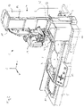
In den
Über eine Bedienoberfläche 13, welche im Bereich der Vorderseite des Grundplatte 5 angeordnet ist, ist es möglich einen Pipettiervorgang mit einer Vielzahl von Arbeitszyklen zu programmieren. Beim in den
Am Ende eines Pipettiervorganges verfährt die Stellvorrichtung 4 die Pipettiereinheit über die Abfallbox 11. Mittels eines nicht dargestellten Mechanismus werden die kontaminierten Pipettenspitzen 3 vom Verbindungsabschnitt 22 abgestreift und die abgestreiften Pipettenspitzen fallen in die Abfallbox.At the end of a pipetting process, the adjusting device 4 moves the pipetting unit over the
Dieser Vorgang wird mit einer Sensoreinheit 12 überwacht. Diese Sensoreinheit 12 befindet sich in einem mastartigen Tragarm 6 und ist dort verschwenkbar gelagert. Die Schwenkbewegung ist dabei so ausgerichtet, dass der Detektionsbereich der Sensoreinheit 12, der von einem Lichtstrahl 15 gebildet wird, in der von der X-Achse und der Y-Achse aufgespannten Ebene verschwenkt wird. Der Schwenkbereich beträgt ca.+/- 40° bezogen auf die Mittelstellung der Sensoreinheit 12. In dieser Mittelstellung der Sensoreinheit 12 ist der Detektionsbereich parallel zur X-Achse ausgerichtet. Es ist somit unmittelbar aus
Alternativ kann die Sensoreinheit 12 mit dem mastartigen Trägerelement 6 auch an der schmalen Seite der Abfallbox platziert werden. Dementsprechend wird dann auf der gegenüberliegenden schmalen Seite des Abfallbox ein Reflektorelement 16 angebracht. Allerdings macht dann ein Verschwenken der Sensoreinheit 12 kaum Sinn, weil die einzelnen Pipettenspitzen aus Sicht der Sensoreinheit sich mehr oder weniger gegenseitig überdecken und somit nicht eindeutig detektiert werden können. Vielmehr ist es hier notwendig, dass die Austrittsrichtung des Lichtstrahls 15, oder anders gesagt, dass die Hauptrichtung des Detektionsbereichs in einer Art und Weise ausgerichtet ist, dass diese Austrittrichtung einen spitzen Winkel mit der X-Achse einnimmt. Somit läuft der Lichtstrahl quer bzw. beinahe diagonal über die Öffnung der Abfallbox. Um nun die einzelnen Pipettenspitzen detektieren zu können, muss die Pipettiereinheit in X-Richtung verfahren werden. Dadurch überlappt eine Pipettenspitze 3 nach der anderen mit dem Detektionsbereich und können sequentiell detektiert werden. Diese Alternative ist in den Figuren nicht dargestellt.Alternatively, the
Eine weitere alternative, nicht dargestellte Ausführungsform kann für das mastartige Trägerelement 6 gewählt werden. Es ist nämlich denkbar, dass das Trägerelement 6 höhenverstellbar ausgeführt wird, um den Detektionsbereich der Sensoreinheit unmittelbar an die Höhe der Behälter anpassen zu können. Mögliche wäre hierzu eine teleskopartige Ausbildung des Trägerelementes vorzusehen.A further alternative embodiment, not shown, can be chosen for the mast-
Die dargestellten Ausführungsbeispiele der Erfindung wurden mit einer Pipettiereinheit 2 in der Form eines Pipettiermoduls beschrieben, welches mit dem Tragarm 14 über ein lösbares Verschlusssystem verbunden ist. Dadurch ist es möglich die Pipettiereinheit 2 aus dem Probenverteilsystem 1 herauszunehmen und als handbedienbare Pipette zu verwenden. Zur Klarstellung sei festgehalten, dass die erfindungsgemässe Idee auch bei Probenverteilsystemen eingesetzt werden kann, bei denen eine Pipettiereinheit fest mit dem Trägerarm verbunden ist bzw. bei denen die Pipettiereinheit baulich mit dem Trägerarm vereinigt ist.The illustrated exemplary embodiments of the invention were described with a pipetting unit 2 in the form of a pipetting module, which is connected to the
- 11
- Probenverteilsystemsample distribution system
- 22
- Pipettiereinheitpipetting unit
- 33
- Pipettenspitzepipette tip
- 44
- Stellvorrichtungactuator
- 55
- Grundplattebase plate
- 66
- Mastartiges TrägerelementPole-like support element
- 77
- Stellplatz für eine Vorratsbehälter für PipettenspitzenSpace for a storage container for pipette tips
- 8, 9, 108, 9, 10
- Stellplätze für Aufnahme- oder ZielbehälterPlaces for receiving or target containers
- 1111
- Abfallboxwaste box
- 1212
- Sensoreinheitsensor unit
- 1313
- Bedienoberflächeuser interface
- 1414
- Trägerarmcarrier arm
- 1515
- Lichtstrahl oder LichtpulsLight beam or light pulse
- 1616
- Reflektorelementreflector element
- 1717
- Führungsarmguide arm
- 18, 1918, 19
- Führungsschlitzeguide slots
- 2020
- Bedienelementcontrol element
- 2121
- Handgriffhandle
- 2222
- Verbindungsabschnittconnection section
- 2323
- Öffnungsrandopening edge
Claims (15)
- Sample distribution system (1)with a setting device (4) for receiving a pipetting unit (2) with at least one interchangeable pipette tip (3), wherein the setting device (4) is appropriate to change the positioning of the pipetting unit (2) with respect to a base plate (5) andwith a sensor unit (12) that is configured to detect the presence or absence or the missing of pipette tips (3),wherein the sensor unit (12) is designed as a light barrier, in particular as a reflection light barrier, and has a detection area to sense the pipette tips (3) and the sensor unit (12) and the setting device (4) are movable relative to one another in order to be suggestive to the presence of a pipette tip (3) if this pipette tip is situated in the detection area of the sensor unit (12),characterized inthat the sensor unit (12) is appropriate to scan all pipette tips (3) when pivoting the sensor unit (12).
- Sample distribution system according to claim 1,
characterized in that a counter is associated to the sensor unit (12) to determine the number of pipette tips (3). - Sample distribution system according to one of the preceding claims, characterized in that the detection area of the sensor unit (12) is formed by a single light beam or light pulse (15).
- Sample distribution system according to one of the preceding claims, characterized in that the sensor unit (12) is pivoted to swivel the detection area about the Z axis from a start position to an end position.
- Sample distribution system according to one of the preceding claims, characterized in that the sensor unit (12) is installed in such a manner that the main direction of the detection area forms an acute angle with the direction of motion parallel to the X axis of the setting device.
- Sample distribution system according to one of the preceding claims, characterized in that the sensor unit (12) is arranged in such a manner that it places the detection area over the openings of the containers.
- Sample distribution system according to one of the preceding claims, characterized in that the sensor unit (12) is connected to the base plate (5) by a mast-like support element (6) and is preferably installed in a guiding arm (17) of the setting device (4) or on a guiding arm (17) of the setting device (4).
- Sample distribution system according to one of the preceding claims, characterized in that the setting device comprises a pipetting unit (2) with at least one pipette tip (3) and the sensor unit (12) has a laser diode for emitting light pulses or light beams (15) and in particular an optic placed in front of the laser diode, wherein the light pulse or the light beam (15) has a beam diameter that is smaller than the width of the smallest pipette tip at its narrowest point and that the sensor unit (12) is appropriate to interact with a reflector element (16) and to emit the light beams or light pulses (15) in direction of this reflector element (16), wherein the reflector element (16) is preferably placed on an opening edge (23) at least of one container.
- Sample distribution system according to one of the preceding claims, characterized in that the setting device comprises a pipetting unit (2) with at least one pipette tip (3) and an evaluating unit is associated to the sensor unit (12), evaluating unit that is appropriate to evaluate the location and position of the pipette tips (3) with respect to the pipetting unit (2) as well as to the shape of the pipette tips (3).
- Method for the distribution of samples with a sample distribution system according to one of the preceding claims that comprises the following steps:a) Reception of pipette tips (3) by means of a pipetting unit (2),b) Performing of at least one pipetting operation,c) Displacement of the pipetting unit (2) to a detection area of the sensor unit (12),d) Moving of the pipetting unit (2) with respect to the sensor unit (12) in order to check in a checking step by scanning with a light beam or light pulse if a pipette tip (3) is in the detection area of the sensor unit (12), wherein the checking step is performed by means of the sensor unit (12) that is designed as a light barrier, the sensor unit (12) emits during the checking step light beams or light pulses in direction of a reflector element (16) and that the light beams or light pulses are reflected, in case that no pipette tip (3) is in the light path of the light beam or of the light pulse (15), on the reflector element and are reflected back to the sensor unit (12).
- Method for the distribution of samples according to claim 10, characterized in thata) it is checked in a first checking step if all the received pipette tips (3) are connected with the pipetting unit (2),b) and it is checked in a second checking step if all the pipette tips (3) are thrown off.
- Method for the distribution of samples according to claim 11, characterized in that the following method steps are performed during the first and the second checking step:a) setting of a counter at zero,b) activating of the sensor unit (12) and emitting of a light beam or light pulse (15), wherein the main direction of the detection area forms an acute angle with the direction of motion along the X axis of the pipetting unit (2),c) displacement of the pipetting unit (2) until a pipette tip (3) is detected by overlapping with the detection area and the interruption of the light beam or light pulse (15) connected herewith,d) increasing of the number of detected pipette tips by one,e) repeating of the steps starting with b).
- Method for the distribution of samples according to claim 11, characterized in that the following method steps are performed during the first and the second checking step:a) setting of a counter at zero and pivoting of a sensor unit (12) into a starting position,b) activating of the sensor unit (12) and emitting of a light beam or light pulse (15),c) pivoting of the light beam or light pulse (15) until a pipette tip (3) is detected by overlapping with the detection area and the interruption of the light beam or light pulse (15) connected herewith,d) increasing of the number of detected pipette tips by one,e) repeating of the steps starting with b) until an end position has been reached.
- Method for the distribution of samples according to one of the claims 12 or 13, characterized in that the method steps b) and c) are performed in order to determine a signal sequence of light and dark spots and that the signal sequence is evaluated to detect the number of pipette tips from the number of dark spots.
- Method for the distribution of samples according to one of the claims 11, 12, 13 or 14,
characterized in that that the following method steps are performed during the first or the second checking step:a) reading out of the number of detected pipette tips from the counter,b) comparing of the number of detected pipette tips with the number of inserted pipette tips (3),c) starting of a new pipette cycle if the counter reading coincides with the number of pipette tips,d) output of an error message if the counter reading does not coincide with the number of pipette tips.
Applications Claiming Priority (1)
| Application Number | Priority Date | Filing Date | Title |
|---|---|---|---|
| CH01583/17A CH714486A1 (en) | 2017-12-21 | 2017-12-21 | Sample distribution system and method for distributing samples. |
Publications (2)
| Publication Number | Publication Date |
|---|---|
| EP3501655A1 EP3501655A1 (en) | 2019-06-26 |
| EP3501655B1 true EP3501655B1 (en) | 2022-05-18 |
Family
ID=62683071
Family Applications (1)
| Application Number | Title | Priority Date | Filing Date |
|---|---|---|---|
| EP18215662.0A Active EP3501655B1 (en) | 2017-12-21 | 2018-12-21 | Sample distribution system and method for distributing samples |
Country Status (3)
| Country | Link |
|---|---|
| US (1) | US11073530B2 (en) |
| EP (1) | EP3501655B1 (en) |
| CH (1) | CH714486A1 (en) |
Families Citing this family (4)
| Publication number | Priority date | Publication date | Assignee | Title |
|---|---|---|---|---|
| CA3091530A1 (en) * | 2018-02-27 | 2019-09-06 | Eppendorf Ag | Measuring apparatus for a laboratory appliance for measuring an article, article for said measuring apparatus and measuring method |
| CN111167532A (en) * | 2020-01-10 | 2020-05-19 | 济南翼菲自动化科技有限公司 | Automatic device for biological test liquid transfer |
| DE102021204570A1 (en) | 2021-05-06 | 2022-11-10 | Fraunhofer-Gesellschaft zur Förderung der angewandten Forschung eingetragener Verein | Dosing head and fluidic system for receiving and dosing at least one medium |
| CN114460320B (en) * | 2022-04-14 | 2022-06-21 | 深圳市帝迈生物技术有限公司 | Sample analyzer and sample detection process thereof |
Family Cites Families (33)
| Publication number | Priority date | Publication date | Assignee | Title |
|---|---|---|---|---|
| US3588480A (en) | 1968-12-06 | 1971-06-28 | Fairbanks Morse Inc | Processing control system |
| US4478094A (en) * | 1983-01-21 | 1984-10-23 | Cetus Corporation | Liquid sample handling system |
| US4616514A (en) | 1983-06-06 | 1986-10-14 | Rainin Instrument Co., Inc. | Replaceable tip assembly for pipette |
| GB2147996A (en) | 1983-10-12 | 1985-05-22 | Sundberg Carl Axel | Electrical measurement of the dimensions or volumes of articles |
| FI87740C (en) | 1990-05-04 | 1994-04-08 | Biohit Oy | pipette |
| US5141871A (en) * | 1990-05-10 | 1992-08-25 | Pb Diagnostic Systems, Inc. | Fluid dispensing system with optical locator |
| US5290521A (en) | 1992-09-04 | 1994-03-01 | Destefano Jr Albert M | Lab-top work station |
| US6090348A (en) | 1997-03-14 | 2000-07-18 | Becton, Dickinson And Company | Method for programming an electronic pipetter |
| DE19850841A1 (en) | 1998-11-04 | 2000-05-25 | Eppendorf Geraetebau Netheler | Method for operating an electronic dosing system and dosing system for carrying out the method |
| DE10040849A1 (en) * | 2000-08-21 | 2002-03-21 | Mwg Biotech Ag | Pipetting head for a robot with several pipetting tips |
| US7288228B2 (en) | 2002-02-12 | 2007-10-30 | Gilson, Inc. | Sample injection system |
| US7976793B2 (en) | 2003-11-27 | 2011-07-12 | Gilson S.A.S. | Electronic pipette |
| DE102004003434B4 (en) | 2004-01-21 | 2006-06-08 | Eppendorf Ag | Pipetting device with a displacement device and a drive device detachably connected thereto |
| US7618589B2 (en) * | 2004-09-07 | 2009-11-17 | Hitachi Koki Co., Ltd. | Automatic dispenser |
| JP5271908B2 (en) | 2006-09-01 | 2013-08-21 | エイジーアール インターナショナル,インコーポレイテッド | Inspection system, blow molding system, method of inspecting plastic containers, and method of manufacturing plastic containers |
| US7662344B2 (en) | 2006-10-24 | 2010-02-16 | Viaflo Corporation | Locking pipette tip and mounting shaft |
| DE102008010267A1 (en) | 2008-02-19 | 2009-08-20 | Nyársik, Lajos, Dr. | Pipette device for manually applying fluid on platform in biochemical laboratory, has marking position indicated at marking element, and coupling unit with pin for fixing pipette unit position in slider at marking unit in marking position |
| US8029742B2 (en) | 2008-05-05 | 2011-10-04 | Integra Biosciences Corp. | Multi-channel pipettor with repositionable tips |
| US8743368B2 (en) * | 2009-11-12 | 2014-06-03 | General Electric Company | Optical sensor system and method of sensing |
| JP2011115759A (en) | 2009-12-07 | 2011-06-16 | Fukae Kasei Kk | Pipette device |
| DE102010005722A1 (en) | 2010-01-26 | 2011-07-28 | Eppendorf AG, 22339 | Positioning device for a sample distribution device, sample distribution device with positioning device and method for positioning |
| WO2011140071A1 (en) | 2010-05-03 | 2011-11-10 | Integra Biosciences Corp. (Formerly Viaflo Corporation) | Pipette tip positioning for manually-directed, multi-channel electronic pipettor |
| JP5419194B2 (en) | 2010-05-03 | 2014-02-19 | インテグラ バイオサイエンシズ コープ. | Manually oriented multi-channel electronic pipette system |
| EP2643701B1 (en) | 2010-11-23 | 2020-07-08 | Andrew Alliance S.A | Devices and methods for programmable manipulation of pipettes |
| JP6117217B2 (en) * | 2011-09-30 | 2017-04-19 | ベクトン・ディキンソン・アンド・カンパニーBecton, Dickinson And Company | Unitized reagent strip |
| EP2698202A3 (en) | 2012-08-15 | 2017-07-19 | Integra Biosciences AG | Sample distribution system and process |
| PL2735369T3 (en) | 2012-11-23 | 2017-09-29 | Eppendorf Ag | Multichannel pipette |
| US9815053B2 (en) | 2013-01-15 | 2017-11-14 | Mettler-Toledo Rainin, LLC | Liquid end assembly for a multichannel air displacement pipette |
| US9555407B2 (en) * | 2013-03-14 | 2017-01-31 | Protedyne Corporation | Laser triangulation for pipette tip position |
| EP2884285A1 (en) * | 2013-12-13 | 2015-06-17 | F. Hoffmann-La Roche AG | Supply module for an automated analyzer |
| WO2016166622A1 (en) | 2015-04-16 | 2016-10-20 | Integra Biosciences Ag | Volume adjustment for manual pipettor |
| WO2017116960A2 (en) * | 2015-12-30 | 2017-07-06 | Theranos, Inc. | Multi-piece fluid transfer tip |
| CH712010B1 (en) | 2016-01-11 | 2021-10-15 | Integra Biosciences Ag | Pipette with ejection mechanism for pipette tips. |
-
2017
- 2017-12-21 CH CH01583/17A patent/CH714486A1/en unknown
-
2018
- 2018-12-19 US US16/225,232 patent/US11073530B2/en active Active
- 2018-12-21 EP EP18215662.0A patent/EP3501655B1/en active Active
Also Published As
| Publication number | Publication date |
|---|---|
| US20190195906A1 (en) | 2019-06-27 |
| EP3501655A1 (en) | 2019-06-26 |
| US11073530B2 (en) | 2021-07-27 |
| CH714486A1 (en) | 2019-06-28 |
Similar Documents
| Publication | Publication Date | Title |
|---|---|---|
| EP3501655B1 (en) | Sample distribution system and method for distributing samples | |
| DE69835691T2 (en) | Multiple channel pipetting | |
| EP1726923B1 (en) | Filling level measurement method and device | |
| EP3554708B1 (en) | Method for detecting the type of an exchangeable piston-cylinder unit for a dispenser | |
| EP2027926A1 (en) | Apparatus for processing biological material | |
| EP0691158A2 (en) | Pipetting system | |
| EP0301390A2 (en) | Feeler head for coordinate measuring machines | |
| EP1489425B1 (en) | Device and method for positioning functional elements and/or vessels on the work space of a laboratory manipulator by the help of two crossing light barriers | |
| EP3554707B1 (en) | Fitting a piston/cylinder unit on, and releasing one such from, a dispenser for receiving and dispensing volumes of fluid | |
| EP3403725A1 (en) | Pipetting assistance system | |
| EP2350676B1 (en) | Automated analytical device comprising an automatic pipetting device and a pipetting arm having a crash sensor | |
| DE4405661C2 (en) | Method and device for mechanical joining of non-metallic workpieces | |
| EP2620775A1 (en) | Holder cartridge | |
| DE19915771C1 (en) | Pipette system for receiving and releasing fluid volumes has an information reader fixed in the syringe holder on the injection ram receiver so that the reader follows the lifting movements of the ram | |
| DE19914962A1 (en) | Optoelectronic device | |
| WO2020234325A1 (en) | Liquid screening assembly with mechanical release of very small liquid quantities | |
| EP3489693B1 (en) | Method for controlling a pipette device | |
| EP3908842A1 (en) | Pipetting device and method for the transfer of fluids | |
| WO2017001676A1 (en) | Pipetting apparatus with image processing | |
| EP1745861A1 (en) | Apparatus for gauging and sorting | |
| DE102018131088A1 (en) | Liquid dosing device for ballistic delivery of dosing quantities in the nanoliter range, liquid dosing method and pipette tip for this | |
| DE102020211533B3 (en) | Measuring instrument for a laser tool, laser tool and workpiece processing device, and method for measuring a distance | |
| DE19751377A1 (en) | Hardness testing apparatus for elastomers | |
| DE3342504A1 (en) | Pipetting device | |
| DE4324109A1 (en) | Thread testing device |
Legal Events
| Date | Code | Title | Description |
|---|---|---|---|
| PUAI | Public reference made under article 153(3) epc to a published international application that has entered the european phase |
Free format text: ORIGINAL CODE: 0009012 |
|
| STAA | Information on the status of an ep patent application or granted ep patent |
Free format text: STATUS: THE APPLICATION HAS BEEN PUBLISHED |
|
| AK | Designated contracting states |
Kind code of ref document: A1 Designated state(s): AL AT BE BG CH CY CZ DE DK EE ES FI FR GB GR HR HU IE IS IT LI LT LU LV MC MK MT NL NO PL PT RO RS SE SI SK SM TR |
|
| AX | Request for extension of the european patent |
Extension state: BA ME |
|
| STAA | Information on the status of an ep patent application or granted ep patent |
Free format text: STATUS: REQUEST FOR EXAMINATION WAS MADE |
|
| 17P | Request for examination filed |
Effective date: 20191213 |
|
| RBV | Designated contracting states (corrected) |
Designated state(s): AL AT BE BG CH CY CZ DE DK EE ES FI FR GB GR HR HU IE IS IT LI LT LU LV MC MK MT NL NO PL PT RO RS SE SI SK SM TR |
|
| STAA | Information on the status of an ep patent application or granted ep patent |
Free format text: STATUS: EXAMINATION IS IN PROGRESS |
|
| 17Q | First examination report despatched |
Effective date: 20210224 |
|
| GRAP | Despatch of communication of intention to grant a patent |
Free format text: ORIGINAL CODE: EPIDOSNIGR1 |
|
| STAA | Information on the status of an ep patent application or granted ep patent |
Free format text: STATUS: GRANT OF PATENT IS INTENDED |
|
| INTG | Intention to grant announced |
Effective date: 20210714 |
|
| GRAJ | Information related to disapproval of communication of intention to grant by the applicant or resumption of examination proceedings by the epo deleted |
Free format text: ORIGINAL CODE: EPIDOSDIGR1 |
|
| STAA | Information on the status of an ep patent application or granted ep patent |
Free format text: STATUS: EXAMINATION IS IN PROGRESS |
|
| INTC | Intention to grant announced (deleted) | ||
| GRAP | Despatch of communication of intention to grant a patent |
Free format text: ORIGINAL CODE: EPIDOSNIGR1 |
|
| STAA | Information on the status of an ep patent application or granted ep patent |
Free format text: STATUS: GRANT OF PATENT IS INTENDED |
|
| INTG | Intention to grant announced |
Effective date: 20211208 |
|
| GRAS | Grant fee paid |
Free format text: ORIGINAL CODE: EPIDOSNIGR3 |
|
| GRAA | (expected) grant |
Free format text: ORIGINAL CODE: 0009210 |
|
| STAA | Information on the status of an ep patent application or granted ep patent |
Free format text: STATUS: THE PATENT HAS BEEN GRANTED |
|
| AK | Designated contracting states |
Kind code of ref document: B1 Designated state(s): AL AT BE BG CH CY CZ DE DK EE ES FI FR GB GR HR HU IE IS IT LI LT LU LV MC MK MT NL NO PL PT RO RS SE SI SK SM TR |
|
| REG | Reference to a national code |
Ref country code: GB Ref legal event code: FG4D Free format text: NOT ENGLISH |
|
| REG | Reference to a national code |
Ref country code: CH Ref legal event code: EP |
|
| REG | Reference to a national code |
Ref country code: IE Ref legal event code: FG4D Free format text: LANGUAGE OF EP DOCUMENT: GERMAN |
|
| REG | Reference to a national code |
Ref country code: AT Ref legal event code: REF Ref document number: 1492842 Country of ref document: AT Kind code of ref document: T Effective date: 20220615 Ref country code: DE Ref legal event code: R096 Ref document number: 502018009702 Country of ref document: DE |
|
| REG | Reference to a national code |
Ref country code: LT Ref legal event code: MG9D |
|
| REG | Reference to a national code |
Ref country code: NL Ref legal event code: MP Effective date: 20220518 |
|
| PG25 | Lapsed in a contracting state [announced via postgrant information from national office to epo] |
Ref country code: SE Free format text: LAPSE BECAUSE OF FAILURE TO SUBMIT A TRANSLATION OF THE DESCRIPTION OR TO PAY THE FEE WITHIN THE PRESCRIBED TIME-LIMIT Effective date: 20220518 Ref country code: PT Free format text: LAPSE BECAUSE OF FAILURE TO SUBMIT A TRANSLATION OF THE DESCRIPTION OR TO PAY THE FEE WITHIN THE PRESCRIBED TIME-LIMIT Effective date: 20220919 Ref country code: NO Free format text: LAPSE BECAUSE OF FAILURE TO SUBMIT A TRANSLATION OF THE DESCRIPTION OR TO PAY THE FEE WITHIN THE PRESCRIBED TIME-LIMIT Effective date: 20220818 Ref country code: NL Free format text: LAPSE BECAUSE OF FAILURE TO SUBMIT A TRANSLATION OF THE DESCRIPTION OR TO PAY THE FEE WITHIN THE PRESCRIBED TIME-LIMIT Effective date: 20220518 Ref country code: LT Free format text: LAPSE BECAUSE OF FAILURE TO SUBMIT A TRANSLATION OF THE DESCRIPTION OR TO PAY THE FEE WITHIN THE PRESCRIBED TIME-LIMIT Effective date: 20220518 Ref country code: HR Free format text: LAPSE BECAUSE OF FAILURE TO SUBMIT A TRANSLATION OF THE DESCRIPTION OR TO PAY THE FEE WITHIN THE PRESCRIBED TIME-LIMIT Effective date: 20220518 Ref country code: GR Free format text: LAPSE BECAUSE OF FAILURE TO SUBMIT A TRANSLATION OF THE DESCRIPTION OR TO PAY THE FEE WITHIN THE PRESCRIBED TIME-LIMIT Effective date: 20220819 Ref country code: FI Free format text: LAPSE BECAUSE OF FAILURE TO SUBMIT A TRANSLATION OF THE DESCRIPTION OR TO PAY THE FEE WITHIN THE PRESCRIBED TIME-LIMIT Effective date: 20220518 Ref country code: ES Free format text: LAPSE BECAUSE OF FAILURE TO SUBMIT A TRANSLATION OF THE DESCRIPTION OR TO PAY THE FEE WITHIN THE PRESCRIBED TIME-LIMIT Effective date: 20220518 Ref country code: BG Free format text: LAPSE BECAUSE OF FAILURE TO SUBMIT A TRANSLATION OF THE DESCRIPTION OR TO PAY THE FEE WITHIN THE PRESCRIBED TIME-LIMIT Effective date: 20220818 |
|
| PG25 | Lapsed in a contracting state [announced via postgrant information from national office to epo] |
Ref country code: RS Free format text: LAPSE BECAUSE OF FAILURE TO SUBMIT A TRANSLATION OF THE DESCRIPTION OR TO PAY THE FEE WITHIN THE PRESCRIBED TIME-LIMIT Effective date: 20220518 Ref country code: PL Free format text: LAPSE BECAUSE OF FAILURE TO SUBMIT A TRANSLATION OF THE DESCRIPTION OR TO PAY THE FEE WITHIN THE PRESCRIBED TIME-LIMIT Effective date: 20220518 Ref country code: LV Free format text: LAPSE BECAUSE OF FAILURE TO SUBMIT A TRANSLATION OF THE DESCRIPTION OR TO PAY THE FEE WITHIN THE PRESCRIBED TIME-LIMIT Effective date: 20220518 Ref country code: IS Free format text: LAPSE BECAUSE OF FAILURE TO SUBMIT A TRANSLATION OF THE DESCRIPTION OR TO PAY THE FEE WITHIN THE PRESCRIBED TIME-LIMIT Effective date: 20220918 |
|
| PG25 | Lapsed in a contracting state [announced via postgrant information from national office to epo] |
Ref country code: SM Free format text: LAPSE BECAUSE OF FAILURE TO SUBMIT A TRANSLATION OF THE DESCRIPTION OR TO PAY THE FEE WITHIN THE PRESCRIBED TIME-LIMIT Effective date: 20220518 Ref country code: SK Free format text: LAPSE BECAUSE OF FAILURE TO SUBMIT A TRANSLATION OF THE DESCRIPTION OR TO PAY THE FEE WITHIN THE PRESCRIBED TIME-LIMIT Effective date: 20220518 Ref country code: RO Free format text: LAPSE BECAUSE OF FAILURE TO SUBMIT A TRANSLATION OF THE DESCRIPTION OR TO PAY THE FEE WITHIN THE PRESCRIBED TIME-LIMIT Effective date: 20220518 Ref country code: EE Free format text: LAPSE BECAUSE OF FAILURE TO SUBMIT A TRANSLATION OF THE DESCRIPTION OR TO PAY THE FEE WITHIN THE PRESCRIBED TIME-LIMIT Effective date: 20220518 Ref country code: DK Free format text: LAPSE BECAUSE OF FAILURE TO SUBMIT A TRANSLATION OF THE DESCRIPTION OR TO PAY THE FEE WITHIN THE PRESCRIBED TIME-LIMIT Effective date: 20220518 Ref country code: CZ Free format text: LAPSE BECAUSE OF FAILURE TO SUBMIT A TRANSLATION OF THE DESCRIPTION OR TO PAY THE FEE WITHIN THE PRESCRIBED TIME-LIMIT Effective date: 20220518 |
|
| REG | Reference to a national code |
Ref country code: DE Ref legal event code: R097 Ref document number: 502018009702 Country of ref document: DE |
|
| PLBE | No opposition filed within time limit |
Free format text: ORIGINAL CODE: 0009261 |
|
| STAA | Information on the status of an ep patent application or granted ep patent |
Free format text: STATUS: NO OPPOSITION FILED WITHIN TIME LIMIT |
|
| PG25 | Lapsed in a contracting state [announced via postgrant information from national office to epo] |
Ref country code: AL Free format text: LAPSE BECAUSE OF FAILURE TO SUBMIT A TRANSLATION OF THE DESCRIPTION OR TO PAY THE FEE WITHIN THE PRESCRIBED TIME-LIMIT Effective date: 20220518 |
|
| 26N | No opposition filed |
Effective date: 20230221 |
|
| PGFP | Annual fee paid to national office [announced via postgrant information from national office to epo] |
Ref country code: CH Payment date: 20230104 Year of fee payment: 5 |
|
| PG25 | Lapsed in a contracting state [announced via postgrant information from national office to epo] |
Ref country code: SI Free format text: LAPSE BECAUSE OF FAILURE TO SUBMIT A TRANSLATION OF THE DESCRIPTION OR TO PAY THE FEE WITHIN THE PRESCRIBED TIME-LIMIT Effective date: 20220518 |
|
| REG | Reference to a national code |
Ref country code: BE Ref legal event code: MM Effective date: 20221231 |
|
| PG25 | Lapsed in a contracting state [announced via postgrant information from national office to epo] |
Ref country code: LU Free format text: LAPSE BECAUSE OF NON-PAYMENT OF DUE FEES Effective date: 20221221 |
|
| PG25 | Lapsed in a contracting state [announced via postgrant information from national office to epo] |
Ref country code: IE Free format text: LAPSE BECAUSE OF NON-PAYMENT OF DUE FEES Effective date: 20221221 |
|
| PG25 | Lapsed in a contracting state [announced via postgrant information from national office to epo] |
Ref country code: FR Free format text: LAPSE BECAUSE OF NON-PAYMENT OF DUE FEES Effective date: 20221231 Ref country code: BE Free format text: LAPSE BECAUSE OF NON-PAYMENT OF DUE FEES Effective date: 20221231 |
|
| PGFP | Annual fee paid to national office [announced via postgrant information from national office to epo] |
Ref country code: GB Payment date: 20231220 Year of fee payment: 6 |
|
| PG25 | Lapsed in a contracting state [announced via postgrant information from national office to epo] |
Ref country code: IT Free format text: LAPSE BECAUSE OF FAILURE TO SUBMIT A TRANSLATION OF THE DESCRIPTION OR TO PAY THE FEE WITHIN THE PRESCRIBED TIME-LIMIT Effective date: 20220518 |
|
| PGFP | Annual fee paid to national office [announced via postgrant information from national office to epo] |
Ref country code: DE Payment date: 20231214 Year of fee payment: 6 |
|
| REG | Reference to a national code |
Ref country code: CH Ref legal event code: PK Free format text: BERICHTIGUNGEN |
|
| PG25 | Lapsed in a contracting state [announced via postgrant information from national office to epo] |
Ref country code: HU Free format text: LAPSE BECAUSE OF FAILURE TO SUBMIT A TRANSLATION OF THE DESCRIPTION OR TO PAY THE FEE WITHIN THE PRESCRIBED TIME-LIMIT; INVALID AB INITIO Effective date: 20181221 |
|
| PG25 | Lapsed in a contracting state [announced via postgrant information from national office to epo] |
Ref country code: CY Free format text: LAPSE BECAUSE OF FAILURE TO SUBMIT A TRANSLATION OF THE DESCRIPTION OR TO PAY THE FEE WITHIN THE PRESCRIBED TIME-LIMIT Effective date: 20220511 |
|
| PGFP | Annual fee paid to national office [announced via postgrant information from national office to epo] |
Ref country code: CH Payment date: 20240101 Year of fee payment: 6 |