EP1489381A2 - Procédé et dispositif de compensation d'erreurs d'accélération et système de navigation intertiel utilisant ce procédé - Google Patents
Procédé et dispositif de compensation d'erreurs d'accélération et système de navigation intertiel utilisant ce procédé Download PDFInfo
- Publication number
- EP1489381A2 EP1489381A2 EP04014129A EP04014129A EP1489381A2 EP 1489381 A2 EP1489381 A2 EP 1489381A2 EP 04014129 A EP04014129 A EP 04014129A EP 04014129 A EP04014129 A EP 04014129A EP 1489381 A2 EP1489381 A2 EP 1489381A2
- Authority
- EP
- European Patent Office
- Prior art keywords
- acceleration
- time interval
- error
- stationary
- moving
- Prior art date
- Legal status (The legal status is an assumption and is not a legal conclusion. Google has not performed a legal analysis and makes no representation as to the accuracy of the status listed.)
- Granted
Links
Images


Classifications
-
- G—PHYSICS
- G08—SIGNALLING
- G08G—TRAFFIC CONTROL SYSTEMS
- G08G5/00—Traffic control systems for aircraft, e.g. air-traffic control [ATC]
-
- G—PHYSICS
- G01—MEASURING; TESTING
- G01C—MEASURING DISTANCES, LEVELS OR BEARINGS; SURVEYING; NAVIGATION; GYROSCOPIC INSTRUMENTS; PHOTOGRAMMETRY OR VIDEOGRAMMETRY
- G01C21/00—Navigation; Navigational instruments not provided for in groups G01C1/00 - G01C19/00
- G01C21/10—Navigation; Navigational instruments not provided for in groups G01C1/00 - G01C19/00 by using measurements of speed or acceleration
- G01C21/12—Navigation; Navigational instruments not provided for in groups G01C1/00 - G01C19/00 by using measurements of speed or acceleration executed aboard the object being navigated; Dead reckoning
- G01C21/16—Navigation; Navigational instruments not provided for in groups G01C1/00 - G01C19/00 by using measurements of speed or acceleration executed aboard the object being navigated; Dead reckoning by integrating acceleration or speed, i.e. inertial navigation
- G01C21/183—Compensation of inertial measurements, e.g. for temperature effects
- G01C21/188—Compensation of inertial measurements, e.g. for temperature effects for accumulated errors, e.g. by coupling inertial systems with absolute positioning systems
-
- G—PHYSICS
- G01—MEASURING; TESTING
- G01C—MEASURING DISTANCES, LEVELS OR BEARINGS; SURVEYING; NAVIGATION; GYROSCOPIC INSTRUMENTS; PHOTOGRAMMETRY OR VIDEOGRAMMETRY
- G01C25/00—Manufacturing, calibrating, cleaning, or repairing instruments or devices referred to in the other groups of this subclass
Definitions
- the present invention relates to a method and apparatus for correcting acceleration errors, and more particularly, to a method and apparatus for compensating for an error in position determined by an inertial navigation system (INS), an INS therefor, and a method, which calculates a position in the INS.
- INS inertial navigation system
- INS inertial navigation system
- inertial sensors including tri-axial acceleration sensors and tri-axial gyroscopes are used to measure the position and orientation of a moving object of interest in a three-dimensional space.
- INS orientation is obtained by solving differential equations to integrate angular velocities measured by the gyroscopes
- position is obtained by removing gravity components from accelerations measured by the acceleration sensors, taking into account the INS orientation, and then calculating double integrals of the accelerations with respect to time.
- INS orientation error derived from error in the gyroscope measurement increases with time, errors in the accelerations from which the gravity components has been removed also increase with time.
- ZUPTs zero velocity updates
- CUPTs coordinate updates
- orientation updates are widely used to correct sensor errors.
- the ZUPTs are processes to reset a velocity of the INS to zero if the INS is detected to be stationary.
- the CUPTs are performed to reset an origin, when the INS reaches a predetermined position, to the predetermined position.
- the orientation is reset an orientation at the origin, when the INS takes a predetermined orientation, to the predetermined orientation.
- U.S. Patent No. 6,292,751 discloses a method for correcting acceleration errors caused while an INS is in motion. This method assumes acceleration errors are constant. An acceleration error is calculated, under a condition that a velocity is zero at the time when the INS starts to move and stops. Then, the error is subtracted from the measured acceleration and the resulting value is doubly integrated with respect to time in order to determine the position.
- FIG. 2 shows a process of compensating for velocity errors through acceleration error correction.
- FIG. 2A shows a measured acceleration A of the INS and an acceleration error d indicated by a dotted line.
- FIG. 2B a velocity, which is obtained by integrating the acceleration A, is appeared as a first-order function. Since a velocity of the INS is 0 at time t1 before starting to move, the velocity of the INS at time t1 can be corrected to 0-as shown in FIG. 2C.
- INS inertial navigation system
- an apparatus for compensating for an acceleration error including: a first acceleration error calculator that approximates acceleration information for a stationary time interval when a system is stationary by first-order functions in order to calculate acceleration errors for the stationary time interval; a zero velocity compensator that compensates system velocities for the stationary time intervals and accelerations derived from the velocities; and a second acceleration error calculator that calculates an acceleration error for a moving time interval when the system is moving using the approximated acceleration errors for the stationary time intervals and outputs an acceleration subjected to error correction for the moving time interval using the acceleration error and measured acceleration for the moving time interval and the corrected accelerations for-the stationary time intervals.
- the second acceleration error calculator may determine a slope of the acceleration error for the moving time interval using slopes of a first first-order function approximating an acceleration error for a stationary time interval before the moving time interval, and a second first-order function approximating an acceleration error for a stationary time interval after the moving time interval. That is, the second acceleration error calculator may determine the slope of the acceleration error for the moving time interval using a first first-order function value produced at the moment when the system undergoes a transition from a stationary state to a moving state and a second first order function value- produced at the moment when the system undergoes a transition from a moving state to a stationary state.
- an INS including: a motion detector that detects the motion of the INS and outputs information on stationary time intervals during which the INS is stationary and a moving time interval during which the INS is moving; a sensor portion that measures accelerations of the INS for the stationary time intervals and moving time interval, respectively; an error model determiner that determines an acceleration error corresponding to the moving time interval using accelerations measured during the stationary time intervals and outputs an acceleration subjected to correction of the acceleration error for the moving time interval; and a position calculator that integrates the corrected acceleration for the moving time interval and outputs the position of the INS.
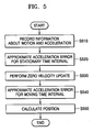
- a method for compensating for an acceleration error including: approximating acceleration errors for the stationary time intervals by each first-order function using acceleration information about the stationary time intervals; performing zero velocity updates to correct the accelerations for the stationary time intervals; approximating an acceleration error for the moving time interval by a first-order function using the acceleration errors approximated for the stationary time intervals; and subtracting the acceleration error for the moving time interval from the acceleration information and calculating acceleration subjected to error correction for the moving time interval.
- a slope of the acceleration error for the moving time interval is determined using slopes of a first first-order function approximating an acceleration error for a stationary time interval before the moving time interval, and a second first-order function approximating an acceleration error for a stationary time interval after the moving time interval.
- the slope of the acceleration error for the moving time interval is determined using a first first-order function value produced at the moment when the system undergoes a transition from a stationary state to a moving state and a second first-order function value produced at the moment when the system undergoes a transition from a moving state to a stationary state.
- a method for calculating the position of an INS including: recording acceleration information of the INS and information about stationary time intervals when the INS is stationary and a moving time interval when the INS is moving, determined according to the acceleration information; approximating acceleration errors for the stationary time intervals by each first-order function using the acceleration information for the stationary time intervals, and performing zero velocity updates to correct the accelerations for the stationary time intervals; approximating an acceleration error for the moving time interval by a first-order function using the acceleration errors for the stationary time intervals, and calculating an acceleration subjected to error correction for the moving time interval; and calculating the position of the INS using the corrected accelerations for the stationary and moving time intervals.
- an inertial navigation system includes a sensor portion 310 comprising acceleration sensors and gyroscopes that measure 3 axis acceleration and 3 axis angular velocity, respectively, along three axes, a motion detector 320 that determines whether the INS including the sensor portion 310 is stationary, an acceleration error model determiner 330 that determines a linear model for an acceleration sensor error, and a position calculator 340 that calculates an actual position of the INS from an acceleration compensated using the linear model.
- the motion detector 320 if in direct control of the motion of the INS, simply outputs the time when the INS including the sensor portion 310 is moving or stationary.
- the motion detector 320 determines that the INS is stationary if a value measured by the sensor portion 310 is less than a predetermined threshold and determines that the INS is moving if the measured value is greater than the threshold.
- the acceleration error model determiner 330 includes first and second information recorders 331 and 333, a zero velocity compensator 337, and first and second acceleration error calculators 335 and 339.
- the first information recorder 331 records acceleration information while the INS is stationary, i.e., before it starts moving or after it stops moving.
- the first acceleration error calculator 335 approximates the acceleration for a time interval when the INS is stationary ("stationary time interval") by a linear function and calculates an error in the acceleration for the stationary time interval.
- the zero velocity compensator 337 corrects for the INS velocity and acceleration for the stationary time interval.
- the second information recorder 333 records acceleration information measured while the INS is moving.
- the second acceleration error calculator 339 calculates an acceleration for a time interval when the INS is moving ("moving time interval") corrected by using the approximated acceleration error and the corrected zero velocity corresponding to the stationary time interval.
- the position calculator 340 performs a double integral of the corrected acceleration calculated by the acceleration error model determiner 330 and calculates an INS position.
- FIG. 4 shows acceleration in an absolute coordinate system measured by the sensor 310.
- the theoretical background of the present invention will now be described with reference to FIG. 4.
- the present invention is proposed to overcome the limit posed by conventional technology where an acceleration error is modeled as a constant; the present invention proposes additional conditions for modeling an acceleration error derived while the INS is moving as a first-order equation.
- the acceleration error is not constant during a stationary time interval, but increases or decreases linearly as shown in FIG. 4, the way in which an acceleration error changes during a moving time interval cannot be known.
- n+1 coefficients must be determined, which requires n+1 conditional expressions. Since the only intuitively known condition is that the velocity is 0 when the INS is stationary, the present invention provides additional conditions that allow an acceleration sensor measurement error in an absolute coordinate system to be modeled as a first-order expression in the form at+b.
- FIG. 5 is a flowchart illustrating a method for compensating for an acceleration error according to a preferred embodiment of the present invention
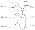
- FIG. 6 shows accelerations measured and corrected in each step of the method illustrated in FIG. 5.
- step S510 when an INS starts to operate, accelerations along three axes sensed by the acceleration sensors contained in the sensor portion 310, and motion information detected by the motion detector 320, are input to the first and second information recorders 331 and 333.
- the first information recorder 331 records the input accelerations along three axes corresponding to a time interval when the motion detector 320 senses that the INS is stationary, and outputs the recorded acceleration information to the first acceleration error calculator 335 and the zero velocity compensator 337.
- the second information recorder 333 records the input accelerations along three axes for a time interval t between t1 and t2 when the motion detector 320 senses that the INS is moving, and outputs the recorded accelerations to the second acceleration error calculator 339.
- step S520 the first acceleration error calculator 335 performs a linear regression on the accelerations recorded for a time interval between 0 and t1 before the INS starts to move to obtain a straight line a 1 t+b 1 , linearly approximated as shown in FIG. 6A.
- the first acceleration error calculator 335 performs a linear regression on the accelerations recorded for a time interval after t2 when the INS stops moving to obtain a straight line a 2 t+b 2 , linearly approximated as shown in FIG. 6A.
- the approximated straight lines are output to the second acceleration error calculator 339.
- step S530 the zero velocity compensator 337 performs a zero velocity update (ZUPT) on velocities for stationary time intervals received from the first information recorder 331. That is, as described above, it can be known intuitively that the INS has 0 velocity during the stationary time intervals between 0 and t1 and after t2, and thus has 0 accelerations during the same intervals. Thus, the zero velocity compensator 337 corrects the accelerations during the stationary time intervals to 0 as shown in FIG. 6A and then outputs the corrected acceleration information to the second error acceleration calculator 339.
- ZUPT zero velocity update
- step S540 the second error acceleration calculator 339 approximates an acceleration error at+b in the moving time interval using the approximated acceleration errors a 1 t+b 1 and a 2 t+b 2 . Then, the second error acceleration calculator 339 determines slope a and constant b of the approximated acceleration error for the moving time interval.
- Equation (4) can be rearranged to isolate constant b as shown in Equation (5):
- Equation (3) The acceleration error at+b for the moving time interval between t1 and t2 obtained by Equations (3) and (5) is shown in FIG. 6B along with the curve of an acceleration A', subjected to a ZUPT.
- FIG. 6C shows the acceleration curve subjected to ZUPT and the error correction for the moving time interval.
- the position calculator 340 performs a double integral on the corrected acceleration A" received from the second acceleration error calculator 339 and calculates a position P of the INS.
- FIGS. 7A and 7B show a performance comparison between a handwriting recovery device using a conventional INS and a handwriting recovery device using an INS performing an acceleration error compensation method according to the present invention.
- an upper picture of FIG. 7A shows a position locus calculated by conventional technology and a lower picture shows one calculated by the present invention.
- the circles calculated by the present invention overlap one another more than the circles calculated by the conventional technology.
- FIG. 7B shows a position locus calculated by conventional technology and a lower part of FIG. 7B shows a position locus calculated by the present invention.
- the position locus calculated by the present invention is more similar to the word "sait" in handwriting than the position locus calculated by the conventional technology.
- the invention can also be embodied as computer readable codes on a computer readable recording medium.
- the computer readable recording medium is any data storage device that can store data, which can be thereafter be read by a computer system. Examples of the computer readable recording medium include read-only memory (ROM), random-access memory (RAM), CD-ROM, magnetic tape, floppy disks, optical data storage devices, and carrier waves (such as data transmission over the Internet).
- ROM read-only memory
- RAM random-access memory
- CD-ROM compact discs
- magnetic tape magnetic tape
- floppy disks optical data storage devices
- carrier waves such as data transmission over the Internet
- the present invention overcomes the limit of conventional technology, which treats acceleration error as a constant, and allows the acceleration error to be modelled more closely to the actual acceleration error, thus eliminating acceleration errors intrinsic to the INS more effectively while enabling accurate calculation of the position and orientation of a moving three-dimensional object.
Applications Claiming Priority (2)
| Application Number | Priority Date | Filing Date | Title |
|---|---|---|---|
| KR10-2003-0038682A KR100480793B1 (ko) | 2003-06-16 | 2003-06-16 | 가속도 오차 보정 방법 및 장치, 및 이를 이용한 관성항법 시스템 |
| KR2003038682 | 2003-06-16 |
Publications (3)
| Publication Number | Publication Date |
|---|---|
| EP1489381A2 true EP1489381A2 (fr) | 2004-12-22 |
| EP1489381A3 EP1489381A3 (fr) | 2005-08-31 |
| EP1489381B1 EP1489381B1 (fr) | 2008-05-28 |
Family
ID=33411752
Family Applications (1)
| Application Number | Title | Priority Date | Filing Date |
|---|---|---|---|
| EP04014129A Expired - Fee Related EP1489381B1 (fr) | 2003-06-16 | 2004-06-16 | Procédé et dispositif de compensation d'erreurs d'accélération et système de navigation intertiel utilisant ce procédé |
Country Status (5)
| Country | Link |
|---|---|
| US (1) | US7280916B2 (fr) |
| EP (1) | EP1489381B1 (fr) |
| JP (1) | JP3947531B2 (fr) |
| KR (1) | KR100480793B1 (fr) |
| DE (1) | DE602004014067D1 (fr) |
Cited By (9)
| Publication number | Priority date | Publication date | Assignee | Title |
|---|---|---|---|---|
| WO2007015137A1 (fr) * | 2005-08-01 | 2007-02-08 | Toyota Jidosha Kabushiki Kaisha | Appareil et procede de correction de derive pour capteur de vitesse angulaire |
| FR2915569A1 (fr) * | 2007-04-26 | 2008-10-31 | Parrot Sa | Procede de calibration d'un capteur |
| EP2199807A2 (fr) | 2008-12-19 | 2010-06-23 | Panasonic Corporation | Dispositif capteur |
| WO2015173408A1 (fr) * | 2014-05-15 | 2015-11-19 | Stabilo International Gmbh | Stylo électronique mettant en œuvre une compensation de la dérive de capteurs |
| RU2577567C1 (ru) * | 2015-01-22 | 2016-03-20 | Акционерное общество "Концерн "Центральный научно-исследовательский институт "Электроприбор" | Способ бесплатформенной инерциальной навигации на микромеханических чувствительных элементах |
| GB2543916A (en) * | 2015-09-11 | 2017-05-03 | Bae Systems Plc | Inertial sensor data correction |
| RU2660160C1 (ru) * | 2017-08-01 | 2018-07-05 | Михаил Тимурович Балдычев | Способ определения параметров движения воздушного объекта динамической системой радиотехнического контроля |
| RU2677852C1 (ru) * | 2018-01-22 | 2019-01-22 | Российская Федерация, от имени которой выступает Министерство обороны Российской Федерации | Способ определения местоположения подвижного источника радиоизлучения, передающего свои координаты с неизвестным смещением, двухпозиционной системой с высокодинамичным измерительным пунктом |
| RU2681836C1 (ru) * | 2018-02-13 | 2019-03-13 | федеральное государственное автономное образовательное учреждение высшего образования "Казанский (Приволжский) федеральный университет" (ФГАОУ ВО КФУ) | Способ определения пространственных координат и углового положения удаленного объекта |
Families Citing this family (31)
| Publication number | Priority date | Publication date | Assignee | Title |
|---|---|---|---|---|
| US7487043B2 (en) * | 2004-08-30 | 2009-02-03 | Adams Phillip M | Relative positioning system |
| JP4615287B2 (ja) * | 2004-11-01 | 2011-01-19 | 東京計器株式会社 | 方位姿勢検出装置 |
| KR100643304B1 (ko) * | 2005-02-15 | 2006-11-10 | 삼성전자주식회사 | 관성 센서 보정 장치 및 방법, 그리고, 상기 방법을 기록한기록 매체 |
| US9189895B2 (en) | 2005-06-01 | 2015-11-17 | Allstate Insurance Company | Motor vehicle operating data collection and analysis |
| KR101185144B1 (ko) * | 2006-01-24 | 2012-09-24 | 삼성전자주식회사 | 제스쳐의 2차원 궤적을 추정하는 방법 및 장치 |
| KR100768032B1 (ko) * | 2006-02-21 | 2007-10-19 | 포스데이타 주식회사 | 디코딩 장치 및 디코딩 방법 |
| JP4781300B2 (ja) * | 2007-03-01 | 2011-09-28 | アルパイン株式会社 | 位置検出装置および位置検出方法 |
| JP4842885B2 (ja) | 2007-05-23 | 2011-12-21 | トヨタ自動車株式会社 | 車載機器制御システムおよび車両 |
| US20080291042A1 (en) * | 2007-05-23 | 2008-11-27 | Honeywell International Inc. | Inertial measurement unit localization technique for sensor networks |
| JP4582116B2 (ja) * | 2007-06-06 | 2010-11-17 | ソニー株式会社 | 入力装置、制御装置、制御システム、制御方法及びそのプログラム |
| FR2925670B1 (fr) * | 2007-12-21 | 2010-01-15 | Thales Sa | Procede d'alignement autonome de centrale inertielle pour instrument de bord pouvant equiper un aeronef et instrument de bord pouvant utiliser un tel procede |
| US8224575B2 (en) * | 2008-04-08 | 2012-07-17 | Ensco, Inc. | Method and computer-readable storage medium with instructions for processing data in an internal navigation system |
| US8996332B2 (en) | 2008-06-24 | 2015-03-31 | Dp Technologies, Inc. | Program setting adjustments based on activity identification |
| TWI457793B (zh) * | 2008-08-08 | 2014-10-21 | Ind Tech Res Inst | 即時動作辨識方法及其慣性感測與軌跡重建裝置 |
| US8311740B2 (en) * | 2010-01-28 | 2012-11-13 | CSR Technology Holdings Inc. | Use of accelerometer only data to improve GNSS performance |
| JP5948011B2 (ja) * | 2010-11-19 | 2016-07-06 | セイコーエプソン株式会社 | 運動解析装置 |
| CA2827542A1 (fr) | 2011-02-17 | 2012-08-23 | Eon Medical Ltd. | Systeme et procede permettant d'executer un examen medical automatique et distant guide par un personnel qualifie |
| CA3049901A1 (fr) | 2011-02-17 | 2012-08-23 | Tyto Care Ltd. | Systeme et procede permettant d'executer un examen medical automatique et autoguide |
| JP6094026B2 (ja) * | 2011-03-02 | 2017-03-15 | セイコーエプソン株式会社 | 姿勢判定方法、位置算出方法及び姿勢判定装置 |
| CN102997916B (zh) * | 2011-09-15 | 2015-08-05 | 北京自动化控制设备研究所 | 一种自主提高定位定向系统惯性姿态解算精度的方法 |
| RU2493578C1 (ru) * | 2012-01-10 | 2013-09-20 | Общество с ограниченной ответственностью "Инновационные технологии" | Устройство для контроля датчиков системы управления подвижного аппарата |
| WO2014046204A1 (fr) * | 2012-09-19 | 2014-03-27 | 株式会社ニコン | Équipement électronique et programme associé |
| KR101337541B1 (ko) * | 2012-10-25 | 2013-12-06 | 국방과학연구소 | 관성센서를 이용한 이동체의 기관 진동 연산 방법 및 항법 응용 |
| US10231337B2 (en) | 2014-12-16 | 2019-03-12 | Inertial Sense, Inc. | Folded printed circuit assemblies and related methods |
| JP6190423B2 (ja) * | 2015-06-30 | 2017-08-30 | ヤフー株式会社 | 推定装置、移動方向推定方法及び移動方向推定プログラム |
| KR101658473B1 (ko) * | 2015-08-03 | 2016-09-22 | 국방과학연구소 | Mems자이로스코프의 가속도 민감도 보정 방법 |
| JP6407368B2 (ja) * | 2017-07-05 | 2018-10-17 | ヤフー株式会社 | 推定装置、移動方向推定方法及び移動方向推定プログラム |
| CN110887507B (zh) * | 2019-10-22 | 2021-05-25 | 中国人民解放军战略支援部队航天工程大学 | 一种快速估计惯性测量单元全部零偏的方法 |
| CN111024126B (zh) * | 2019-12-26 | 2022-03-22 | 北京航天控制仪器研究所 | 一种行人导航定位中的自适应零速修正方法 |
| CN114279441B (zh) * | 2021-12-15 | 2023-12-29 | 中国科学院深圳先进技术研究院 | 一种零速区间检测方法、行人导航系统及存储介质 |
| CN116539069A (zh) * | 2023-07-05 | 2023-08-04 | 杭州光粒科技有限公司 | 一种数据校正方法、装置、设备及可读存储介质 |
Citations (4)
| Publication number | Priority date | Publication date | Assignee | Title |
|---|---|---|---|---|
| DE3443317A1 (de) * | 1984-11-28 | 1986-06-05 | Messerschmitt-Bölkow-Blohm GmbH, 8012 Ottobrunn | Verfahren und einrichtung zur abgleichung von traegheits-navigationssystemen |
| US5789671A (en) * | 1996-08-15 | 1998-08-04 | Fernandez; Manuel | Azimuth misalignment determination in an inertial navigator |
| US6292751B1 (en) * | 2000-02-08 | 2001-09-18 | Bae Systems | Positioning refinement algorithm |
| US20020173910A1 (en) * | 1999-11-29 | 2002-11-21 | Mccall Hiram | Vehicle self-carried positioning method and system thereof |
Family Cites Families (5)
| Publication number | Priority date | Publication date | Assignee | Title |
|---|---|---|---|---|
| US5794078A (en) * | 1995-09-11 | 1998-08-11 | Nikon Corporation | Image movement correction of camera |
| US5874918A (en) * | 1996-10-07 | 1999-02-23 | Lockheed Martin Corporation | Doppler triangulation transmitter location system |
| US5870056A (en) * | 1996-12-05 | 1999-02-09 | Lockheed Martin Corporation | Air-to-air passive location system |
| JPH10307032A (ja) | 1997-05-02 | 1998-11-17 | Pioneer Electron Corp | ナビゲーション装置 |
| JP3282547B2 (ja) | 1997-06-27 | 2002-05-13 | 株式会社村田製作所 | 外力計測装置 |
-
2003
- 2003-06-16 KR KR10-2003-0038682A patent/KR100480793B1/ko not_active IP Right Cessation
-
2004
- 2004-06-14 JP JP2004175177A patent/JP3947531B2/ja not_active Expired - Fee Related
- 2004-06-16 EP EP04014129A patent/EP1489381B1/fr not_active Expired - Fee Related
- 2004-06-16 DE DE602004014067T patent/DE602004014067D1/de not_active Expired - Fee Related
- 2004-06-16 US US10/867,767 patent/US7280916B2/en active Active
Patent Citations (4)
| Publication number | Priority date | Publication date | Assignee | Title |
|---|---|---|---|---|
| DE3443317A1 (de) * | 1984-11-28 | 1986-06-05 | Messerschmitt-Bölkow-Blohm GmbH, 8012 Ottobrunn | Verfahren und einrichtung zur abgleichung von traegheits-navigationssystemen |
| US5789671A (en) * | 1996-08-15 | 1998-08-04 | Fernandez; Manuel | Azimuth misalignment determination in an inertial navigator |
| US20020173910A1 (en) * | 1999-11-29 | 2002-11-21 | Mccall Hiram | Vehicle self-carried positioning method and system thereof |
| US6292751B1 (en) * | 2000-02-08 | 2001-09-18 | Bae Systems | Positioning refinement algorithm |
Cited By (14)
| Publication number | Priority date | Publication date | Assignee | Title |
|---|---|---|---|---|
| WO2007015137A1 (fr) * | 2005-08-01 | 2007-02-08 | Toyota Jidosha Kabushiki Kaisha | Appareil et procede de correction de derive pour capteur de vitesse angulaire |
| CN101233390B (zh) * | 2005-08-01 | 2011-07-06 | 丰田自动车株式会社 | 角速度传感器的零点校正装置和方法 |
| FR2915569A1 (fr) * | 2007-04-26 | 2008-10-31 | Parrot Sa | Procede de calibration d'un capteur |
| EP2199807A2 (fr) | 2008-12-19 | 2010-06-23 | Panasonic Corporation | Dispositif capteur |
| EP2199807A3 (fr) * | 2008-12-19 | 2010-12-29 | Panasonic Corporation | Dispositif capteur |
| US8393213B2 (en) | 2008-12-19 | 2013-03-12 | Panasonic Corporation | Sensor device |
| WO2015173408A1 (fr) * | 2014-05-15 | 2015-11-19 | Stabilo International Gmbh | Stylo électronique mettant en œuvre une compensation de la dérive de capteurs |
| US10146338B2 (en) | 2014-05-15 | 2018-12-04 | Stabilo International Gmbh | Electronic pen implementing sensor drift compensation |
| RU2577567C1 (ru) * | 2015-01-22 | 2016-03-20 | Акционерное общество "Концерн "Центральный научно-исследовательский институт "Электроприбор" | Способ бесплатформенной инерциальной навигации на микромеханических чувствительных элементах |
| GB2543916A (en) * | 2015-09-11 | 2017-05-03 | Bae Systems Plc | Inertial sensor data correction |
| US10935392B2 (en) | 2015-09-11 | 2021-03-02 | Bae Systems Plc | Inertial sensor data correction |
| RU2660160C1 (ru) * | 2017-08-01 | 2018-07-05 | Михаил Тимурович Балдычев | Способ определения параметров движения воздушного объекта динамической системой радиотехнического контроля |
| RU2677852C1 (ru) * | 2018-01-22 | 2019-01-22 | Российская Федерация, от имени которой выступает Министерство обороны Российской Федерации | Способ определения местоположения подвижного источника радиоизлучения, передающего свои координаты с неизвестным смещением, двухпозиционной системой с высокодинамичным измерительным пунктом |
| RU2681836C1 (ru) * | 2018-02-13 | 2019-03-13 | федеральное государственное автономное образовательное учреждение высшего образования "Казанский (Приволжский) федеральный университет" (ФГАОУ ВО КФУ) | Способ определения пространственных координат и углового положения удаленного объекта |
Also Published As
| Publication number | Publication date |
|---|---|
| JP2005010157A (ja) | 2005-01-13 |
| US20040260468A1 (en) | 2004-12-23 |
| JP3947531B2 (ja) | 2007-07-25 |
| US7280916B2 (en) | 2007-10-09 |
| EP1489381B1 (fr) | 2008-05-28 |
| KR20040107968A (ko) | 2004-12-23 |
| EP1489381A3 (fr) | 2005-08-31 |
| DE602004014067D1 (de) | 2008-07-10 |
| KR100480793B1 (ko) | 2005-04-07 |
Similar Documents
| Publication | Publication Date | Title |
|---|---|---|
| EP1489381A2 (fr) | Procédé et dispositif de compensation d'erreurs d'accélération et système de navigation intertiel utilisant ce procédé | |
| US7366612B2 (en) | Method and apparatus for compensating attitude of inertial navigation system and method and apparatus for calculating position of inertial navigation system using the same | |
| US7421343B2 (en) | Systems and methods for reducing vibration-induced errors in inertial sensors | |
| EP0496172B1 (fr) | Appareil de correction de point zéro d'un gyroscope | |
| CA2510714C (fr) | Systeme de redondance de navigation | |
| CN111076722B (zh) | 基于自适应的四元数的姿态估计方法及装置 | |
| US10274318B1 (en) | Nine-axis quaternion sensor fusion using modified kalman filter | |
| CN110956665B (zh) | 车辆拐弯轨迹双向计算方法、系统、装置 | |
| CN110715659A (zh) | 零速检测方法、行人惯性导航方法、装置及存储介质 | |
| CN107830871B (zh) | 一种补偿陀螺仪角速度数据的方法、装置、陀螺仪和系统 | |
| CN103363991A (zh) | 一种适应月面崎岖地形的imu与测距敏感器融合方法 | |
| EP3527948B1 (fr) | Unité de mesure inertielle assistée par données d'air | |
| CN113465628A (zh) | 惯性测量单元数据补偿方法及系统 | |
| WO2022205623A1 (fr) | Procédé de compensation de polarisation nulle pour capteur de mesure inertiel | |
| CN114179825A (zh) | 多传感器融合获取量测值置信度方法及自动驾驶车辆 | |
| US8566055B1 (en) | Gyro indexing compensation method and system | |
| CN113566850B (zh) | 惯性测量单元的安装角度标定方法、装置和计算机设备 | |
| CN112762944B (zh) | 零速区间检测及零速更新方法 | |
| CN116399351A (zh) | 一种车辆位置估计方法 | |
| CN116380038A (zh) | 一种基于在线增量尺度因子图的多源导航信息融合方法 | |
| KR20060030188A (ko) | 동적 장치 제어 방법 및 그 장치 | |
| CN113483762A (zh) | 一种位姿优化方法及设备 | |
| CN113959433A (zh) | 一种组合导航方法及装置 | |
| CN114353825B (zh) | 基于无迹卡尔曼滤波的磁力计在线校准算法、介质及系统 | |
| CN113566849B (zh) | 惯性测量单元的安装角度标定方法、装置和计算机设备 |
Legal Events
| Date | Code | Title | Description |
|---|---|---|---|
| PUAI | Public reference made under article 153(3) epc to a published international application that has entered the european phase |
Free format text: ORIGINAL CODE: 0009012 |
|
| 17P | Request for examination filed |
Effective date: 20040616 |
|
| AK | Designated contracting states |
Kind code of ref document: A2 Designated state(s): AT BE BG CH CY CZ DE DK EE ES FI FR GB GR HU IE IT LI LU MC NL PL PT RO SE SI SK TR |
|
| AX | Request for extension of the european patent |
Extension state: AL HR LT LV MK |
|
| PUAL | Search report despatched |
Free format text: ORIGINAL CODE: 0009013 |
|
| AK | Designated contracting states |
Kind code of ref document: A3 Designated state(s): AT BE BG CH CY CZ DE DK EE ES FI FR GB GR HU IE IT LI LU MC NL PL PT RO SE SI SK TR |
|
| AX | Request for extension of the european patent |
Extension state: AL HR LT LV MK |
|
| AKX | Designation fees paid |
Designated state(s): DE FR GB IT NL SE |
|
| 17Q | First examination report despatched |
Effective date: 20061124 |
|
| GRAP | Despatch of communication of intention to grant a patent |
Free format text: ORIGINAL CODE: EPIDOSNIGR1 |
|
| GRAS | Grant fee paid |
Free format text: ORIGINAL CODE: EPIDOSNIGR3 |
|
| GRAA | (expected) grant |
Free format text: ORIGINAL CODE: 0009210 |
|
| AK | Designated contracting states |
Kind code of ref document: B1 Designated state(s): DE FR GB IT NL SE |
|
| REG | Reference to a national code |
Ref country code: GB Ref legal event code: FG4D |
|
| REF | Corresponds to: |
Ref document number: 602004014067 Country of ref document: DE Date of ref document: 20080710 Kind code of ref document: P |
|
| PGFP | Annual fee paid to national office [announced via postgrant information from national office to epo] |
Ref country code: DE Payment date: 20080730 Year of fee payment: 5 |
|
| PG25 | Lapsed in a contracting state [announced via postgrant information from national office to epo] |
Ref country code: NL Free format text: LAPSE BECAUSE OF FAILURE TO SUBMIT A TRANSLATION OF THE DESCRIPTION OR TO PAY THE FEE WITHIN THE PRESCRIBED TIME-LIMIT Effective date: 20080528 |
|
| NLV1 | Nl: lapsed or annulled due to failure to fulfill the requirements of art. 29p and 29m of the patents act | ||
| PGFP | Annual fee paid to national office [announced via postgrant information from national office to epo] |
Ref country code: GB Payment date: 20080630 Year of fee payment: 5 |
|
| PG25 | Lapsed in a contracting state [announced via postgrant information from national office to epo] |
Ref country code: SE Free format text: LAPSE BECAUSE OF FAILURE TO SUBMIT A TRANSLATION OF THE DESCRIPTION OR TO PAY THE FEE WITHIN THE PRESCRIBED TIME-LIMIT Effective date: 20080828 |
|
| PLBE | No opposition filed within time limit |
Free format text: ORIGINAL CODE: 0009261 |
|
| STAA | Information on the status of an ep patent application or granted ep patent |
Free format text: STATUS: NO OPPOSITION FILED WITHIN TIME LIMIT |
|
| 26N | No opposition filed |
Effective date: 20090303 |
|
| PG25 | Lapsed in a contracting state [announced via postgrant information from national office to epo] |
Ref country code: IT Free format text: LAPSE BECAUSE OF FAILURE TO SUBMIT A TRANSLATION OF THE DESCRIPTION OR TO PAY THE FEE WITHIN THE PRESCRIBED TIME-LIMIT Effective date: 20080528 |
|
| GBPC | Gb: european patent ceased through non-payment of renewal fee |
Effective date: 20090616 |
|
| PG25 | Lapsed in a contracting state [announced via postgrant information from national office to epo] |
Ref country code: GB Free format text: LAPSE BECAUSE OF NON-PAYMENT OF DUE FEES Effective date: 20090616 |
|
| PG25 | Lapsed in a contracting state [announced via postgrant information from national office to epo] |
Ref country code: DE Free format text: LAPSE BECAUSE OF NON-PAYMENT OF DUE FEES Effective date: 20100101 |
|
| REG | Reference to a national code |
Ref country code: FR Ref legal event code: ST Effective date: 20110722 |
|
| PG25 | Lapsed in a contracting state [announced via postgrant information from national office to epo] |
Ref country code: FR Free format text: LAPSE BECAUSE OF NON-PAYMENT OF DUE FEES Effective date: 20080728 |