EP1489381A2 - Method and apparatus for compensating for acceleration errors and inertial navigation system employing the same - Google Patents
Method and apparatus for compensating for acceleration errors and inertial navigation system employing the same Download PDFInfo
- Publication number
- EP1489381A2 EP1489381A2 EP04014129A EP04014129A EP1489381A2 EP 1489381 A2 EP1489381 A2 EP 1489381A2 EP 04014129 A EP04014129 A EP 04014129A EP 04014129 A EP04014129 A EP 04014129A EP 1489381 A2 EP1489381 A2 EP 1489381A2
- Authority
- EP
- European Patent Office
- Prior art keywords
- acceleration
- time interval
- error
- stationary
- moving
- Prior art date
- Legal status (The legal status is an assumption and is not a legal conclusion. Google has not performed a legal analysis and makes no representation as to the accuracy of the status listed.)
- Granted
Links
Images


Classifications
-
- G—PHYSICS
- G08—SIGNALLING
- G08G—TRAFFIC CONTROL SYSTEMS
- G08G5/00—Traffic control systems for aircraft, e.g. air-traffic control [ATC]
-
- G—PHYSICS
- G01—MEASURING; TESTING
- G01C—MEASURING DISTANCES, LEVELS OR BEARINGS; SURVEYING; NAVIGATION; GYROSCOPIC INSTRUMENTS; PHOTOGRAMMETRY OR VIDEOGRAMMETRY
- G01C21/00—Navigation; Navigational instruments not provided for in groups G01C1/00 - G01C19/00
- G01C21/10—Navigation; Navigational instruments not provided for in groups G01C1/00 - G01C19/00 by using measurements of speed or acceleration
- G01C21/12—Navigation; Navigational instruments not provided for in groups G01C1/00 - G01C19/00 by using measurements of speed or acceleration executed aboard the object being navigated; Dead reckoning
- G01C21/16—Navigation; Navigational instruments not provided for in groups G01C1/00 - G01C19/00 by using measurements of speed or acceleration executed aboard the object being navigated; Dead reckoning by integrating acceleration or speed, i.e. inertial navigation
- G01C21/183—Compensation of inertial measurements, e.g. for temperature effects
- G01C21/188—Compensation of inertial measurements, e.g. for temperature effects for accumulated errors, e.g. by coupling inertial systems with absolute positioning systems
-
- G—PHYSICS
- G01—MEASURING; TESTING
- G01C—MEASURING DISTANCES, LEVELS OR BEARINGS; SURVEYING; NAVIGATION; GYROSCOPIC INSTRUMENTS; PHOTOGRAMMETRY OR VIDEOGRAMMETRY
- G01C25/00—Manufacturing, calibrating, cleaning, or repairing instruments or devices referred to in the other groups of this subclass
Definitions
- the present invention relates to a method and apparatus for correcting acceleration errors, and more particularly, to a method and apparatus for compensating for an error in position determined by an inertial navigation system (INS), an INS therefor, and a method, which calculates a position in the INS.
- INS inertial navigation system
- INS inertial navigation system
- inertial sensors including tri-axial acceleration sensors and tri-axial gyroscopes are used to measure the position and orientation of a moving object of interest in a three-dimensional space.
- INS orientation is obtained by solving differential equations to integrate angular velocities measured by the gyroscopes
- position is obtained by removing gravity components from accelerations measured by the acceleration sensors, taking into account the INS orientation, and then calculating double integrals of the accelerations with respect to time.
- INS orientation error derived from error in the gyroscope measurement increases with time, errors in the accelerations from which the gravity components has been removed also increase with time.
- ZUPTs zero velocity updates
- CUPTs coordinate updates
- orientation updates are widely used to correct sensor errors.
- the ZUPTs are processes to reset a velocity of the INS to zero if the INS is detected to be stationary.
- the CUPTs are performed to reset an origin, when the INS reaches a predetermined position, to the predetermined position.
- the orientation is reset an orientation at the origin, when the INS takes a predetermined orientation, to the predetermined orientation.
- U.S. Patent No. 6,292,751 discloses a method for correcting acceleration errors caused while an INS is in motion. This method assumes acceleration errors are constant. An acceleration error is calculated, under a condition that a velocity is zero at the time when the INS starts to move and stops. Then, the error is subtracted from the measured acceleration and the resulting value is doubly integrated with respect to time in order to determine the position.
- FIG. 2 shows a process of compensating for velocity errors through acceleration error correction.
- FIG. 2A shows a measured acceleration A of the INS and an acceleration error d indicated by a dotted line.
- FIG. 2B a velocity, which is obtained by integrating the acceleration A, is appeared as a first-order function. Since a velocity of the INS is 0 at time t1 before starting to move, the velocity of the INS at time t1 can be corrected to 0-as shown in FIG. 2C.
- INS inertial navigation system
- an apparatus for compensating for an acceleration error including: a first acceleration error calculator that approximates acceleration information for a stationary time interval when a system is stationary by first-order functions in order to calculate acceleration errors for the stationary time interval; a zero velocity compensator that compensates system velocities for the stationary time intervals and accelerations derived from the velocities; and a second acceleration error calculator that calculates an acceleration error for a moving time interval when the system is moving using the approximated acceleration errors for the stationary time intervals and outputs an acceleration subjected to error correction for the moving time interval using the acceleration error and measured acceleration for the moving time interval and the corrected accelerations for-the stationary time intervals.
- the second acceleration error calculator may determine a slope of the acceleration error for the moving time interval using slopes of a first first-order function approximating an acceleration error for a stationary time interval before the moving time interval, and a second first-order function approximating an acceleration error for a stationary time interval after the moving time interval. That is, the second acceleration error calculator may determine the slope of the acceleration error for the moving time interval using a first first-order function value produced at the moment when the system undergoes a transition from a stationary state to a moving state and a second first order function value- produced at the moment when the system undergoes a transition from a moving state to a stationary state.
- an INS including: a motion detector that detects the motion of the INS and outputs information on stationary time intervals during which the INS is stationary and a moving time interval during which the INS is moving; a sensor portion that measures accelerations of the INS for the stationary time intervals and moving time interval, respectively; an error model determiner that determines an acceleration error corresponding to the moving time interval using accelerations measured during the stationary time intervals and outputs an acceleration subjected to correction of the acceleration error for the moving time interval; and a position calculator that integrates the corrected acceleration for the moving time interval and outputs the position of the INS.
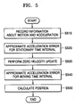
- a method for compensating for an acceleration error including: approximating acceleration errors for the stationary time intervals by each first-order function using acceleration information about the stationary time intervals; performing zero velocity updates to correct the accelerations for the stationary time intervals; approximating an acceleration error for the moving time interval by a first-order function using the acceleration errors approximated for the stationary time intervals; and subtracting the acceleration error for the moving time interval from the acceleration information and calculating acceleration subjected to error correction for the moving time interval.
- a slope of the acceleration error for the moving time interval is determined using slopes of a first first-order function approximating an acceleration error for a stationary time interval before the moving time interval, and a second first-order function approximating an acceleration error for a stationary time interval after the moving time interval.
- the slope of the acceleration error for the moving time interval is determined using a first first-order function value produced at the moment when the system undergoes a transition from a stationary state to a moving state and a second first-order function value produced at the moment when the system undergoes a transition from a moving state to a stationary state.
- a method for calculating the position of an INS including: recording acceleration information of the INS and information about stationary time intervals when the INS is stationary and a moving time interval when the INS is moving, determined according to the acceleration information; approximating acceleration errors for the stationary time intervals by each first-order function using the acceleration information for the stationary time intervals, and performing zero velocity updates to correct the accelerations for the stationary time intervals; approximating an acceleration error for the moving time interval by a first-order function using the acceleration errors for the stationary time intervals, and calculating an acceleration subjected to error correction for the moving time interval; and calculating the position of the INS using the corrected accelerations for the stationary and moving time intervals.
- an inertial navigation system includes a sensor portion 310 comprising acceleration sensors and gyroscopes that measure 3 axis acceleration and 3 axis angular velocity, respectively, along three axes, a motion detector 320 that determines whether the INS including the sensor portion 310 is stationary, an acceleration error model determiner 330 that determines a linear model for an acceleration sensor error, and a position calculator 340 that calculates an actual position of the INS from an acceleration compensated using the linear model.
- the motion detector 320 if in direct control of the motion of the INS, simply outputs the time when the INS including the sensor portion 310 is moving or stationary.
- the motion detector 320 determines that the INS is stationary if a value measured by the sensor portion 310 is less than a predetermined threshold and determines that the INS is moving if the measured value is greater than the threshold.
- the acceleration error model determiner 330 includes first and second information recorders 331 and 333, a zero velocity compensator 337, and first and second acceleration error calculators 335 and 339.
- the first information recorder 331 records acceleration information while the INS is stationary, i.e., before it starts moving or after it stops moving.
- the first acceleration error calculator 335 approximates the acceleration for a time interval when the INS is stationary ("stationary time interval") by a linear function and calculates an error in the acceleration for the stationary time interval.
- the zero velocity compensator 337 corrects for the INS velocity and acceleration for the stationary time interval.
- the second information recorder 333 records acceleration information measured while the INS is moving.
- the second acceleration error calculator 339 calculates an acceleration for a time interval when the INS is moving ("moving time interval") corrected by using the approximated acceleration error and the corrected zero velocity corresponding to the stationary time interval.
- the position calculator 340 performs a double integral of the corrected acceleration calculated by the acceleration error model determiner 330 and calculates an INS position.
- FIG. 4 shows acceleration in an absolute coordinate system measured by the sensor 310.
- the theoretical background of the present invention will now be described with reference to FIG. 4.
- the present invention is proposed to overcome the limit posed by conventional technology where an acceleration error is modeled as a constant; the present invention proposes additional conditions for modeling an acceleration error derived while the INS is moving as a first-order equation.
- the acceleration error is not constant during a stationary time interval, but increases or decreases linearly as shown in FIG. 4, the way in which an acceleration error changes during a moving time interval cannot be known.
- n+1 coefficients must be determined, which requires n+1 conditional expressions. Since the only intuitively known condition is that the velocity is 0 when the INS is stationary, the present invention provides additional conditions that allow an acceleration sensor measurement error in an absolute coordinate system to be modeled as a first-order expression in the form at+b.
- FIG. 5 is a flowchart illustrating a method for compensating for an acceleration error according to a preferred embodiment of the present invention
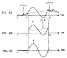
- FIG. 6 shows accelerations measured and corrected in each step of the method illustrated in FIG. 5.
- step S510 when an INS starts to operate, accelerations along three axes sensed by the acceleration sensors contained in the sensor portion 310, and motion information detected by the motion detector 320, are input to the first and second information recorders 331 and 333.
- the first information recorder 331 records the input accelerations along three axes corresponding to a time interval when the motion detector 320 senses that the INS is stationary, and outputs the recorded acceleration information to the first acceleration error calculator 335 and the zero velocity compensator 337.
- the second information recorder 333 records the input accelerations along three axes for a time interval t between t1 and t2 when the motion detector 320 senses that the INS is moving, and outputs the recorded accelerations to the second acceleration error calculator 339.
- step S520 the first acceleration error calculator 335 performs a linear regression on the accelerations recorded for a time interval between 0 and t1 before the INS starts to move to obtain a straight line a 1 t+b 1 , linearly approximated as shown in FIG. 6A.
- the first acceleration error calculator 335 performs a linear regression on the accelerations recorded for a time interval after t2 when the INS stops moving to obtain a straight line a 2 t+b 2 , linearly approximated as shown in FIG. 6A.
- the approximated straight lines are output to the second acceleration error calculator 339.
- step S530 the zero velocity compensator 337 performs a zero velocity update (ZUPT) on velocities for stationary time intervals received from the first information recorder 331. That is, as described above, it can be known intuitively that the INS has 0 velocity during the stationary time intervals between 0 and t1 and after t2, and thus has 0 accelerations during the same intervals. Thus, the zero velocity compensator 337 corrects the accelerations during the stationary time intervals to 0 as shown in FIG. 6A and then outputs the corrected acceleration information to the second error acceleration calculator 339.
- ZUPT zero velocity update
- step S540 the second error acceleration calculator 339 approximates an acceleration error at+b in the moving time interval using the approximated acceleration errors a 1 t+b 1 and a 2 t+b 2 . Then, the second error acceleration calculator 339 determines slope a and constant b of the approximated acceleration error for the moving time interval.
- Equation (4) can be rearranged to isolate constant b as shown in Equation (5):
- Equation (3) The acceleration error at+b for the moving time interval between t1 and t2 obtained by Equations (3) and (5) is shown in FIG. 6B along with the curve of an acceleration A', subjected to a ZUPT.
- FIG. 6C shows the acceleration curve subjected to ZUPT and the error correction for the moving time interval.
- the position calculator 340 performs a double integral on the corrected acceleration A" received from the second acceleration error calculator 339 and calculates a position P of the INS.
- FIGS. 7A and 7B show a performance comparison between a handwriting recovery device using a conventional INS and a handwriting recovery device using an INS performing an acceleration error compensation method according to the present invention.
- an upper picture of FIG. 7A shows a position locus calculated by conventional technology and a lower picture shows one calculated by the present invention.
- the circles calculated by the present invention overlap one another more than the circles calculated by the conventional technology.
- FIG. 7B shows a position locus calculated by conventional technology and a lower part of FIG. 7B shows a position locus calculated by the present invention.
- the position locus calculated by the present invention is more similar to the word "sait" in handwriting than the position locus calculated by the conventional technology.
- the invention can also be embodied as computer readable codes on a computer readable recording medium.
- the computer readable recording medium is any data storage device that can store data, which can be thereafter be read by a computer system. Examples of the computer readable recording medium include read-only memory (ROM), random-access memory (RAM), CD-ROM, magnetic tape, floppy disks, optical data storage devices, and carrier waves (such as data transmission over the Internet).
- ROM read-only memory
- RAM random-access memory
- CD-ROM compact discs
- magnetic tape magnetic tape
- floppy disks optical data storage devices
- carrier waves such as data transmission over the Internet
- the present invention overcomes the limit of conventional technology, which treats acceleration error as a constant, and allows the acceleration error to be modelled more closely to the actual acceleration error, thus eliminating acceleration errors intrinsic to the INS more effectively while enabling accurate calculation of the position and orientation of a moving three-dimensional object.
Abstract
Description
- The present invention relates to a method and apparatus for correcting acceleration errors, and more particularly, to a method and apparatus for compensating for an error in position determined by an inertial navigation system (INS), an INS therefor, and a method, which calculates a position in the INS.
- Typically, inertial sensors including tri-axial acceleration sensors and tri-axial gyroscopes are used to measure the position and orientation of a moving object of interest in a three-dimensional space. While INS orientation is obtained by solving differential equations to integrate angular velocities measured by the gyroscopes, position is obtained by removing gravity components from accelerations measured by the acceleration sensors, taking into account the INS orientation, and then calculating double integrals of the accelerations with respect to time. In this case, since INS orientation error derived from error in the gyroscope measurement increases with time, errors in the accelerations from which the gravity components has been removed also increase with time.
- Thus, position errors of the INS due to errors in the acceleration sensor measurement and in the gyroscope measurement grow in proportion to the square of time and the cube of time, respectively. Since the INS errors dramatically increase over time in this way, it is very hard to calculate the position over a relatively long period of time using inertial sensors. The solution to overcome this problem is to correct errors in the acceleration sensors and gyroscopes, which is known in the art. Conventional methods for correcting errors in acceleration sensors will now be examined.
- When the INS makes frequent stops during movement, zero velocity updates (ZUPTs or ZVUs), coordinate updates (CUPTs), and orientation updates, are widely used to correct sensor errors. The ZUPTs are processes to reset a velocity of the INS to zero if the INS is detected to be stationary. The CUPTs are performed to reset an origin, when the INS reaches a predetermined position, to the predetermined position. Likewise, the orientation is reset an orientation at the origin, when the INS takes a predetermined orientation, to the predetermined orientation. These methods can be performed in real time but only allow corrections at specific moments. Thus, errors begin to accumulate again after the corrections are performed. As shown in FIG. 1, when an INS stops again after ZUPTs are performed to correct velocity errors while the INS is held still, the velocity does not return to zero, which means that velocity errors increase over time until the velocity errors get re-corrected.
- To overcome this problem, U.S. Patent No. 6,292,751 discloses a method for correcting acceleration errors caused while an INS is in motion. This method assumes acceleration errors are constant. An acceleration error is calculated, under a condition that a velocity is zero at the time when the INS starts to move and stops. Then, the error is subtracted from the measured acceleration and the resulting value is doubly integrated with respect to time in order to determine the position. FIG. 2 shows a process of compensating for velocity errors through acceleration error correction.
- Referring to FIG. 2, the INS starts to move at time t1 and stops at time t2. This method assumes that an acceleration error during motion of INS is constant. FIG. 2A shows a measured acceleration A of the INS and an acceleration error d indicated by a dotted line. As shown in FIG. 2B, a velocity, which is obtained by integrating the acceleration A, is appeared as a first-order function. Since a velocity of the INS is 0 at time t1 before starting to move, the velocity of the INS at time t1 can be corrected to 0-as shown in FIG. 2C. Since the velocity is 0 at time t2, a velocity error within an interval between t1 and t2 indicated by the dotted line is subtracted from the velocity depicted by a solid line to produce the one shown in FIG. 2D. The resulting corrected velocity can be integrated to yield a position. However, since it is assumed that an acceleration error is constant, large discrepancies get occurred between the calculated position and the actual position.
- It is the object of the present invention to provide a method and apparatus for compensating for errors in acceleration sensors by modeling the errors in a novel scheme, an inertial navigation system (INS), and a method therefor which employs the same for calculating accurate position and orientation.
- This object is solved by the subject matter of the independent claims.
- Preferred embodiments are defined in the dependent claims.
- According to an aspect of the present invention, there is provided an apparatus for compensating for an acceleration error including: a first acceleration error calculator that approximates acceleration information for a stationary time interval when a system is stationary by first-order functions in order to calculate acceleration errors for the stationary time interval; a zero velocity compensator that compensates system velocities for the stationary time intervals and accelerations derived from the velocities; and a second acceleration error calculator that calculates an acceleration error for a moving time interval when the system is moving using the approximated acceleration errors for the stationary time intervals and outputs an acceleration subjected to error correction for the moving time interval using the acceleration error and measured acceleration for the moving time interval and the corrected accelerations for-the stationary time intervals.
- Here, the second acceleration error calculator may determine a slope of the acceleration error for the moving time interval using slopes of a first first-order function approximating an acceleration error for a stationary time interval before the moving time interval, and a second first-order function approximating an acceleration error for a stationary time interval after the moving time interval. That is, the second acceleration error calculator may determine the slope of the acceleration error for the moving time interval using a first first-order function value produced at the moment when the system undergoes a transition from a stationary state to a moving state and a second first order function value- produced at the moment when the system undergoes a transition from a moving state to a stationary state.
- According to another aspect of the present invention, there is provided an INS including: a motion detector that detects the motion of the INS and outputs information on stationary time intervals during which the INS is stationary and a moving time interval during which the INS is moving; a sensor portion that measures accelerations of the INS for the stationary time intervals and moving time interval, respectively; an error model determiner that determines an acceleration error corresponding to the moving time interval using accelerations measured during the stationary time intervals and outputs an acceleration subjected to correction of the acceleration error for the moving time interval; and a position calculator that integrates the corrected acceleration for the moving time interval and outputs the position of the INS.
- According to another aspect of the present invention, there is provided a method for compensating for an acceleration error including: approximating acceleration errors for the stationary time intervals by each first-order function using acceleration information about the stationary time intervals; performing zero velocity updates to correct the accelerations for the stationary time intervals; approximating an acceleration error for the moving time interval by a first-order function using the acceleration errors approximated for the stationary time intervals; and subtracting the acceleration error for the moving time interval from the acceleration information and calculating acceleration subjected to error correction for the moving time interval.
- In the approximating of the acceleration error for the moving time interval, a slope of the acceleration error for the moving time interval is determined using slopes of a first first-order function approximating an acceleration error for a stationary time interval before the moving time interval, and a second first-order function approximating an acceleration error for a stationary time interval after the moving time interval. Altematively, the slope of the acceleration error for the moving time interval is determined using a first first-order function value produced at the moment when the system undergoes a transition from a stationary state to a moving state and a second first-order function value produced at the moment when the system undergoes a transition from a moving state to a stationary state.
- According to another aspect of the present invention, there is provided a method for calculating the position of an INS including: recording acceleration information of the INS and information about stationary time intervals when the INS is stationary and a moving time interval when the INS is moving, determined according to the acceleration information; approximating acceleration errors for the stationary time intervals by each first-order function using the acceleration information for the stationary time intervals, and performing zero velocity updates to correct the accelerations for the stationary time intervals; approximating an acceleration error for the moving time interval by a first-order function using the acceleration errors for the stationary time intervals, and calculating an acceleration subjected to error correction for the moving time interval; and calculating the position of the INS using the corrected accelerations for the stationary and moving time intervals.
- The above and other features and advantages of the present invention will. become more apparent by describing in detail exemplary embodiments thereof with reference to the attached drawings in which:
- FIG. 1 is a graph illustrating a conventional zero velocity update used in an inertial navigation system (INS);
- FIG. 2 illustrates a process of compensating for velocity errors using a conventional acceleration error correction technique;
- FIG. 3 is a block diagram showing the configuration of an INS using an acceleration error compensation method according to a preferred embodiment of the present invention;
- FIG. 4 shows an acceleration in an absolute coordinate system measured by
the
sensor portion 310 shown in FIG. 3; - FIG. 5 is a flowchart illustrating a method for compensating for an acceleration error according to a preferred embodiment of the present invention;
- FIG. 6 shows accelerations measured and corrected in each step of the method illustrated in FIG. 5; and
- FIGS. 7A and 7B show a performance comparison between a handwriting recovery device using a conventional INS and a handwriting recovery device using an INS performing an acceleration error compensation method according to the present invention.
-
- Referring to FIG. 3, an inertial navigation system (INS) according to the present invention includes a
sensor portion 310 comprising acceleration sensors and gyroscopes that measure 3 axis acceleration and 3 axis angular velocity, respectively, along three axes, amotion detector 320 that determines whether the INS including thesensor portion 310 is stationary, an acceleration error model determiner 330 that determines a linear model for an acceleration sensor error, and aposition calculator 340 that calculates an actual position of the INS from an acceleration compensated using the linear model. Themotion detector 320, if in direct control of the motion of the INS, simply outputs the time when the INS including thesensor portion 310 is moving or stationary. Otherwise, if the motion of the INS is controlled by an external factor, themotion detector 320 determines that the INS is stationary if a value measured by thesensor portion 310 is less than a predetermined threshold and determines that the INS is moving if the measured value is greater than the threshold. - The acceleration
error model determiner 330 includes first andsecond information recorders velocity compensator 337, and first and secondacceleration error calculators first information recorder 331 records acceleration information while the INS is stationary, i.e., before it starts moving or after it stops moving. The firstacceleration error calculator 335 approximates the acceleration for a time interval when the INS is stationary ("stationary time interval") by a linear function and calculates an error in the acceleration for the stationary time interval. The zerovelocity compensator 337 corrects for the INS velocity and acceleration for the stationary time interval. Thesecond information recorder 333 records acceleration information measured while the INS is moving. The secondacceleration error calculator 339 calculates an acceleration for a time interval when the INS is moving ("moving time interval") corrected by using the approximated acceleration error and the corrected zero velocity corresponding to the stationary time interval. Theposition calculator 340 performs a double integral of the corrected acceleration calculated by the acceleration error model determiner 330 and calculates an INS position. - FIG. 4 shows acceleration in an absolute coordinate system measured by the
sensor 310. The theoretical background of the present invention will now be described with reference to FIG. 4. The present invention is proposed to overcome the limit posed by conventional technology where an acceleration error is modeled as a constant; the present invention proposes additional conditions for modeling an acceleration error derived while the INS is moving as a first-order equation. - Conventionally, when measured acceleration and acceleration error in an absolute coordinate system are denoted by A and d, respectively, actual acceleration  can be defined by Equation (1):
- However, an experiment was conducted to reveal that an actual acceleration error is not constant like in Equation (1), but linearly changes within a few seconds. Three curves in FIG. 4 represent accelerations measured in an absolute coordinate system, along x, y, and z axes, when the INS starts to move after 2 seconds and stops after 8 seconds. According to INS theory, since integration must be performed to calculate an acceleration in a absolute coordinate system from accelerations and angular velocities measured by an inertial sensor system along three axes, errors in the acceleration in the absolute coordinate system accumulate with time even when the INS is completely stationary. As is evident from the curves in FIG. 4, the acceleration is not 0 during intervals between 0 and 2 seconds and between 8 and 10 seconds when the INS is actually stationary.
- While the acceleration error is not constant during a stationary time interval, but increases or decreases linearly as shown in FIG. 4, the way in which an acceleration error changes during a moving time interval cannot be known. To model the error as an n-th order polynomial, n+1 coefficients must be determined, which requires n+1 conditional expressions. Since the only intuitively known condition is that the velocity is 0 when the INS is stationary, the present invention provides additional conditions that allow an acceleration sensor measurement error in an absolute coordinate system to be modeled as a first-order expression in the form at+b. As a result, the relationship between the actual acceleration  and measured acceleration A is defined by Equation (2), thus providing a method for determining an acceleration that more closely approximates the actual acceleration:
- FIG. 5 is a flowchart illustrating a method for compensating for an acceleration error according to a preferred embodiment of the present invention, and FIG. 6 shows accelerations measured and corrected in each step of the method illustrated in FIG. 5.
- In step S510, when an INS starts to operate, accelerations along three axes sensed by the acceleration sensors contained in the
sensor portion 310, and motion information detected by themotion detector 320, are input to the first andsecond information recorders first information recorder 331 records the input accelerations along three axes corresponding to a time interval when themotion detector 320 senses that the INS is stationary, and outputs the recorded acceleration information to the firstacceleration error calculator 335 and the zerovelocity compensator 337. Thesecond information recorder 333 records the input accelerations along three axes for a time interval t between t1 and t2 when themotion detector 320 senses that the INS is moving, and outputs the recorded accelerations to the secondacceleration error calculator 339. - In step S520, the first
acceleration error calculator 335 performs a linear regression on the accelerations recorded for a time interval between 0 and t1 before the INS starts to move to obtain a straight line a1t+b1, linearly approximated as shown in FIG. 6A. Similarly, the firstacceleration error calculator 335 performs a linear regression on the accelerations recorded for a time interval after t2 when the INS stops moving to obtain a straight line a2t+b2, linearly approximated as shown in FIG. 6A. The approximated straight lines are output to the secondacceleration error calculator 339. - In step S530, the zero
velocity compensator 337 performs a zero velocity update (ZUPT) on velocities for stationary time intervals received from thefirst information recorder 331. That is, as described above, it can be known intuitively that the INS has 0 velocity during the stationary time intervals between 0 and t1 and after t2, and thus has 0 accelerations during the same intervals. Thus, the zerovelocity compensator 337 corrects the accelerations during the stationary time intervals to 0 as shown in FIG. 6A and then outputs the corrected acceleration information to the seconderror acceleration calculator 339. - In step S540, the second
error acceleration calculator 339 approximates an acceleration error at+b in the moving time interval using the approximated acceleration errors a1t+b1 and a2t+b2. Then, the seconderror acceleration calculator 339 determines slope a and constant b of the approximated acceleration error for the moving time interval. - A method for determining an approximated acceleration error derived during a moving time interval according to a first embodiment of the present invention will now be described. In the first embodiment, the second
acceleration error calculator 339 determines a slope a of the approximated acceleration error at+b in an absolute coordinate system using slopes of the approximated acceleration errors for stationary time intervals as shown in Equation (3): - Meanwhile, since the INS velocity is 0 at times t1 and t2, the constant b can be obtained from the condition shown in Equation (4), i.e., the condition that an integral of the actual acceleration  obtained after correcting errors in the measured acceleration shown in FIG. 6 between t1 and t2 should be equal to 0.Equation (4) can be rearranged to isolate constant b as shown in Equation (5):


- The acceleration error at+b for the moving time interval between t1 and t2 obtained by Equations (3) and (5) is shown in FIG. 6B along with the curve of an acceleration A', subjected to a ZUPT.
- The second
acceleration error calculator 339 subtracts the calculated acceleration error at+b from the acceleration corresponding to the moving time interval input from thesecond information recorder 333 and then determines a corrected acceleration A" in the absolute coordinate system using Equation (6): - Meanwhile, the second
acceleration error calculator 339 according to a second preferred embodiment of the present invention determines the slope a of the acceleration error using acceleration errors a1t1+b1 and a2t2+b2 at time t1 and t2, instead of using Equation (3) above. That is, the secondacceleration error calculator 339 determines the slope a of the approximated acceleration error straight line using Equation (7):t t t - Every process in the second embodiment, except the process of calculating the slope a of the acceleration error straight line, is the same as in the first embodiment.
- The
position calculator 340 performs a double integral on the corrected acceleration A" received from the secondacceleration error calculator 339 and calculates a position P of the INS.
- FIGS. 7A and 7B show a performance comparison between a handwriting recovery device using a conventional INS and a handwriting recovery device using an INS performing an acceleration error compensation method according to the present invention. When the same four circles are drawn in the air using a handwriting recovery device, an upper picture of FIG. 7A shows a position locus calculated by conventional technology and a lower picture shows one calculated by the present invention. As is evident from FIG. 7A, the circles calculated by the present invention overlap one another more than the circles calculated by the conventional technology.
- When a word "sait" is drawn in the air using a handwriting recovery device, an upper part of FIG. 7B shows a position locus calculated by conventional technology and a lower part of FIG. 7B shows a position locus calculated by the present invention. As is evident from FIG. 7B, the position locus calculated by the present invention is more similar to the word "sait" in handwriting than the position locus calculated by the conventional technology.
- The invention can also be embodied as computer readable codes on a computer readable recording medium. The computer readable recording medium is any data storage device that can store data, which can be thereafter be read by a computer system. Examples of the computer readable recording medium include read-only memory (ROM), random-access memory (RAM), CD-ROM, magnetic tape, floppy disks, optical data storage devices, and carrier waves (such as data transmission over the Internet). The computer readable recording medium can also be distributed over a network of coupled computer systems so that the computer readable code is stored and executed in a de-centralized fashion.
- While this invention has been particularly shown and described with reference to preferred embodiments thereof, it will be understood by those skilled in the art that various changes in form and details may be made therein without departing from the spirit and scope of the invention as defined by the appended claims and their equivalents.
- The present invention overcomes the limit of conventional technology, which treats acceleration error as a constant, and allows the acceleration error to be modelled more closely to the actual acceleration error, thus eliminating acceleration errors intrinsic to the INS more effectively while enabling accurate calculation of the position and orientation of a moving three-dimensional object.
Claims (29)
- An inertial navigation system comprising:a motion detector that detects the motion of the inertial navigation system and outputs information on stationary time intervals during which the inertial navigation system is stationary and a moving time interval during which the inertial navigation system is moving;a sensor portion that measures accelerations of the inertial navigation system for the stationary time intervals and moving time interval, respectively;an error model determiner that determines an acceleration error corresponding to the moving time interval using accelerations measured during the stationary time intervals and outputs an acceleration subjected to correction of the acceleration error for the moving time interval; anda position calculator that integrates the corrected acceleration for the moving time interval and outputs the position of the inertial navigation system.
- The inertial navigation system as claimed in claim 1, wherein the error model determiner approximates acceleration errors for the stationary time intervals and the acceleration error for the moving time interval by first-order functions, each having a slope and an intercept.
- The inertial navigation system as claimed in claim 2, wherein the error model determiner determines the slope of the acceleration error for the moving time interval using slopes of a first first-order function approximating an acceleration error for a stationary time interval before the moving time interval, and a second first-order function approximating an acceleration error for a stationary time interval after the moving time interval.
- The inertial navigation system as claimed in claim 3, wherein the error model determiner determines the slope of the acceleration error for the moving time interval by averaging the slopes of the first and second first-order functions.
- The inertial navigation system as claimed in claim 2, wherein the error model determiner determines the slope of the acceleration error for the moving time interval using a first first-order function value produced at the moment when the inertial navigation system undergoes a transition from a stationary state to a moving state, and a second first-order function value produced at the moment when the inertial navigation system undergoes a transition from a moving state to a stationary state.
- The inertial navigation system as claimed in claim 5, wherein the error model determiner determines the slope of the acceleration error for the moving time interval by dividing the difference between the values of the first and second first-order functions by the moving time interval.
- The inertial navigation system as claimed in any one of claims 2 through 6, wherein the intercept of the first-order function by which the inertial navigation system acceleration error for the moving time interval is modeled is calculated from a condition that an integral of the result of subtracting the measured acceleration from the acceleration error over the moving time interval is equal to zero.
- The inertial navigation system as claimed in one of claims 1 to 7, wherein the error model determiner comprises:a first acceleration error calculator that approximates the accelerations for the stationary time intervals by first-order functions in order to calculate acceleration errors for the stationary time intervals;a zero velocity compensator that compensates inertial navigation system velocities and accelerations derived from the velocities for the stationary time intervals; anda second acceleration error calculator that calculates the acceleration error for the moving time interval using the approximated acceleration errors for the stationary time intervals and outputs the acceleration subjected to error correction for the moving time interval using the acceleration error and measured acceleration for the moving time interval and the corrected accelerations for the stationary time intervals.
- The inertial navigation system as claimed in one of claims 1 to 8, wherein the motion detector outputs a time interval when the acceleration measured by the sensor portion is greater than a predetermined threshold as the moving time interval.
- An apparatus for compensating for an acceleration error using received information about a stationary time intervals when a system is stationary and a moving time interval when the system is moving and measured acceleration information for each time interval, the apparatus comprising:a first acceleration error calculator that approximates the acceleration information for the stationary time intervals by first-order functions in order to calculate acceleration errors for the stationary time interval;a zero velocity compensator that compensates system velocities for the stationary time intervals and accelerations derived from the velocities; anda second acceleration error calculator that calculates an acceleration error for the moving time interval using the approximated acceleration errors for the stationary time intervals and outputs acceleration subjected to error correction for the moving time interval using the acceleration error and measured acceleration for the moving time interval and the corrected accelerations for the stationary time intervals.
- The apparatus as claimed in claim 10, wherein the second acceleration error calculator determines a slope of the acceleration error for the moving time interval using slopes of a first first-order function approximating an acceleration error for a stationary time interval before the moving time interval, and a second first-order function approximating an acceleration error for a stationary time interval after the moving time interval.
- The apparatus as claimed in claim 11, wherein the second acceleration error calculator determines the slope of the acceleration error for the moving time interval by averaging the slopes of the first and second first-order functions.
- The apparatus as claimed in claim 11, wherein the second acceleration error calculator determines the slope of the acceleration error for the moving time interval using a first first-order function value produced at the moment when the system undergoes a transition from a stationary state to a moving state, and a second first-order function value produced at the moment when the system undergoes a transition from a moving state to a stationary state.
- The apparatus as claimed in claim 13, wherein the second acceleration calculator determines the slope of the acceleration error for the moving time interval by dividing the difference between the values of the first and second first-order functions by the moving time interval.
- The apparatus as claimed in one of claims 10 to 14, wherein the second acceleration error calculator calculates the corrected acceleration for the moving time interval by subtracting the acceleration error from the measured acceleration for the moving-time interval.
- The apparatus as claimed in any one of claims 11 through 15, wherein an intercept of the first-order function by which the acceleration error of the system for the moving time interval is modeled is calculated from a condition that an integral of the result of subtracting the measured acceleration from the acceleration error over the moving time interval is equal to zero.
- A method for calculating a position of an inertial navigation system, the method comprising:recording acceleration information of the inertial navigation system and information about stationary time intervals when the inertial navigation system is stationary and a moving time interval when the inertial navigation system is moving, determined according to the acceleration information;approximating acceleration errors for the stationary time intervals by each first-order function using the acceleration information for the stationary time intervals, and performing zero velocity updates to correct the accelerations for the stationary time intervals;approximating an acceleration error for the moving time interval by a first-order function using the acceleration errors for the stationary time intervals, and calculating an acceleration subjected to error correction for the moving time interval; andcalculating the position of the inertial navigation system using the corrected accelerations for the stationary and moving time intervals.
- The method as claimed in claim 17, wherein in the calculating of the acceleration for the moving time interval, a slope of the acceleration error for the moving time interval is determined using slopes of a first first-order function approximating an acceleration error for a stationary time interval before the moving time interval, and a second first-order function approximating an acceleration error for a stationary time interval after the moving time interval.
- The method as claimed in claim 18, wherein in the calculating of the acceleration for the moving time interval, the slope of the acceleration error for the moving time interval is determined by averaging the slopes of the first and second first-order functions.
- The method as claimed in claim 17, wherein in the calculating of the acceleration for the moving time interval, the slope of the acceleration error for the moving time interval is determined using a first first-order function value produced at the moment when the system undergoes a transition from a stationary state to a moving state and a second first-order function value produced at the moment when the system undergoes a transition from a moving state to a stationary state.
- The method as claimed in claim 17, wherein in the calculating of the acceleration for the moving time interval, an intercept of the first-order function by which the acceleration error for the moving time interval is modeled is calculated from a condition that an integral of the result of subtracting the measured acceleration from the acceleration error over the moving time interval is equal to zero.
- The method as claimed in one of claims 17 to 21, wherein in the recording of the information about the time intervals, a time interval when the measured acceleration is greater than a predetermined threshold is output as the moving time interval.
- A recording medium on which the method for calculating the position of the inertial navigation system according to any one as claimed in claims 17 through 22 is recorded as a program code that can be read and executed by a computer.
- A method for compensating for an acceleration error using received information about stationary time intervals when a system is stationary, a moving time interval when the system is moving and measured acceleration information for each time interval, the method comprising:approximating acceleration errors for the stationary time intervals by each first-order function using the acceleration information about the stationary time intervals;performing zero velocity updates to correct the accelerations for the stationary time intervals;approximating an acceleration error for the moving time interval by a first-order function, using the acceleration errors approximated for the stationary time intervals; andsubtracting the acceleration error for the moving time interval from the acceleration information and calculating an acceleration subjected to error correction for the moving time interval.
- The method as claimed in claim 24, wherein in the approximating of the acceleration error for the moving time interval, a slope of the acceleration error for the moving time interval is determined using slopes of a first first-order function approximating an acceleration error for a stationary time interval before the moving time interval, and a second first-order function approximating an acceleration error for a stationary time interval after the moving time interval.
- The method as claimed in claim 25, wherein in the approximating of the acceleration error for the moving time interval, the slope of the acceleration error for the moving time interval is determined by averaging the slopes of the first and second first-order functions.
- The method as claimed in claim 24, wherein in the approximating of the acceleration error for the moving time interval, the slope of the acceleration error for the moving time interval is determined using values of a first first-order function value produced at the moment when the system undergoes a transition from a stationary state to a moving state and a second first-order function value produced at the moment when the system undergoes a transition from a moving state to a stationary state.
- The method as claimed in claim 27, wherein in the approximating of the acceleration error for the moving time interval, the slope of the acceleration error for the moving time interval is determined by dividing the difference between the values of the first and second first-order functions by the moving time interval.
- A recording medium on which the method for compensating for an acceleration error according to any one of claims 24 through 28 is recorded as a program code that can be read and executed by a computer.
Applications Claiming Priority (2)
| Application Number | Priority Date | Filing Date | Title |
|---|---|---|---|
| KR2003038682 | 2003-06-16 | ||
| KR10-2003-0038682A KR100480793B1 (en) | 2003-06-16 | 2003-06-16 | Method and apparatus for compensating the acceleration error and inertial navigation system using thereof |
Publications (3)
| Publication Number | Publication Date |
|---|---|
| EP1489381A2 true EP1489381A2 (en) | 2004-12-22 |
| EP1489381A3 EP1489381A3 (en) | 2005-08-31 |
| EP1489381B1 EP1489381B1 (en) | 2008-05-28 |
Family
ID=33411752
Family Applications (1)
| Application Number | Title | Priority Date | Filing Date |
|---|---|---|---|
| EP04014129A Expired - Fee Related EP1489381B1 (en) | 2003-06-16 | 2004-06-16 | Method and apparatus for compensating for acceleration errors and inertial navigation system employing the same |
Country Status (5)
| Country | Link |
|---|---|
| US (1) | US7280916B2 (en) |
| EP (1) | EP1489381B1 (en) |
| JP (1) | JP3947531B2 (en) |
| KR (1) | KR100480793B1 (en) |
| DE (1) | DE602004014067D1 (en) |
Cited By (9)
| Publication number | Priority date | Publication date | Assignee | Title |
|---|---|---|---|---|
| WO2007015137A1 (en) * | 2005-08-01 | 2007-02-08 | Toyota Jidosha Kabushiki Kaisha | Zero-point correction apparatus and method for an angular speed sensor |
| FR2915569A1 (en) * | 2007-04-26 | 2008-10-31 | Parrot Sa | Sensor e.g. accelerometer, calibrating method for e.g. drone, involves summing and integrating values to obtain total result, dividing result by known value to obtain estimation of bias, and calibrating sensor using bias |
| EP2199807A2 (en) | 2008-12-19 | 2010-06-23 | Panasonic Corporation | Sensor device |
| WO2015173408A1 (en) * | 2014-05-15 | 2015-11-19 | Stabilo International Gmbh | Electronic pen implementing sensor drift compensation |
| RU2577567C1 (en) * | 2015-01-22 | 2016-03-20 | Акционерное общество "Концерн "Центральный научно-исследовательский институт "Электроприбор" | Method for strapdown inertial navigation on micromechanical sensitive elements |
| GB2543916A (en) * | 2015-09-11 | 2017-05-03 | Bae Systems Plc | Inertial sensor data correction |
| RU2660160C1 (en) * | 2017-08-01 | 2018-07-05 | Михаил Тимурович Балдычев | Method of determining the motion parameters of an air object by the dynamic radio monitoring system |
| RU2677852C1 (en) * | 2018-01-22 | 2019-01-22 | Российская Федерация, от имени которой выступает Министерство обороны Российской Федерации | Method for determining location of mobile source of radio emission, transferring its coordinates with unknown displacement, two-positioning system with high-dimensional measurement point |
| RU2681836C1 (en) * | 2018-02-13 | 2019-03-13 | федеральное государственное автономное образовательное учреждение высшего образования "Казанский (Приволжский) федеральный университет" (ФГАОУ ВО КФУ) | Method for determining spatial coordinates and angular position of a remote object |
Families Citing this family (31)
| Publication number | Priority date | Publication date | Assignee | Title |
|---|---|---|---|---|
| US7487043B2 (en) * | 2004-08-30 | 2009-02-03 | Adams Phillip M | Relative positioning system |
| JP4615287B2 (en) * | 2004-11-01 | 2011-01-19 | 東京計器株式会社 | Azimuth and orientation detection device |
| KR100643304B1 (en) * | 2005-02-15 | 2006-11-10 | 삼성전자주식회사 | Apparatus and method for correcting inertia measurement unit and recording medium for recording the method |
| EP1886202A4 (en) | 2005-06-01 | 2011-09-21 | Allstate Insurance Co | Motor vehicle operating data collection and analysis |
| KR101185144B1 (en) * | 2006-01-24 | 2012-09-24 | 삼성전자주식회사 | Method and apparatus for estimating 2-dimension trajectory of a gesture |
| KR100768032B1 (en) * | 2006-02-21 | 2007-10-19 | 포스데이타 주식회사 | Decoder and Decoding Method |
| JP4781300B2 (en) * | 2007-03-01 | 2011-09-28 | アルパイン株式会社 | Position detection apparatus and position detection method |
| US20080291042A1 (en) * | 2007-05-23 | 2008-11-27 | Honeywell International Inc. | Inertial measurement unit localization technique for sensor networks |
| JP4842885B2 (en) | 2007-05-23 | 2011-12-21 | トヨタ自動車株式会社 | In-vehicle device control system and vehicle |
| JP4582116B2 (en) * | 2007-06-06 | 2010-11-17 | ソニー株式会社 | INPUT DEVICE, CONTROL DEVICE, CONTROL SYSTEM, CONTROL METHOD AND ITS PROGRAM |
| FR2925670B1 (en) * | 2007-12-21 | 2010-01-15 | Thales Sa | INVERTIBLE CENTRAL AUTONOMOUS ALIGNMENT METHOD FOR INSTRUMENT OF INSTRUMENT THAT CAN EQUIP AN AIRCRAFT AND INSTRUMENT OF INSTRUMENT USING SUCH A METHOD |
| US8224575B2 (en) * | 2008-04-08 | 2012-07-17 | Ensco, Inc. | Method and computer-readable storage medium with instructions for processing data in an internal navigation system |
| US8996332B2 (en) | 2008-06-24 | 2015-03-31 | Dp Technologies, Inc. | Program setting adjustments based on activity identification |
| TWI457793B (en) * | 2008-08-08 | 2014-10-21 | Ind Tech Res Inst | Real-time motion recognition method and inertia sensing and trajectory |
| US8311740B2 (en) * | 2010-01-28 | 2012-11-13 | CSR Technology Holdings Inc. | Use of accelerometer only data to improve GNSS performance |
| JP5948011B2 (en) | 2010-11-19 | 2016-07-06 | セイコーエプソン株式会社 | Motion analysis device |
| JP6254846B2 (en) | 2011-02-17 | 2017-12-27 | タイト ケア リミテッド | System and method for performing automatic and self-guided medical examinations |
| EP2675351B1 (en) | 2011-02-17 | 2021-06-23 | Tyto Care Ltd. | System, handheld diagnostics device and methods for performing an automatic and remote trained personnel guided non-invasive medical examination |
| JP6094026B2 (en) * | 2011-03-02 | 2017-03-15 | セイコーエプソン株式会社 | Posture determination method, position calculation method, and posture determination apparatus |
| CN102997916B (en) * | 2011-09-15 | 2015-08-05 | 北京自动化控制设备研究所 | A kind of method of autonomous raising positioning and orientation system inertial attitude calculation accuracy |
| RU2493578C1 (en) * | 2012-01-10 | 2013-09-20 | Общество с ограниченной ответственностью "Инновационные технологии" | Device for monitoring vehicle control system sensors |
| JP6222096B2 (en) * | 2012-09-19 | 2017-11-01 | 株式会社ニコン | Electronic device and program |
| KR101337541B1 (en) * | 2012-10-25 | 2013-12-06 | 국방과학연구소 | Vehicle's engine vibration computation by inertial sensors and application for navigation |
| US10231337B2 (en) | 2014-12-16 | 2019-03-12 | Inertial Sense, Inc. | Folded printed circuit assemblies and related methods |
| JP6190423B2 (en) * | 2015-06-30 | 2017-08-30 | ヤフー株式会社 | Estimation apparatus, movement direction estimation method, and movement direction estimation program |
| KR101658473B1 (en) * | 2015-08-03 | 2016-09-22 | 국방과학연구소 | Compensation method of acceleration sensitivity of mems gyroscope |
| JP6407368B2 (en) * | 2017-07-05 | 2018-10-17 | ヤフー株式会社 | Estimation apparatus, movement direction estimation method, and movement direction estimation program |
| CN110887507B (en) * | 2019-10-22 | 2021-05-25 | 中国人民解放军战略支援部队航天工程大学 | Method for quickly estimating all zero offsets of inertial measurement units |
| CN111024126B (en) * | 2019-12-26 | 2022-03-22 | 北京航天控制仪器研究所 | Self-adaptive zero-speed correction method in pedestrian navigation positioning |
| CN114279441B (en) * | 2021-12-15 | 2023-12-29 | 中国科学院深圳先进技术研究院 | Zero-speed interval detection method, pedestrian navigation system and storage medium |
| CN116539069A (en) * | 2023-07-05 | 2023-08-04 | 杭州光粒科技有限公司 | Data correction method, device, equipment and readable storage medium |
Citations (4)
| Publication number | Priority date | Publication date | Assignee | Title |
|---|---|---|---|---|
| DE3443317A1 (en) * | 1984-11-28 | 1986-06-05 | Messerschmitt-Bölkow-Blohm GmbH, 8012 Ottobrunn | Method and device for aligning inertial navigation systems |
| US5789671A (en) * | 1996-08-15 | 1998-08-04 | Fernandez; Manuel | Azimuth misalignment determination in an inertial navigator |
| US6292751B1 (en) * | 2000-02-08 | 2001-09-18 | Bae Systems | Positioning refinement algorithm |
| US20020173910A1 (en) * | 1999-11-29 | 2002-11-21 | Mccall Hiram | Vehicle self-carried positioning method and system thereof |
Family Cites Families (5)
| Publication number | Priority date | Publication date | Assignee | Title |
|---|---|---|---|---|
| US5794078A (en) * | 1995-09-11 | 1998-08-11 | Nikon Corporation | Image movement correction of camera |
| US5874918A (en) * | 1996-10-07 | 1999-02-23 | Lockheed Martin Corporation | Doppler triangulation transmitter location system |
| US5870056A (en) * | 1996-12-05 | 1999-02-09 | Lockheed Martin Corporation | Air-to-air passive location system |
| JPH10307032A (en) | 1997-05-02 | 1998-11-17 | Pioneer Electron Corp | Navigator |
| JP3282547B2 (en) | 1997-06-27 | 2002-05-13 | 株式会社村田製作所 | External force measuring device |
-
2003
- 2003-06-16 KR KR10-2003-0038682A patent/KR100480793B1/en not_active IP Right Cessation
-
2004
- 2004-06-14 JP JP2004175177A patent/JP3947531B2/en not_active Expired - Fee Related
- 2004-06-16 EP EP04014129A patent/EP1489381B1/en not_active Expired - Fee Related
- 2004-06-16 DE DE602004014067T patent/DE602004014067D1/en not_active Expired - Fee Related
- 2004-06-16 US US10/867,767 patent/US7280916B2/en active Active
Patent Citations (4)
| Publication number | Priority date | Publication date | Assignee | Title |
|---|---|---|---|---|
| DE3443317A1 (en) * | 1984-11-28 | 1986-06-05 | Messerschmitt-Bölkow-Blohm GmbH, 8012 Ottobrunn | Method and device for aligning inertial navigation systems |
| US5789671A (en) * | 1996-08-15 | 1998-08-04 | Fernandez; Manuel | Azimuth misalignment determination in an inertial navigator |
| US20020173910A1 (en) * | 1999-11-29 | 2002-11-21 | Mccall Hiram | Vehicle self-carried positioning method and system thereof |
| US6292751B1 (en) * | 2000-02-08 | 2001-09-18 | Bae Systems | Positioning refinement algorithm |
Cited By (14)
| Publication number | Priority date | Publication date | Assignee | Title |
|---|---|---|---|---|
| WO2007015137A1 (en) * | 2005-08-01 | 2007-02-08 | Toyota Jidosha Kabushiki Kaisha | Zero-point correction apparatus and method for an angular speed sensor |
| CN101233390B (en) * | 2005-08-01 | 2011-07-06 | 丰田自动车株式会社 | Zero point correction device of angular velocity sensor |
| FR2915569A1 (en) * | 2007-04-26 | 2008-10-31 | Parrot Sa | Sensor e.g. accelerometer, calibrating method for e.g. drone, involves summing and integrating values to obtain total result, dividing result by known value to obtain estimation of bias, and calibrating sensor using bias |
| EP2199807A2 (en) | 2008-12-19 | 2010-06-23 | Panasonic Corporation | Sensor device |
| EP2199807A3 (en) * | 2008-12-19 | 2010-12-29 | Panasonic Corporation | Sensor device |
| US8393213B2 (en) | 2008-12-19 | 2013-03-12 | Panasonic Corporation | Sensor device |
| WO2015173408A1 (en) * | 2014-05-15 | 2015-11-19 | Stabilo International Gmbh | Electronic pen implementing sensor drift compensation |
| US10146338B2 (en) | 2014-05-15 | 2018-12-04 | Stabilo International Gmbh | Electronic pen implementing sensor drift compensation |
| RU2577567C1 (en) * | 2015-01-22 | 2016-03-20 | Акционерное общество "Концерн "Центральный научно-исследовательский институт "Электроприбор" | Method for strapdown inertial navigation on micromechanical sensitive elements |
| GB2543916A (en) * | 2015-09-11 | 2017-05-03 | Bae Systems Plc | Inertial sensor data correction |
| US10935392B2 (en) | 2015-09-11 | 2021-03-02 | Bae Systems Plc | Inertial sensor data correction |
| RU2660160C1 (en) * | 2017-08-01 | 2018-07-05 | Михаил Тимурович Балдычев | Method of determining the motion parameters of an air object by the dynamic radio monitoring system |
| RU2677852C1 (en) * | 2018-01-22 | 2019-01-22 | Российская Федерация, от имени которой выступает Министерство обороны Российской Федерации | Method for determining location of mobile source of radio emission, transferring its coordinates with unknown displacement, two-positioning system with high-dimensional measurement point |
| RU2681836C1 (en) * | 2018-02-13 | 2019-03-13 | федеральное государственное автономное образовательное учреждение высшего образования "Казанский (Приволжский) федеральный университет" (ФГАОУ ВО КФУ) | Method for determining spatial coordinates and angular position of a remote object |
Also Published As
| Publication number | Publication date |
|---|---|
| EP1489381A3 (en) | 2005-08-31 |
| KR100480793B1 (en) | 2005-04-07 |
| JP2005010157A (en) | 2005-01-13 |
| KR20040107968A (en) | 2004-12-23 |
| DE602004014067D1 (en) | 2008-07-10 |
| US20040260468A1 (en) | 2004-12-23 |
| US7280916B2 (en) | 2007-10-09 |
| JP3947531B2 (en) | 2007-07-25 |
| EP1489381B1 (en) | 2008-05-28 |
Similar Documents
| Publication | Publication Date | Title |
|---|---|---|
| EP1489381A2 (en) | Method and apparatus for compensating for acceleration errors and inertial navigation system employing the same | |
| US7366612B2 (en) | Method and apparatus for compensating attitude of inertial navigation system and method and apparatus for calculating position of inertial navigation system using the same | |
| EP0496172B1 (en) | Bias correction apparatus of gyro | |
| US20070100550A1 (en) | Systems and methods for reducing vibration-induced errors in inertial sensors | |
| CA2510714C (en) | System for navigation redundancy | |
| US10274318B1 (en) | Nine-axis quaternion sensor fusion using modified kalman filter | |
| CN111076722B (en) | Attitude estimation method and device based on self-adaptive quaternion | |
| CN110956665B (en) | Bidirectional calculation method, system and device for turning track of vehicle | |
| CN107830871B (en) | Method and device for compensating angular velocity data of gyroscope, gyroscope and system | |
| CN103363991A (en) | IMU (inertial measurement unit) and distance-measuring sensor fusion method applicable to selenographic rugged terrains | |
| EP3527948B1 (en) | Air data aided inertial measurement unit | |
| CN113465628A (en) | Inertial measurement unit data compensation method and system | |
| WO2022205623A1 (en) | Zero-bias compensation method for inertial measurement sensor | |
| US8566055B1 (en) | Gyro indexing compensation method and system | |
| CN113566850B (en) | Method and device for calibrating installation angle of inertial measurement unit and computer equipment | |
| CN112762944B (en) | Zero-speed interval detection and zero-speed updating method | |
| CN114179825A (en) | Method for obtaining confidence of measurement value through multi-sensor fusion and automatic driving vehicle | |
| CN116399351A (en) | Vehicle position estimation method | |
| CN116380038A (en) | Multisource navigation information fusion method based on online incremental scale factor graph | |
| CN113959433B (en) | Combined navigation method and device | |
| KR20060030188A (en) | Method for controlling a dynamic apparatus and apparartus thereof | |
| CN114353825B (en) | Magnetometer online calibration algorithm, medium and system based on unscented Kalman filtering | |
| CN113566849B (en) | Method and device for calibrating installation angle of inertial measurement unit and computer equipment | |
| CN115164886B (en) | Scale factor error compensation method of vehicle-mounted GNSS/INS integrated navigation system | |
| CN116045976A (en) | Pose determining method and related device, electronic equipment and storage medium |
Legal Events
| Date | Code | Title | Description |
|---|---|---|---|
| PUAI | Public reference made under article 153(3) epc to a published international application that has entered the european phase |
Free format text: ORIGINAL CODE: 0009012 |
|
| 17P | Request for examination filed |
Effective date: 20040616 |
|
| AK | Designated contracting states |
Kind code of ref document: A2 Designated state(s): AT BE BG CH CY CZ DE DK EE ES FI FR GB GR HU IE IT LI LU MC NL PL PT RO SE SI SK TR |
|
| AX | Request for extension of the european patent |
Extension state: AL HR LT LV MK |
|
| PUAL | Search report despatched |
Free format text: ORIGINAL CODE: 0009013 |
|
| AK | Designated contracting states |
Kind code of ref document: A3 Designated state(s): AT BE BG CH CY CZ DE DK EE ES FI FR GB GR HU IE IT LI LU MC NL PL PT RO SE SI SK TR |
|
| AX | Request for extension of the european patent |
Extension state: AL HR LT LV MK |
|
| AKX | Designation fees paid |
Designated state(s): DE FR GB IT NL SE |
|
| 17Q | First examination report despatched |
Effective date: 20061124 |
|
| GRAP | Despatch of communication of intention to grant a patent |
Free format text: ORIGINAL CODE: EPIDOSNIGR1 |
|
| GRAS | Grant fee paid |
Free format text: ORIGINAL CODE: EPIDOSNIGR3 |
|
| GRAA | (expected) grant |
Free format text: ORIGINAL CODE: 0009210 |
|
| AK | Designated contracting states |
Kind code of ref document: B1 Designated state(s): DE FR GB IT NL SE |
|
| REG | Reference to a national code |
Ref country code: GB Ref legal event code: FG4D |
|
| REF | Corresponds to: |
Ref document number: 602004014067 Country of ref document: DE Date of ref document: 20080710 Kind code of ref document: P |
|
| PGFP | Annual fee paid to national office [announced via postgrant information from national office to epo] |
Ref country code: DE Payment date: 20080730 Year of fee payment: 5 |
|
| PG25 | Lapsed in a contracting state [announced via postgrant information from national office to epo] |
Ref country code: NL Free format text: LAPSE BECAUSE OF FAILURE TO SUBMIT A TRANSLATION OF THE DESCRIPTION OR TO PAY THE FEE WITHIN THE PRESCRIBED TIME-LIMIT Effective date: 20080528 |
|
| NLV1 | Nl: lapsed or annulled due to failure to fulfill the requirements of art. 29p and 29m of the patents act | ||
| PGFP | Annual fee paid to national office [announced via postgrant information from national office to epo] |
Ref country code: GB Payment date: 20080630 Year of fee payment: 5 |
|
| PG25 | Lapsed in a contracting state [announced via postgrant information from national office to epo] |
Ref country code: SE Free format text: LAPSE BECAUSE OF FAILURE TO SUBMIT A TRANSLATION OF THE DESCRIPTION OR TO PAY THE FEE WITHIN THE PRESCRIBED TIME-LIMIT Effective date: 20080828 |
|
| PLBE | No opposition filed within time limit |
Free format text: ORIGINAL CODE: 0009261 |
|
| STAA | Information on the status of an ep patent application or granted ep patent |
Free format text: STATUS: NO OPPOSITION FILED WITHIN TIME LIMIT |
|
| 26N | No opposition filed |
Effective date: 20090303 |
|
| PG25 | Lapsed in a contracting state [announced via postgrant information from national office to epo] |
Ref country code: IT Free format text: LAPSE BECAUSE OF FAILURE TO SUBMIT A TRANSLATION OF THE DESCRIPTION OR TO PAY THE FEE WITHIN THE PRESCRIBED TIME-LIMIT Effective date: 20080528 |
|
| GBPC | Gb: european patent ceased through non-payment of renewal fee |
Effective date: 20090616 |
|
| PG25 | Lapsed in a contracting state [announced via postgrant information from national office to epo] |
Ref country code: GB Free format text: LAPSE BECAUSE OF NON-PAYMENT OF DUE FEES Effective date: 20090616 |
|
| PG25 | Lapsed in a contracting state [announced via postgrant information from national office to epo] |
Ref country code: DE Free format text: LAPSE BECAUSE OF NON-PAYMENT OF DUE FEES Effective date: 20100101 |
|
| REG | Reference to a national code |
Ref country code: FR Ref legal event code: ST Effective date: 20110722 |
|
| PG25 | Lapsed in a contracting state [announced via postgrant information from national office to epo] |
Ref country code: FR Free format text: LAPSE BECAUSE OF NON-PAYMENT OF DUE FEES Effective date: 20080728 |