EP1489228A1 - Dichtungseinrichtung für eine Papiermaschine - Google Patents
Dichtungseinrichtung für eine Papiermaschine Download PDFInfo
- Publication number
- EP1489228A1 EP1489228A1 EP04101905A EP04101905A EP1489228A1 EP 1489228 A1 EP1489228 A1 EP 1489228A1 EP 04101905 A EP04101905 A EP 04101905A EP 04101905 A EP04101905 A EP 04101905A EP 1489228 A1 EP1489228 A1 EP 1489228A1
- Authority
- EP
- European Patent Office
- Prior art keywords
- suction
- blowing
- fluid
- sealing
- roller
- Prior art date
- Legal status (The legal status is an assumption and is not a legal conclusion. Google has not performed a legal analysis and makes no representation as to the accuracy of the status listed.)
- Withdrawn
Links
- 238000007789 sealing Methods 0.000 title claims abstract description 35
- 239000012530 fluid Substances 0.000 claims abstract description 17
- 238000007664 blowing Methods 0.000 claims description 19
- 239000000123 paper Substances 0.000 claims description 8
- 239000011111 cardboard Substances 0.000 claims description 5
- 239000000463 material Substances 0.000 claims description 4
- 238000011144 upstream manufacturing Methods 0.000 claims description 4
- 230000000694 effects Effects 0.000 description 3
- 230000009467 reduction Effects 0.000 description 3
- 238000004519 manufacturing process Methods 0.000 description 2
- 238000011161 development Methods 0.000 description 1
- 230000018109 developmental process Effects 0.000 description 1
- 239000011087 paperboard Substances 0.000 description 1
Images
Classifications
-
- D—TEXTILES; PAPER
- D21—PAPER-MAKING; PRODUCTION OF CELLULOSE
- D21F—PAPER-MAKING MACHINES; METHODS OF PRODUCING PAPER THEREON
- D21F1/00—Wet end of machines for making continuous webs of paper
- D21F1/06—Regulating pulp flow
Definitions
- the invention relates to a suction or blowing device with a moving, Material surface with perforations, in particular on the jacket of a suction or Blow roller, adjacent negative pressure or positive pressure zone, especially in a machine for making a paper, cardboard, tissue or other Fibrous web, the negative pressure or positive pressure zone with at least one Sealing device, which is adjacent to the moving material surface, is equipped, wherein the sealing device cooperates with the moving surface has first upstream and second outflow sealing strips.
- Such sealing devices are used for lateral sealing of at least one overpressure or underpressure zone in a Paper machine with at least one opposite the moving surface Sealing element, a holding element associated therewith and at least one Load element through which the sealing element can be pressed against the moving surface is.
- these sealing devices are used both in the forming section and also in the press section and / or dryer section of a paper machine Use, where they are used, among other things, in suction rolls or blow rolls can be.
- Suction rolls usually have fixed internal ones Suction boxes that form zones of different pressure levels, with the seal the pressure zones is carried out by sealing strips, which are usually at least in extend substantially over the entire length of the roller.
- Noise dampening chamber present between the sealing strip on the outlet side and a further additional one which is distant from it in the circumferential direction Sealing strip is arranged.
- the noise reduction chamber communicates via at least one connecting line with the surroundings of the suction roll.
- This task is carried out in a suction or blowing device of the type mentioned solved in that in the vicinity of the negative pressure zone or the positive pressure zone a device for introducing a fluid or for sucking off a fluid is arranged.
- This device can be outside and / or inside the roller lie.
- the pressure gradient in the area before, around and after the Sealing elements reduced. So that are reductions of the arising Airborne noise emission achievable.
- a fluid for example air.
- the fluid can flow axially over the entire Roll length or only be introduced in partial areas.
- This fluid causes the evacuated perforation of the moving surface, for example, the jacket perforation, not, as usual, mostly abruptly from Internal volume, but preferably filled with the introduced fluid in a controllable manner becomes. This reduces the pressure gradient and thus the resulting one Airborne noise.
- the use of the invention results due to the reduced, stochastically distributed Pressure gradients for a significant reduction in airborne noise emissions in one Machine for the production of a fibrous web.
- the device on the upstream or sealing strip on the outlet side is particularly advantageous if the device on the upstream or sealing strip on the outlet side. This means that the facility in the in the immediate vicinity of the sealing strip (inside and / or outside) is.
- the Device extends over the entire width of the suction or blowing device.
- suction or blowing device between one of the outer surface of the suction or blowing roller felt, sieve or a paper, cardboard, tissue or other fibrous web and the Shell surface of the suction or blowing roller in the direction of the longitudinal axis of the suction or Blow roll tube arranged from which a fluid towards the Drain bar can be inserted or extracted from the direction of the drain bar.
- an axially extending tube can also be inside the roll be arranged, via which a fluid can be introduced in the direction of the drain bar or is suctioned off from the direction of the drain bar.
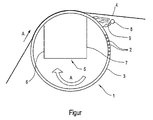
- a suction roll 1 has one with continuous (here only in places indicated) perforations 2 equipped, rotating roller jacket 3.
- a paper web 4 runs over the jacket 3 in the direction of an arrow A.
- a stationary suction box 5 is arranged, which Inner surface of the roll shell 3 touched by sealing strips 6 and 7.
- the sealing strips 6, 7 are each part of sealing devices as they are are known. For this purpose, reference is made, for example, to DE 198 42 837 A1.
- a blow roller with an inside according to Art of the suction box arranged blow box can also be used pipes How the pipe 8 can be placed in front of and / or behind the blow box to hold a fluid bring in or suction.
- a fluid in particular Air, either extracted or blown in, to produce noise effects such as those at the Production of a fibrous web arise.
- a plurality individual suction or blowing devices are provided, in particular individual pipes with openings or holes, the openings are each in Point towards the sealing device.
- the suction and / or extend Blowing devices in particular a suction pipe or a blowing pipe only via one Part of the roller.
- the invention can be used both in the former and in the Press section and / or in the dryer section of a machine for processing a Insert fibrous web.
Landscapes
- Paper (AREA)
Abstract
Description
Claims (4)
- Saug- oder Blaseinrichtung (5) mit einer an eine bewegte, Perforationen (2) aufweisende Materialfläche, insbesondere an den Mantel (3) einer Saug- oder Blaswalze (1), angrenzenden Unterdruck- oder Überdruckzone, insbesondere in einer Maschine zur Herstellung einer Papier-, Karton-, Tissue- oder einer anderen Faserstoffbahn (4), wobei die Unterdruck- oder Überdruckzone mit wenigstens einer Dichtungseinrichtung, die an die bewegte Materialfläche angrenzt, ausgestattet ist, wobei die Dichtungseinrichtung eine mit der bewegten Fläche zusammenwirkende erste auflaufseitige und zweite ablaufseitige Dichtleiste (6, 7) aufweist, dadurch gekennzeichnet, dass in der Umgebung der Unterdruckzone bzw. der Überdruckzone eine Einrichtung zum Einbringen eines Fluids bzw. zum Absaugen eines Fluids angeordnet ist.
- Saug- oder Blaseinrichtung (5) nach Anspruch 1, dadurch gekennzeichnet, dass
die Einrichtung an die auflaufseitige oder ablaufseitige Dichtleiste (6, 7) angrenzt oder in deren Nähe angebracht ist. - Saug- oder Blaseinrichtung (5) nach Anspruch 2, dadurch gekennzeichnet, dass
sich die Einrichtung über die gesamte Breite der Saug- oder Blaseinrichtung (5) erstreckt. - Saug- oder Blaseinrichtung (5) nach einem der vorhergehenden Ansprüche, dadurch gekennzeichnet, dass
zwischen einem von der Mantelfläche (3) der Saug- oder Blaswalze (1) ablaufenden Filz, Sieb oder einer Papier-, Karton-, Tissue- oder einer anderen Faserstoffbahn (4) und der Mantelfläche (3) der Saug- oder Blaswalze (1) ein in Richtung der Längsachse der Saug- oder Blaswalze (1) verlaufendes Rohr (8) angeordnet ist, aus dem ein Fluid in Richtung zu der ablaufseitigen Dichtleiste (7) einbringbar oder aus der Richtung der ablaufseitigen Dichtleiste absaugbar ist.
Applications Claiming Priority (2)
| Application Number | Priority Date | Filing Date | Title |
|---|---|---|---|
| DE2003125687 DE10325687A1 (de) | 2003-06-06 | 2003-06-06 | Dichtungseinrichtung für eine Papiermaschine |
| DE10325687 | 2003-06-06 |
Publications (1)
| Publication Number | Publication Date |
|---|---|
| EP1489228A1 true EP1489228A1 (de) | 2004-12-22 |
Family
ID=33394805
Family Applications (1)
| Application Number | Title | Priority Date | Filing Date |
|---|---|---|---|
| EP04101905A Withdrawn EP1489228A1 (de) | 2003-06-06 | 2004-05-04 | Dichtungseinrichtung für eine Papiermaschine |
Country Status (2)
| Country | Link |
|---|---|
| EP (1) | EP1489228A1 (de) |
| DE (1) | DE10325687A1 (de) |
Citations (5)
| Publication number | Priority date | Publication date | Assignee | Title |
|---|---|---|---|---|
| DE1005825B (de) * | 1954-02-04 | 1957-04-04 | Bowaters Dev And Res Ltd | Saugvorrichtung |
| US3098788A (en) * | 1961-04-18 | 1963-07-23 | Beloit Iron Works | Liquid removal means for rotatable perforated shells |
| US3300374A (en) * | 1965-09-08 | 1967-01-24 | Bird Machine Co | Suction roll with lubricating and washing showers |
| WO1999051812A1 (en) * | 1998-04-02 | 1999-10-14 | Valmet Corporation | Seal construction for a suction box in a suction roll |
| US20010010260A1 (en) * | 2000-01-28 | 2001-08-02 | Voith Paper Patent Gmbh | Machine and process for producing a tissue web |
Family Cites Families (3)
| Publication number | Priority date | Publication date | Assignee | Title |
|---|---|---|---|---|
| US2107812A (en) * | 1935-04-25 | 1938-02-08 | Beloit Iron Works | Suction roll |
| DE29506620U1 (de) * | 1995-04-19 | 1995-06-08 | Voith Sulzer Papiermaschinen GmbH, 89522 Heidenheim | Saugwalze |
| DE10110946A1 (de) * | 2001-03-07 | 2002-09-12 | Voith Paper Patent Gmbh | Dichtungseinrichtung |
-
2003
- 2003-06-06 DE DE2003125687 patent/DE10325687A1/de not_active Withdrawn
-
2004
- 2004-05-04 EP EP04101905A patent/EP1489228A1/de not_active Withdrawn
Patent Citations (5)
| Publication number | Priority date | Publication date | Assignee | Title |
|---|---|---|---|---|
| DE1005825B (de) * | 1954-02-04 | 1957-04-04 | Bowaters Dev And Res Ltd | Saugvorrichtung |
| US3098788A (en) * | 1961-04-18 | 1963-07-23 | Beloit Iron Works | Liquid removal means for rotatable perforated shells |
| US3300374A (en) * | 1965-09-08 | 1967-01-24 | Bird Machine Co | Suction roll with lubricating and washing showers |
| WO1999051812A1 (en) * | 1998-04-02 | 1999-10-14 | Valmet Corporation | Seal construction for a suction box in a suction roll |
| US20010010260A1 (en) * | 2000-01-28 | 2001-08-02 | Voith Paper Patent Gmbh | Machine and process for producing a tissue web |
Also Published As
| Publication number | Publication date |
|---|---|
| DE10325687A1 (de) | 2004-12-23 |
Similar Documents
| Publication | Publication Date | Title |
|---|---|---|
| DE60020238T2 (de) | Verfahren und vorrichtung in der trockenpartieeiner papiermaschine oder dergleichen | |
| DE68921355T2 (de) | Verfahren und Vorrichtung in der Trockenpartie mit einzigem Trockentuch einer Papiermaschine und eine Walze zur Anwendung des Verfahrens. | |
| EP2885456A1 (de) | Dichtleiste | |
| DE2741144A1 (de) | Verfahren fuer das aufbringen eines unterdrucks auf einen filz, ein sieb oder eine fasersuspensionsschicht einer papiermaschine und eine vorrichtung zur durchfuehrung des verfahrens | |
| DE69115020T2 (de) | Vorrichtung zum entfernen von flüssigkeit aus dem innern eines rotierenden zylinders oder einer walze. | |
| DE19633958A1 (de) | Saugpreßwalze | |
| EP1852551B1 (de) | Entwässerungsvorrichtung | |
| EP1050621A2 (de) | Vorrichtung zur Behandlung einer Materialbahn | |
| EP0640716A2 (de) | Anordnung zum Führen einer zu trocknenden Faserstoff-Bahn | |
| DE1461160A1 (de) | Verfahren und Anordnung zur Entfernung von Fluessigkeit aus fluessigkeitshaltigem Material | |
| DE10325687A1 (de) | Dichtungseinrichtung für eine Papiermaschine | |
| EP1673505B1 (de) | Saug- oder blaswalze | |
| EP2391769B1 (de) | Vorrichtung zur herstellung einer materialbahn | |
| AT506408B1 (de) | Vorrichtung und verfahren zur überführung einer materialbahn | |
| EP1795649B1 (de) | Papiermaschinenwalze | |
| EP4077804B1 (de) | Vorrichtung und verfahren zum überführen einer faserstoffbahn | |
| DE102014215192A1 (de) | Entwässerungseinrichtung zur Entwässerung einer Faserstoffbahn, Verfahren zur Entwässerung einer Faserstoffbahn sowie Maschine zur Herstellung einer Faserstoffbahn | |
| EP1496152A1 (de) | Presswalze oder Walzenmantel | |
| DE19728824A1 (de) | Saugwalze für eine Papiermaschine | |
| EP2847381A1 (de) | Dichtleiste mit integriertem schmierwasserzuführungssystem | |
| EP1780332A1 (de) | Vorrichtung und Verfahren zum Behandeln einer Faserstoffbahn, insbesondere einer Karton- oder Papierbahn | |
| DE29623039U1 (de) | Saugpreßwalze | |
| DE10328202A1 (de) | Pressenpartie | |
| DE102006009883A1 (de) | Saugwalze | |
| EP1536061A1 (de) | Saug- oder Blaswalze |
Legal Events
| Date | Code | Title | Description |
|---|---|---|---|
| PUAI | Public reference made under article 153(3) epc to a published international application that has entered the european phase |
Free format text: ORIGINAL CODE: 0009012 |
|
| AK | Designated contracting states |
Kind code of ref document: A1 Designated state(s): AT BE BG CH CY CZ DE DK EE ES FI FR GB GR HU IE IT LI LU MC NL PL PT RO SE SI SK TR |
|
| AX | Request for extension of the european patent |
Extension state: AL HR LT LV MK |
|
| RIN1 | Information on inventor provided before grant (corrected) |
Inventor name: GUTLEDERER, ERWIN Inventor name: HEITZINGER, MICHAEL Inventor name: LUGER, ANTON Inventor name: KEINBERGER, RUEDIGER Inventor name: WULZ, KLAUS Inventor name: KLARER, CHRISTOPH Inventor name: KERSCHBAUMER, JOSEF Inventor name: GRAF-MUELLER, HARALD, DR. Inventor name: SCHREFL, HERBERT |
|
| 17P | Request for examination filed |
Effective date: 20050622 |
|
| AKX | Designation fees paid |
Designated state(s): AT BE BG CH CY CZ DE DK EE ES FI FR GB GR HU IE IT LI LU MC NL PL PT RO SE SI SK TR |
|
| RAP1 | Party data changed (applicant data changed or rights of an application transferred) |
Owner name: VOITH PATENT GMBH |
|
| STAA | Information on the status of an ep patent application or granted ep patent |
Free format text: STATUS: THE APPLICATION IS DEEMED TO BE WITHDRAWN |
|
| 18D | Application deemed to be withdrawn |
Effective date: 20071201 |