EP1486802A1 - Elément texturé pour la conversion du chemin optique et dispositif de rétroéclairage d'écran l'incorporant - Google Patents
Elément texturé pour la conversion du chemin optique et dispositif de rétroéclairage d'écran l'incorporant Download PDFInfo
- Publication number
- EP1486802A1 EP1486802A1 EP04013493A EP04013493A EP1486802A1 EP 1486802 A1 EP1486802 A1 EP 1486802A1 EP 04013493 A EP04013493 A EP 04013493A EP 04013493 A EP04013493 A EP 04013493A EP 1486802 A1 EP1486802 A1 EP 1486802A1
- Authority
- EP
- European Patent Office
- Prior art keywords
- angle
- area light
- light
- prism sheet
- pyramids
- Prior art date
- Legal status (The legal status is an assumption and is not a legal conclusion. Google has not performed a legal analysis and makes no representation as to the accuracy of the status listed.)
- Ceased
Links
- 230000003287 optical effect Effects 0.000 title claims abstract description 135
- 230000004907 flux Effects 0.000 claims description 7
- 238000011156 evaluation Methods 0.000 description 45
- 238000004088 simulation Methods 0.000 description 32
- 230000004048 modification Effects 0.000 description 25
- 238000012986 modification Methods 0.000 description 25
- 239000000463 material Substances 0.000 description 14
- 238000009792 diffusion process Methods 0.000 description 10
- 238000013461 design Methods 0.000 description 9
- 230000007246 mechanism Effects 0.000 description 7
- 239000000758 substrate Substances 0.000 description 6
- 238000005259 measurement Methods 0.000 description 5
- 238000000034 method Methods 0.000 description 5
- 238000010586 diagram Methods 0.000 description 4
- 238000000605 extraction Methods 0.000 description 4
- 239000011521 glass Substances 0.000 description 4
- 238000013041 optical simulation Methods 0.000 description 4
- 230000008569 process Effects 0.000 description 4
- 230000002349 favourable effect Effects 0.000 description 3
- 239000012044 organic layer Substances 0.000 description 3
- 238000010030 laminating Methods 0.000 description 2
- 239000004973 liquid crystal related substance Substances 0.000 description 2
- 239000011347 resin Substances 0.000 description 2
- 229920005989 resin Polymers 0.000 description 2
- VQGHOUODWALEFC-UHFFFAOYSA-N 2-phenylpyridine Chemical compound C1=CC=CC=C1C1=CC=CC=N1 VQGHOUODWALEFC-UHFFFAOYSA-N 0.000 description 1
- NCGICGYLBXGBGN-UHFFFAOYSA-N 3-morpholin-4-yl-1-oxa-3-azonia-2-azanidacyclopent-3-en-5-imine;hydrochloride Chemical compound Cl.[N-]1OC(=N)C=[N+]1N1CCOCC1 NCGICGYLBXGBGN-UHFFFAOYSA-N 0.000 description 1
- 239000004925 Acrylic resin Substances 0.000 description 1
- 229920000178 Acrylic resin Polymers 0.000 description 1
- 238000000342 Monte Carlo simulation Methods 0.000 description 1
- 239000004793 Polystyrene Substances 0.000 description 1
- 238000004364 calculation method Methods 0.000 description 1
- CETPSERCERDGAM-UHFFFAOYSA-N ceric oxide Chemical compound O=[Ce]=O CETPSERCERDGAM-UHFFFAOYSA-N 0.000 description 1
- 239000011248 coating agent Substances 0.000 description 1
- 238000000576 coating method Methods 0.000 description 1
- 230000003247 decreasing effect Effects 0.000 description 1
- 230000000694 effects Effects 0.000 description 1
- 230000005283 ground state Effects 0.000 description 1
- 239000010410 layer Substances 0.000 description 1
- 238000004519 manufacturing process Methods 0.000 description 1
- 238000000059 patterning Methods 0.000 description 1
- 229920003229 poly(methyl methacrylate) Polymers 0.000 description 1
- 239000004417 polycarbonate Substances 0.000 description 1
- 229920000515 polycarbonate Polymers 0.000 description 1
- -1 polyethylene terephthalate Polymers 0.000 description 1
- 229920000139 polyethylene terephthalate Polymers 0.000 description 1
- 239000005020 polyethylene terephthalate Substances 0.000 description 1
- 239000004926 polymethyl methacrylate Substances 0.000 description 1
- 229920002223 polystyrene Polymers 0.000 description 1
- 239000004800 polyvinyl chloride Substances 0.000 description 1
- 229920000915 polyvinyl chloride Polymers 0.000 description 1
- 230000006798 recombination Effects 0.000 description 1
- 238000005215 recombination Methods 0.000 description 1
- 230000003252 repetitive effect Effects 0.000 description 1
- TVIVIEFSHFOWTE-UHFFFAOYSA-K tri(quinolin-8-yloxy)alumane Chemical compound [Al+3].C1=CN=C2C([O-])=CC=CC2=C1.C1=CN=C2C([O-])=CC=CC2=C1.C1=CN=C2C([O-])=CC=CC2=C1 TVIVIEFSHFOWTE-UHFFFAOYSA-K 0.000 description 1
Images


Classifications
-
- G—PHYSICS
- G02—OPTICS
- G02B—OPTICAL ELEMENTS, SYSTEMS OR APPARATUS
- G02B6/00—Light guides; Structural details of arrangements comprising light guides and other optical elements, e.g. couplings
- G02B6/0001—Light guides; Structural details of arrangements comprising light guides and other optical elements, e.g. couplings specially adapted for lighting devices or systems
- G02B6/0011—Light guides; Structural details of arrangements comprising light guides and other optical elements, e.g. couplings specially adapted for lighting devices or systems the light guides being planar or of plate-like form
- G02B6/0033—Means for improving the coupling-out of light from the light guide
- G02B6/005—Means for improving the coupling-out of light from the light guide provided by one optical element, or plurality thereof, placed on the light output side of the light guide
- G02B6/0053—Prismatic sheet or layer; Brightness enhancement element, sheet or layer
-
- G—PHYSICS
- G02—OPTICS
- G02F—OPTICAL DEVICES OR ARRANGEMENTS FOR THE CONTROL OF LIGHT BY MODIFICATION OF THE OPTICAL PROPERTIES OF THE MEDIA OF THE ELEMENTS INVOLVED THEREIN; NON-LINEAR OPTICS; FREQUENCY-CHANGING OF LIGHT; OPTICAL LOGIC ELEMENTS; OPTICAL ANALOGUE/DIGITAL CONVERTERS
- G02F1/00—Devices or arrangements for the control of the intensity, colour, phase, polarisation or direction of light arriving from an independent light source, e.g. switching, gating or modulating; Non-linear optics
- G02F1/01—Devices or arrangements for the control of the intensity, colour, phase, polarisation or direction of light arriving from an independent light source, e.g. switching, gating or modulating; Non-linear optics for the control of the intensity, phase, polarisation or colour
- G02F1/13—Devices or arrangements for the control of the intensity, colour, phase, polarisation or direction of light arriving from an independent light source, e.g. switching, gating or modulating; Non-linear optics for the control of the intensity, phase, polarisation or colour based on liquid crystals, e.g. single liquid crystal display cells
- G02F1/133—Constructional arrangements; Operation of liquid crystal cells; Circuit arrangements
- G02F1/1333—Constructional arrangements; Manufacturing methods
- G02F1/1335—Structural association of cells with optical devices, e.g. polarisers or reflectors
-
- G—PHYSICS
- G02—OPTICS
- G02B—OPTICAL ELEMENTS, SYSTEMS OR APPARATUS
- G02B5/00—Optical elements other than lenses
- G02B5/04—Prisms
- G02B5/045—Prism arrays
-
- G—PHYSICS
- G02—OPTICS
- G02F—OPTICAL DEVICES OR ARRANGEMENTS FOR THE CONTROL OF LIGHT BY MODIFICATION OF THE OPTICAL PROPERTIES OF THE MEDIA OF THE ELEMENTS INVOLVED THEREIN; NON-LINEAR OPTICS; FREQUENCY-CHANGING OF LIGHT; OPTICAL LOGIC ELEMENTS; OPTICAL ANALOGUE/DIGITAL CONVERTERS
- G02F1/00—Devices or arrangements for the control of the intensity, colour, phase, polarisation or direction of light arriving from an independent light source, e.g. switching, gating or modulating; Non-linear optics
- G02F1/01—Devices or arrangements for the control of the intensity, colour, phase, polarisation or direction of light arriving from an independent light source, e.g. switching, gating or modulating; Non-linear optics for the control of the intensity, phase, polarisation or colour
- G02F1/13—Devices or arrangements for the control of the intensity, colour, phase, polarisation or direction of light arriving from an independent light source, e.g. switching, gating or modulating; Non-linear optics for the control of the intensity, phase, polarisation or colour based on liquid crystals, e.g. single liquid crystal display cells
- G02F1/133—Constructional arrangements; Operation of liquid crystal cells; Circuit arrangements
- G02F1/1333—Constructional arrangements; Manufacturing methods
- G02F1/1335—Structural association of cells with optical devices, e.g. polarisers or reflectors
- G02F1/1336—Illuminating devices
- G02F1/133602—Direct backlight
- G02F1/133606—Direct backlight including a specially adapted diffusing, scattering or light controlling members
- G02F1/133607—Direct backlight including a specially adapted diffusing, scattering or light controlling members the light controlling member including light directing or refracting elements, e.g. prisms or lenses
-
- H—ELECTRICITY
- H10—SEMICONDUCTOR DEVICES; ELECTRIC SOLID-STATE DEVICES NOT OTHERWISE PROVIDED FOR
- H10K—ORGANIC ELECTRIC SOLID-STATE DEVICES
- H10K50/00—Organic light-emitting devices
- H10K50/80—Constructional details
- H10K50/85—Arrangements for extracting light from the devices
-
- H—ELECTRICITY
- H10—SEMICONDUCTOR DEVICES; ELECTRIC SOLID-STATE DEVICES NOT OTHERWISE PROVIDED FOR
- H10K—ORGANIC ELECTRIC SOLID-STATE DEVICES
- H10K59/00—Integrated devices, or assemblies of multiple devices, comprising at least one organic light-emitting element covered by group H10K50/00
- H10K59/80—Constructional details
- H10K59/875—Arrangements for extracting light from the devices
- H10K59/879—Arrangements for extracting light from the devices comprising refractive means, e.g. lenses
Definitions
- the present invention relates to an optical device that converts the advancing direction of light emitted by an area light emitting device, an area light apparatus that includes the optical device and the area light emitting device, and a display that uses the area light apparatus as a backlight.
- Japanese Laid-Open Patent Publication No. 4-67016 discloses a light apparatus 1000 shown in Fig. 17.
- the light apparatus 1000 includes a light source 100, which is a fluorescent tube, a reflector box 200 the inner surface of which is specular or white, an opaline diffusion plate 300, a transparent prism sheet 400 functioning as an optical device, and a transmissive display panel 500.
- the prism sheet 400 has on a side triangle pole shaped prisms arranged parallel to one another.
- Light emitted from the light source 100 either directly reaches the diffusion plate 300 or reaches the diffusion plate 300 after being reflected by the inner surfaces of the reflector box 200.
- the light is then converted into a uniform area light by the diffusion plate 300.
- components of the light that are diffused in the vertical direction are gathered by the prism sheet 400 in a direction of the normal to the display surface of the display panel 500, and reach the display panel 500. Therefore, compared to a case where no prism sheet 400 is provided, a greater amount of light reaches the display panel in a frontward direction, which permits an image having a high brightness to be displayed.
- a display 1010 shown in Fig. 18 has, in addition to the configuration of the light apparatus 1000 of Fig. 17, another prism sheet 400a located between the prism sheet 400 and the diffusion plate 300.
- the prisms on the prism sheet 400a extend in a direction orthogonal to the prisms on the prism sheet 400.
- light components in one direction left-right direction as viewed in the drawing
- light components in a direction perpendicular to the left-and-right direction up-down direction as viewed in the drawing
- the components of light produced by the light source 100 are two-dimensionally gathered and reach the display panel 500. Accordingly, compared to the light apparatus 1000 shown in Fig. 17, a greater amount of light is gathered in a specific direction (a direction of the normal to the display panel 500), which further increases the brightness of the display.
- the display 1010 of Fig. 18 requires the two prism sheets 400, 400a, the display 1010 has a greater thickness a greater number of components than the light apparatus 1000 of Fig. 17. This makes the design and production difficult.
- Japanese Laid-Open Patent Publication No. 6-308485 discloses a display 1020 having a single prism sheet 401 as shown in Fig. 19.
- the prism sheet 401 two-dimensionally gathers light.
- the display 1020 includes the light source 100, the reflector box 200, the diffusion plate 300, the display panel 500, and the prism sheet 401.
- the prism sheet 401 is located between the diffusion plate 300 and the display panel 500.
- square pyramid shaped prisms are arranged in a grid pattern.
- Fig. 20 is a partial front view showing the prism sheet 401 of Fig. 19.
- Figs. 20a and 20b are cross-sectional views of the prism sheet 401 taken along lines 20a-20a and 20b-20b, respectively.
- Fig. 21 shows the path of light in the prism sheet 401 in Fig. 20a.
- each of slopes 401b forming the pyramids is designed to be inclined by an angle ⁇ 5 (prism angle ⁇ 5) with respect to a plane parallel to a plane 401a, which is an incident surface, based on Snell laws of refraction represented by the following equations (formula 1).
- ⁇ 2 sin -1 (sin ⁇ 1/n1) (n1 is the index of refraction of the prism sheet)
- ⁇ 3 ⁇ 5 - ⁇ 2
- the ray L1 is refracted at the interface between the air and the plane 401a at an angle ⁇ 2, then advances through the prism sheet 401.
- the ray L1 reaches a prism plane 401b at an angle ⁇ 3 with respect to the normal S2 to the prism plane 401b, and is refracted at an angle ⁇ 4 with respect to a line S3 that is parallel to the normal S1 to the plane 401a.
- the light L1 then exits into the air.
- the angle of the slope 401b is computed by substituting these values into the formula 1. As shown in Fig. 22, the angle of the slope 401b is 25° with respect to the normal S1 to the plane 401a.
- the angle of the slope 401b with respect to the normal S1 to the plane 401a are set as shown below.
- the angle of the slope 401b is set to 17°.
- the angle of the slope 401b is set to 20.5°.
- the angle of the slope 401b is set to 32°.
- the angle of the slope 401b is set to 34°.
- the angle of the slope 401b is set to 37.5°.
- materials for optical devices such as prism sheets are typically selected in terms of transparency, workability, and weight.
- members formed by coating these materials may be employed.
- the index of refraction of applicable material is in a range between 1.40 and 1.70, inclusive.
- the angle of each of the slopes forming the pyramids (projections) with respect to the normal to an incident surface is in a range between 17° and 37.5°, inclusive.
- the inventors of the present invention performed simulations using an organic electroluminescent device having an isotropic light emission property and a reflection property as a light source, and found out that, if a prism sheet is formed according to a design using the above formula 1, the brightness cannot be sufficiently increased. The reason for this is considered that some of light that enters the prism sheet was reflected in the prism sheet toward the light source and reached the light source, and this portion of light was reflected by the reflector plate of the light source toward the prism sheet and re-entered the prism sheet.
- a first objective of the present invention is to provide an optical device that has an improved optical properties compared to conventional optical devices.
- a second objective of the present invention is to provide an optical device that is different from the optical device shown in the prior art section and has the same or superior characteristics as that of the prior art optical devices.
- a third objective of the present invention is to provide a light apparatus having such an optical device.
- a forth objective of the present invention is to provide a display having such a light apparatus as a backlight.
- the present invention provides an optical device for changing an optical path of light that reaches the device.
- the optical device is transparent.
- the optical device has an incident surface and a light exit surface located at an opposite side from the incident surface.
- the light exit surface defines a plurality of projections and/or recesses.
- the projections project away from the incident surface.
- the recesses are dented toward the incident surface.
- Sections of the light exit surface that define projections and/or recesses include side faces of pyramids or truncated pyramids.
- Each of the pyramids and the truncated pyramids has a bottom that is an imaginary plane substantially parallel to the incident surface.
- the side faces of each of the pyramids and the truncated pyramids are slopes. At least one of the slopes is inclined at a predetermined angle relative to the normal to the incident surface.
- the predetermined angle is in a range greater than 17° and less than 60°.
- slopes refer to slopes of a pyramid and do not include the bottom of the pyramid. Each slope is triangular.
- the present invention also provides an optical device for changing an optical path of light that reaches the device.
- the optical device is transparent.
- the optical device has an incident surface and a light exit surface located at an opposite side from the incident surface.
- the light exit surface defines a plurality of projections and/or recesses.
- the projections project away from the incident surface.
- the recesses are dented toward the incident surface.
- Sections of the light exit surface that define projections and/or recesses include side faces of cones or truncated cones.
- Each of the cones and the truncated cones has a bottom that is an imaginary plane substantially parallel to the incident surface.
- the side face of each cone or each truncated cone is inclined at a predetermined angle relative to the normal to the incident surface.
- the predetermined angle is in a range greater than 30° and less than 55°.
- the side surface of a cone refers to the surface of the cone except for the bottom.
- the first area light apparatus 101 includes an optical device, which is a prism sheet 1, and an area light-emitting device, which is an organic electroluminescent device (organic EL device) 2.
- an optical device which is a prism sheet 1
- an area light-emitting device which is an organic electroluminescent device (organic EL device) 2.
- the organic EL device 2 has a transparent substrate and is formed by consecutively laminating a transparent electrode 22, an organic layer 23, and a reflecting electrode 24 on the transparent substrate 21.
- the transparent substrate 21 is formed, for example, of glass or an acrylic resin.
- the transparent electrode 22 is formed, for example, of ITO.
- the organic layer 23 contains organic light-emitting material such as Alq3 and Ir(ppy)3.
- the reflecting electrode 24 is formed, for example, of Al.
- the organic EL device 2 has an isotropic light emission property. That is, light generated at the organic light-emitting material is directed to all the directions.
- the reflecting electrode 24 reflects light directed from the organic layer 23 to the reflecting electrode 24 and light that has been reflected by the prism sheet 1 and reaches the organic EL device 2 toward the prism sheet 1.
- the reflecting electrode 24 provides the organic EL device 2 with a reflection property.
- the prism sheet 1 has an incident surface 11 and a light exit surface 12 located at an opposite side from the incident surface 11.
- the organic EL device 2 has the light extracting surface 25, which is a surface of the transparent substrate 21 that faces the incident surface 11.
- the light extracting surface 25 and the incident surface 11 are arranged to be parallel to each other.
- isotropic light emission property refers to a property in which the brightness in the same direction with respect to the normal to a light extracting surface of an area light-emitting device is substantially uniform.
- the reflection property refers to a property in which light from an optical device is reflected back to the optical device.
- the isotropic light emission property of the organic EL element 2 is preferably designed such that the number of luminous fluxes in a range between 30° and 60°, inclusive, more preferably, in a range between 40° and 50°, inclusive, and most preferably, in a range about 45° with respect to the normal to a light extracting surface 25 is the greatest compared to the amount of light in other directions.
- Such a device is formed by properly designing and selecting the shape of the substrate, thickness of each layer, and the materials of the organic EL element 2.
- the light exit surface 12 of the prism sheet 1 defines square pyramid shaped projections 13, which project away from the incident surface 11.
- a section of the light exit surface 12 that defines each projection 13 includes side faces of the corresponding pyramid.
- the bottom of each pyramid has a bottom 13a, which is an imaginary plane substantially parallel to the incident plane 11.
- the side faces are formed with slopes 13b.
- the bottom 13a of each projection 13 is substantially square, and is located in an imaginary plane that lies substantially parallel to the incident surface 11.
- the slopes 13b of each projection 13 form part of the light exit surface 12.
- the imaginary plane contains the points and sides forming the bottom of each projection 13.
- the prism sheet 1 may be configured such that an imaginary plane that contains the bottom of at least one of the projections 13 may be displaced from the imaginary plane that contains the bottoms of the other projections 13.
- the inventors of the present invention performed ray tracking simulations by Monte Carlo method. Through the simulations, the inventors computed changes of front brightness of the first area light apparatus (the brightness in a direction of the normal to the incident surface 11) when the angle of slopes 13b of the projections 13 were varied. The conditions of the simulations are shown below.
- the angle defined by the normal and each slope 13b refers to the smallest angle in the angles defined by the normal and lines on the slope 13b.
- the angle defined by the normal and each slope 13b refers to an angle defined by the normal to the incident surface 11 and a line in the slope 13b that includes the peak of the slope 13b, or the peak of the corresponding pyramid, and perpendicularly intersects the corresponding bottom 13a.
- the organic EL device 2 and the prism sheet 1 are square plates each side of which is 5 cm long.
- the distance between the light extracting surface 25 and the incident surface 11 is 10 ⁇ m.
- the distance between the light extracting surface 25 and the reflecting electrode 24 is 500 ⁇ m.
- a square plane that is away from the peak of each projection 13 by 10 ⁇ m and parallel to the light extracting surface 25 is set as a measurement plane.
- the sides of the measurement plane is 5 cm long each.
- the shape of the measurement plane and the shape of the prism sheet 1 match the shape of the light extracting surface 25.
- the measurement plane has one million rays.
- the projections 13 have identical shapes. Each bottom 13a of each projection 13 is 100 ⁇ m long.
- the index of refraction of the prism sheet 1 is 1.50.
- Each bottom 13a is common to the corresponding adjacent pair of projections 13 (pyramids). However, the outer bottom 13a of each outermost projection 13 is not common to any other projections 13.
- an angle defined by each slope 13b of the projections 13 and the normal 11H to the incident surface 11 is referred to as an angle ⁇ .
- Table 1 The results are shown in Table 1.
- the brightness is expressed as a front brightness ratio (brightness ratio) with respect to the brightness in a direction of the normal to the light extracting surface 25 of the organic EL device 2, that is, with respect to the front brightness.
- a first prism sheet 1a shown in Fig. 3 is a modifications of the first prism sheet 1 shown in Fig. 2.
- the first prism sheet 1a has cone shaped projections 14.
- Each projection 14 has a circular bottom 14a the diameter of which is 100 ⁇ m.
- the projections 14 are arranged such that each adjacent pair of the bottoms 14a contact each other.
- the projections 14 are arranged in a hexagonal closest packed structure.
- the other configurations are the same as those of the first area light apparatus shown in Fig. 1.
- an angle defined by each slope 14b of the projections 14 and the normal 11H to the incident surface 11 was varied as shown in Table 2 below, and the brightness in a direction of the normal to the incident surface was simulated.
- the brightness is expressed as the front brightness of the light extracting surface 25 of the organic EL device 2, that is, as a ratio (front brightness ratio) with respect to the front brightness of an area light apparatus that includes only the organic EL device 2.
- the front brightness is expected to be maximized when the angle defined by each slope 13b of the projections 13 and the normal 11H to the incident surface 11 or the angle defined by each slope 14b of the projections 14 and the normal 11H is 25°.
- Tables 1 and 2 regardless whether the projections were shaped as square pyramids or cones, there existed angles at which the front brightness was greater than the case of the slope angle of 25°. That is, the inventors of the present invention found out that at certain angles of slopes of projections, the front brightness is increased to a level that cannot be achieved by conventional optical designs in which reflection property is not taken into consideration. In other words, the inventors found out requirements for prism sheets and area light apparatuses that exert superior optical properties. The evaluations will now be described in more details.
- the front brightness is higher than that in a case of an angle of 25°, where the front brightness is expected to be maximized when a design according to Snell laws without considering the reflection property is applied. That is, when the slope angle was set in any of the following angle ranges, substantially favorable optical properties (the property of changing path of rays and the property for gathering light) were obtained.
- a commercially available prism sheet 10a shown in Fig. 4 was used.
- the prism sheet 10a includes an incident surface 110a and triangle pole shaped prisms 130a arranged parallel to one another.
- simulations were performed for the front brightness of an area light apparatus that uses the prism sheet 10a.
- the front brightness was 1.30.
- the conditions of the simulations are shown below.
- the index of refraction of the prism sheet 10a is 1.60.
- each slope 130a-1 of the triangle pole (prism) with respect to the normal to the incident surface 110a is 45°.
- the angle of 45° is an angle in Table 1 that is defined by the normal to the incident surface and the slope of the pyramids or cones at which angle the front brightness is maximized.
- Fig. 5 shows an area light apparatus of another comparison example.
- the light apparatus of Fig. 5 is formed by stacking two prism sheets 10a, 10b that are the same as the prism sheet shown in Fig. 4 used in Evaluation (2).
- the prism sheets 10a, 10b have triangle pole shaped prisms 130a, 130b, respectively.
- the prism sheets 10a, 10b are stacked such that the prisms 130a, 130b lie perpendicular to each other.
- the front brightness was 1.50.
- the other conditions of the simulation were the same as those in the simulation of the comparison example in Evaluation (2).
- the first area light apparatus of the present embodiment had a greater front brightness than that of the area light apparatus shown in Fig. 5. That is, when the slope angle was set in the following angle ranges, a light gathering property (optical property) superior to that of conventional apparatuses was obtained.
- a prism sheet in which the slopes 13b of the projections 13 satisfied the following requirement (4-1) had a greater front brightness than a prism sheet having the cone shaped projections 14, in which the angle of the slopes 14b with respect to the normal 11H to the incident surface was the same as that of the slopes 13b.
- the prism sheet with the projections 13 had a sufficient optical performance that the front brightness ratio was no less than 1.20.
- the prism sheet 1 and the area light apparatus had a significantly superior performance when the angle ⁇ of the projections 13 was 45° compared to the cases where the angle ⁇ had other values. That is, the front brightness ratio of the prism sheet 1 and the area light apparatus was maximized to 1.69 when the angle ⁇ was 45°.
- the front brightness of the prism sheet 1 and the area light apparatus was no less than 90% of the case where the angle ⁇ was 45°. That is, the prism sheet 1 and the area light apparatus had substantially the same performance as the case where the angle ⁇ was 45°.
- the first area light apparatus 101 and the prism sheet 1 shown in Fig. 1 can be formed by a conventional process.
- the organic EL device 2 can be formed by a film forming process used for forming conventional organic EL device. That is, the organic EL device 2 is formed by properly laminating materials used in conventional organic EL device.
- the first prism sheet 1 can be formed by pouring a material such as glass or resin into a mold in which pyramids are carved and solidifying the material.
- the first prism sheet 1 can also be formed by a conventional patterning process in which patterns are formed on a glass or resin material. Further, the first prism sheet 1 can be formed by carving the projections 13 on a transparent plate.
- the organic EL device 2 and the first prism sheet 1 can be attached to each other by conventional assembling process or assembling members for area light apparatuses.
- the first prism sheet 1 has the square pyramids having slopes in one of the above described angle ranges on a side opposite from the incident surface 11.
- the square pyramids densely and entirely cover the surface. Therefore, the brightness in a specific direction is significantly increased.
- the paths of light generated by an area light-emitting device that has an isotropic light-emitting property and a reflection property are effectively converted into a specific direction (in this specification, the front direction). That is, in this embodiment, unlike the conventional prism sheets 10a, 10b, 400, 400a, 401 shown in Figs. 4, 5, and 17 to 22, which are formed without considering the reflection property, highly improved optical properties such as the light gathering property are obtained.
- the first area light apparatus 101 having the first prism sheet 1 has a higher brightness in a specific direction, for example, in a direction of the normal to the incident surface 11 (the front direction) than an area light apparatus having a prism sheet that is designed without considering the reflection property.
- the front brightness ratio was higher than that of a prism sheet and an area light apparatus that were designed to have the angle ⁇ of 17° without taking the reflection property into consideration.
- the front brightness was higher than 1.30, which was the front brightness ratio of the area light apparatus of Evaluation (2), which used a commercially available prism sheet.
- the prism sheet and the area light apparatus had a significantly superior performance when the angle ⁇ was 45° compared to the cases where the angle ⁇ had other values. That is, the front brightness ratio of the prism sheet and the area light apparatus was 1.44 when the angle ⁇ was 45°.
- the front brightness of the prism sheet 1 and the area light apparatus was no less than 90% of the case where the angle ⁇ was 45°. That is, the prism sheet 1 and the area light apparatus had substantially the same performance as the case where the angle ⁇ was 45°.
- the prism sheet 1 and the area light apparatus had a performance in which the front brightness ratio was no less than 80% of that of the case where the angle ⁇ was 45°. Also, when the angle ⁇ was more than 47.5° and less than 60°, the prism sheet 1 and the area light apparatus had a performance in which the front brightness ratio was no less than 70% of that of the case where the angle ⁇ was 45°.
- the front brightness ratio was higher than or equal to that of a prism sheet and an area light apparatus having the angle ⁇ of 20.5°.
- the front brightness was higher than or equal to 1.30, which is the front brightness ratio of the area light apparatus of Evaluation (2), which used a commercially available prism sheet.
- the front brightness was higher than or equal to 1.50, which is the front brightness ratio of the area light apparatus of Evaluation (3), which used two commercially available prism sheets.
- the prism sheet and the area light apparatus had a significantly superior performance when the angle ⁇ was 45° compared to the cases where the angle ⁇ had other values. That is, the front brightness ratio of the prism sheet and the area light apparatus was 1.62 when the angle ⁇ was 45°.
- the angle ⁇ satisfied the following requirement (13-1) or preferably the requirement (13-2), the front brightness of the prism sheet 1 and the area light apparatus was no less than 90% of the case where the angle ⁇ was 45°. That is, the prism sheet 1 and the area light apparatus had substantially the same performance as the case where the angle ⁇ was 45°.
- the front brightness ratio was higher than that of a prism sheet and an area light apparatus that were designed to have the angle ⁇ of 34° without taking into reflection property into consideration.
- the front brightness was higher than or equal to 1.30, which is the front brightness ratio of the area light apparatus of Evaluation (2), which used a commercially available prism sheet.
- the front brightness was higher than or equal to 1.50, which is the front brightness ratio of the area light apparatus of Evaluation (3) having two commercially available prism sheets.
- the prism sheet and the area light apparatus had a significantly superior performance when the angle ⁇ is 45° compared to the cases where the angle ⁇ had other values. That is, the front brightness ratio of the prism sheet and the area light apparatus was 1.72 when the angle ⁇ was 45°.
- the front brightness of the prism sheet 1 and the area light apparatus was no less than 90% of the case where the angle ⁇ was 45°. That is, the prism sheet 1 and the area light apparatus had substantially the same performance as the case where the angle ⁇ was 45°.
- the prism sheet 1 and the area light apparatus had a performance in which the front brightness ratio was no less than 80% of that of the case where the angle ⁇ was 45°. Also, when the angle ⁇ was more than 47.5° and less than 57.5°, the prism sheet 1 and the area light apparatus had a performance in which the front brightness ratio was no less than 70% of that of the case where the angle ⁇ was 45°.
- the front brightness ratio was higher than that of a prism sheet and an area light apparatus that were designed to have the angle ⁇ of 34° without taking the reflection property into consideration.
- the front brightness was higher than or equal to 1.30, which is the front brightness ratio of the area light apparatus of Evaluation (2) having a commercially available prism sheet.
- the front brightness was higher than or equal to 1.50, which is the front brightness ratio of the area light apparatus of Evaluation (3) having two commercially available prism sheets.
- the prism sheet and the area light apparatus had a significantly superior performance when the angle ⁇ was 45° compared to the cases where the angle ⁇ had other values. That is, the front brightness ratio of the prism sheet and the area light apparatus was 1.68 when the angle ⁇ was 45°.
- the front brightness of the prism sheet 1 and the area light apparatus was no less than 90% of the case where the angle ⁇ was 45°. That is, the prism sheet 1 and the area light apparatus had substantially the same performance as the case where the angle ⁇ was 45°.
- the reason why the area light apparatus of this embodiment has an improved front brightness is the existence of optical paths (light) described in Mechanisms 1 to 4 below.
- the existence of the optical paths was discovered by the inventors of the present invention through repetitive performance of the simulations under the above listed conditions.
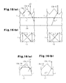
- the projections 13 of the prism sheet 1 are configured that the range of the angle ⁇ is no less than 25° and no more than 45°, some of light that is emitted through one of the projections 13 is subjected to the Fresnel reflection at a slope 13b of an adjacent one of the projections 13 and advances in the front direction as shown in Fig. 13.
- the front brightness is increased.
- the prism sheet 1 emits light of the following properties in the front direction.
- the ray LA is an incident light that reaches a slope 13b-1.
- the ray LA has the same angle of incidence as a ray LB that reaches the slope 13b-2, which is opposite from the slope 13b-1, and refracted to the front direction.
- the ray LA is totally reflected by the slope 13b-1 and emitted to the outside through the slope 13b-2.
- the ray LA then reaches an adjacent projection 13 and is totally reflected by a slope 13b-4 at a side opposite from a slope 13b-3 through which the ray LA enters the projection 13.
- the advancing direction of the ray LA between the projections 13A and 13B in the cross-sectional view of Fig. 14(a) of the above conditions was computed.
- the results showed that the advancing direction of the ray LA is substantially parallel to the incident surface 11. Since the entire prism sheet 1, including the projections 13A, 13B, has a uniform index of refraction, the angle of incidence of the ray LA at the slope 13b-1 and the angle of incidence of the ray LA at the slope 13b-4 are substantially the same. Therefore, a ray LA' reflected by the reflecting electrode 24 is substantially parallel to the ray LA in the cross-sectional view of Fig. 14(a). When reaching the slope 13b-6, which is at the same side as the slope 13b-2 and 13b-4, the ray LA' is emitted in the front direction.
- the ray LA After being emitted through the projection 13A, the ray LA is subjected to the Fresnel reflection at the slope 13b-3 of the projection 13B. Calculations reveals that the ray LA" after the Fresnel reflection also advances in the front direction.
- the prism sheet and the area light apparatus of this embodiment have the highest front brightness when the angle ⁇ is in the vicinity of 45°.
- the prism sheet 1 emits light of the following properties in the front direction.
- a ray LC is an incident light that reaches a slope 13b-7.
- the ray LC has the same angle of incidence as a ray LD that reaches a slope that is opposite from the slope 13b-7 or an adjacent slope 13b (hereinafter denoted as 13b-8), and refracted to the front direction.
- the area light apparatus of this embodiment has a higher front brightness than area light apparatus having a conventional prism sheet.
- the prism sheet the index of refraction of which is 1.64 has an increased front brightness ratio when the angle ⁇ is approximately 52.5°
- the prism sheet the index of refraction of which is 1.40 has an increased front brightness ratio when the angle ⁇ is approximately 51°. The reason for this is considered that these prism sheet satisfy the following requirements.
- the ray LE is an incident light that reaches a slope 13b-10.
- the ray LE advances in a direction parallel to a ray LF that reaches the slope 13b-11, which is opposite from the slope 13b-10, and emitted in the front direction.
- the ray LE is totally reflected by the slope 13b-10 and is reflected by the slope 13b-11 toward the reflecting electrode 24.
- the prism sheet 1 and the area light apparatus of this embodiment have a greater number of optical paths to direct light in the front direction than conventional prism sheets and area light apparatuses. This is considered to have increased the front brightness of the prism sheet 1 and the area light apparatus of this embodiment.
- the prism sheet of this embodiment has a greater number of luminous fluxes advancing along the optical paths described below than conventional prism sheets, and therefore has the above described significantly improved optical properties.
- the ray LD in Fig. 15(a) and the ray LF in Fig. 16(a) are emitted in the front direction after reaching one of the slopes 13b (provisionally denoted as 13b-A).
- the ray LC in Fig. 15(a) advances in a direction parallel to the direction of the rays LD, LF in the prism sheet 1 and reaches one of the slopes 13b (provisionally denoted as 13b-B) that is different from the slope 13b-A.
- the ray LC is reflected by the slope 13b-B and advances in a direction parallel to the incident surface 11.
- the ray LC is then reflected toward the reflecting electrode 24 by another one of the slopes 13b (provisionally denoted as 13b-C) that is different from the slope 13b-B.
- the ray LC is then reflected toward the prism sheet 1 by the reflecting electrode 24.
- the reflected ray LC, or a ray LC' then reaches another slope 13b (provisionally denoted as 13b-D) and is emitted in a path along the front direction from the slope 13b-D.
- the first area light apparatus 101 and the first prism sheet 1 exerted favorable properties even if the reflecting electrode 24 was inclined relative to the light extracting surface 25 (the incident surface 11). Examples will now be described.
- an end (a side) of the reflecting electrode 24 was fixed and the other end was moved.
- the amount of movement is represented by an angle with respect to the position of the reflecting electrode 24 in Example 1, which position is referred to as an inclination angle of 0°.
- Example 6 when the angle ⁇ was 35°, the same optical properties as the case in which the inclination angle was 0° were obtained if the inclination angle was in a range greater than 0° and less than 15°. Also, even when the inclination angle was in a range greater than 0° and no more than 25°, significantly improved optical properties were obtained. Specifically, the front brightness ratio was no less than 83% of a case where the inclination angle is 0°.
- Example 7 when the angle ⁇ was 40°, the same optical properties as the case in which the inclination angle was 0° were obtained if the inclination angle was in a range greater than 0° and less than 15°. Also, even when the inclination angle was in a range greater than 0° and no more than 25°, significantly improved optical properties were obtained. Specifically, the front brightness ratio was no less than 83% of a case where the inclination angle is 0°.
- the inclination angle was in a range greater than 0° and no more than 20° and the angle ⁇ was 43°, significantly improved optical properties were obtained. Specifically, the front brightness ratio was no less than 88% of a case where the inclination angle is 0°.
- the front brightness ratio was no less than 81% of a case where the inclination angle is 0°. Also, even when the inclination angle was in a range greater than 0° and no more than 25°, improved optical properties were obtained. Specifically, the front brightness ratio was no less than 67% of a case where the inclination angle is 0°.
- an area light apparatus in which a plurality of asperities are formed at least on the reflecting electrode 24 has a significantly improved optical properties. Forming asperities increases the amount of light emitted from the organic EL device 2 compared to an organic EL device having no asperities. Also, the prism sheet 1 increases the front brightness.
- the prism sheet 1 may be inclined relative to the reflecting electrode 24.
- the first area light apparatus and the first prism sheet have superior optical properties that cannot be achieved by conventional prism sheets that are designed without taking the reflection property into consideration.
- the projections 13 on the first prism sheet may be pyramids other than square pyramids.
- the reason why the first prism sheet has a significantly increased brightness in a specific direction is that the slopes 13b of the projections are in any of the above described ranges of the angle ⁇ . Therefore, as long as the slopes 13b of the projections 13 are in any of the above described ranges of the angle ⁇ , the shape of the projections 13 may be changed to pyramids other than square pyramids. For example, the same optical properties as described above can be obtained even if the projections 13 are formed as triangular pyramids, equilateral triangular pyramids, rectangular pyramids, hexagonal pyramids, or equilateral hexagonal pyramids.
- the angle of at least one side of each pyramid needs to be in any of the above described ranges.
- the pyramids are designed such that the angles of all the sides of each pyramid are in any of the angle ranges, a prism sheet and an area light apparatus having a significantly improved optical properties are obtained.
- each side of each pyramid can be arranged to be common to an adjacent pyramid.
- the shape of the projections 13 are preferably square pyramids since the number of steps of carving is less than the case of other types of pyramids.
- the first prism sheet 1 has an improved property for changing optical path because the angle the slopes 13b of each pyramid, which is the projection 13, is set to satisfy any of the above described requirements. Therefore, if the projections have slopes the angle of which is in any of the above described angle ranges, an improved prism sheet is obtained. That is, even if the projections are truncated pyramids or even if one or more of the slopes of each pyramid is curved, it is possible to improved optical properties to a level that cannot be achieved by a prism sheet that is designed without taking the reflection property into consideration. That is, it is possible to form a prism sheet and an area light apparatus that have superior optical properties and are different from conventional prism sheet and area light apparatus.
- the optical properties are improved even if the projections of Fig. 6 are replaced by other types of truncated pyramids as long as each of such pyramids has at least one slope in any of the above listed angle ranges.
- the front brightness was higher than that of a prism sheet that has cones the angle of which is 25°, and exerts the maximum front brightness when the reflection property is not taken into consideration. That is, when the projections 14 were formed into cones the slopes of which were in the angle range shown below with respect to the normal 11H to the incident surface, an improved optical properties were obtained.
- the slope of a cone refers to a surface of a cone other than the bottom and corresponds to slopes of a pyramid.
- the optical properties of the prism sheet was superior to those of the area light apparatus shown in Fig. 4, which has a front brightness ratio of 1.30. That is, the prism sheet had better optical properties than conventional prism sheets. Also, the brightness of the area light apparatus in a specific direction was higher than the brightness in other directions.
- the prism sheet and the area light apparatus had sufficient light gathering property and thus had a front brightness that is higher than the front brightness of organic EL devices.
- a prism sheet has superior optical properties as long as the angle ⁇ a is in any of the above listed ranges. Accordingly, it was found out that optical properties that are equal to or better than those of conventional prism sheets and area light apparatus can be obtained, and that a prism sheet and an area light apparatus that are different from conventional ones are obtained.
- the projections are shaped like pyramids, truncate pyramids, cones, or truncated cones as long as each projection has a slope the angle of which is any of the above listed ranges. Therefore, even if a prism sheet is designed such that at least one of the projections has a shape different from the shapes of the other projections, such that the bases of the projections do not contact one another, or such that a side of any projection is not common to any other projection, the prism sheet has the property for changing optical paths as described above.
- the projections on a prism sheet may be shaped as shown in any of Figs. 8, 9, and 10.
- the projections 13 are shaped as square pyramids of different sizes.
- the projections 13 include rectangular pyramids and square pyramids.
- the projections 13 are shaped as square pyramids the sides of which do not contact. It is preferable that all the slopes 13b of the projections 13 on the first prism sheet have an angle in any of the above listed angle ranges relative to the normal 11H to the incident surface 11 so that the prism sheet has significantly superior optical properties.
- the prism sheets in the above embodiment include prism sheets that have projections shaped like pyramids, truncated pyramids, cones, or truncated cones even if the projections only partly cover the surface of the prism sheet and have no slopes the angle of which is in any of the above listed angle ranges.
- Area light-emitting devices other than organic EL devices may be employed as long as the devices has an isotropic light emission property and a reflection property.
- inorganic electroluminescent devices or area light-emitting devices of an optical waveguide type may be used.
- organic EL devices when organic EL devices are used, the type of the devices is not limited to the bottom emission type shown in Fig. 1, but may be a top emission type or a type that emits light from edges of a transparent substrate.
- the wavelength of emitted light may be changed as necessary.
- the prism sheets of the above embodiment do not need to be used in the area light-emitting devices having the above described light emitting properties, but may be used in area light-emitting devices having other light-emitting properties.
- the display appears extremely clearly since the first area light apparatus has a significantly high front brightness.
- a conventional display panel such as a transmissive liquid crystal display panel, or a semitransparent liquid crystal display panel may be used.
- first prism sheet 1 and the organic EL device 2 may be arranged to contact each other. If the first prism sheet 1 and the organic EL device 2 closely contact each other, part of or all of the light that would be totally reflected by the interface between the light extracting surface 25 of the organic EL device 2 and the exterior of the device 2 (generally, air) toward the interior of the device 2 is extracted to the outside of the device 2 through the first prism sheet 1.
- optical members other than the first prism sheet and the organic EL device may be employed as necessary.
- a diffusion plate may be added to the first area light apparatus.
- first prism sheets Two or more of the first prism sheets may be used. In this case, the first prism sheets are stacked.
- the second area light apparatus is the same as the first area light apparatus 101 shown in Fig. 1 except that a second prism sheet 31 used in the second area light apparatus is different from the first prism sheet 1 shown in Fig. 1. Therefore, detailed description regarding the components that are the same as those in the first area light apparatus is omitted.
- the second prism sheet 31 has square pyramid shaped recesses 15.
- Each recess 15 is deepened toward the incident surface 11. As shown in Figs. 11(a) and 11(b), the recesses 15 are defined by slopes 15b. The angle defined by each slope 15b and the normal 11H to the incident surface 11 is set to satisfy any of the above listed requirements.
- An bottom 15a of each recess 15 is located in an imaginary plane that lies substantially parallel to the incident surface 11. The bottom 15a of each adjacent pair of the recesses 15 are formed continuously.
- the second prism sheet 31 has the slopes 15b that are in any of the above listed angle ranges relative to the normal 11H of the incident surface 11, the second prism sheet 31 has the same optical properties as in the first embodiment.
- the recesses 15 need not be shaped like square pyramids.
- the recesses 15 may be shaped like truncated pyramids, cones, or truncated cones.
- the slopes 15b need not be strictly planar as long as the slopes 15b are in any of the above listed angle ranges. That is, as long as the slopes 15b can be substantially planar, each slope 15b may include a curved section or may be entirely a curved plane.
- Fig. 12 illustrates a modification of the second prism sheet 31 shown in Fig. 11.
- a prism sheet 41 of this modification is a combination of the first prism sheet 1 shown in Fig. 1 and the second prism sheet 31 shown in Fig. 11. That is, the prism sheet 41 has a mixed structure having the projections 13 and the recesses 15. Since the slopes 13b of the projections 13 and the slopes 15b of the recesses 15 are in any of the above listed angle ranges relative to the normal to the incident surface 11, the same optical properties as described above are obtained.
- An optical device has an incident surface and a light exit surface located at an opposite side from the incident surface.
- the light exit surface defines a plurality of projections.
- the projections project away from the incident surface.
- Sections of the light exit surface that define projections include side faces of pyramids.
- Each of the pyramids has a bottom that is an imaginary plane substantially parallel to the incident surface.
- the side faces of each pyramid are slopes. At least one of the slopes is inclined at a range greater than 17° and less than 60° relative to the normal to the incident surface.
Applications Claiming Priority (6)
| Application Number | Priority Date | Filing Date | Title |
|---|---|---|---|
| JP2003164309 | 2003-06-09 | ||
| JP2003164309 | 2003-06-09 | ||
| JP2003166721 | 2003-06-11 | ||
| JP2003166721 | 2003-06-11 | ||
| JP2003205771 | 2003-08-04 | ||
| JP2003205771A JP2005055481A (ja) | 2003-06-09 | 2003-08-04 | 光学素子、面状照明装置及び表示装置 |
Publications (1)
| Publication Number | Publication Date |
|---|---|
| EP1486802A1 true EP1486802A1 (fr) | 2004-12-15 |
Family
ID=33303705
Family Applications (1)
| Application Number | Title | Priority Date | Filing Date |
|---|---|---|---|
| EP04013493A Ceased EP1486802A1 (fr) | 2003-06-09 | 2004-06-08 | Elément texturé pour la conversion du chemin optique et dispositif de rétroéclairage d'écran l'incorporant |
Country Status (6)
| Country | Link |
|---|---|
| US (1) | US20050007793A1 (fr) |
| EP (1) | EP1486802A1 (fr) |
| JP (1) | JP2005055481A (fr) |
| KR (1) | KR100658415B1 (fr) |
| CN (1) | CN1573365A (fr) |
| TW (1) | TWI244559B (fr) |
Cited By (17)
| Publication number | Priority date | Publication date | Assignee | Title |
|---|---|---|---|---|
| WO2006134301A2 (fr) * | 2005-06-16 | 2006-12-21 | Saint-Gobain Glass France | Vitre transparente dotée d'une structure de surface |
| GB2427676A (en) * | 2005-06-29 | 2007-01-03 | Lg Philips Lcd Co Ltd | Prism Sheet and Backlight Unit Using The Same |
| WO2007016076A2 (fr) * | 2005-07-29 | 2007-02-08 | 3M Innovative Properties Company | Film optique structure presentant des structures pyramidales intercalees |
| WO2007081632A1 (fr) * | 2006-01-13 | 2007-07-19 | Optical Research Associates | Appareil optique avec des structures a prisme compose bascule |
| WO2007087036A1 (fr) * | 2006-01-13 | 2007-08-02 | Optical Research Associates | Structures accentuant la lumière comprenant plusieurs réseaux de caractéristiques allongées présentant des caractéristiques variables |
| EP1933080A1 (fr) * | 2005-09-15 | 2008-06-18 | Zeon Corporation | Dispositif de rétro-éclairage direct vers le bas |
| US7866871B2 (en) | 2006-01-13 | 2011-01-11 | Avery Dennison Corporation | Light enhancing structures with a plurality of arrays of elongate features |
| WO2012056360A1 (fr) * | 2010-10-28 | 2012-05-03 | Koninklijke Philips Electronics N.V. | Collimateur comprenant une pile de couches prismatiques et unité d'éclairage le comprenant |
| EP2577151A1 (fr) * | 2010-05-28 | 2013-04-10 | Koninklijke Philips Electronics N.V. | Empilement optique de modelage de faisceau, source de lumière et luminaire |
| WO2013135873A1 (fr) * | 2012-03-15 | 2013-09-19 | Ledon Oled Lighting Gmbh & Co. Kg | Système d'émission de lumière comportant une oled ou qled ayant un rendement lumineux améliorée |
| RU2551127C1 (ru) * | 2013-11-07 | 2015-05-20 | Алексей Николаевич Миронов | Светильник и оптический элемент для него |
| US9285584B2 (en) | 2010-10-06 | 2016-03-15 | 3M Innovative Properties Company | Anti-reflective articles with nanosilica-based coatings and barrier layer |
| US9383075B2 (en) | 2011-02-22 | 2016-07-05 | Koninklijke Philips N.V. | Collimator comprising a prismatic layer stack, and lighting unit comprising such a collimator |
| US9896557B2 (en) | 2010-04-28 | 2018-02-20 | 3M Innovative Properties Company | Silicone-based material |
| US10066109B2 (en) | 2010-04-28 | 2018-09-04 | 3M Innovative Properties Company | Articles including nanosilica-based primers for polymer coatings and methods |
| CN109856719A (zh) * | 2018-12-26 | 2019-06-07 | 云谷(固安)科技有限公司 | 显示面板和显示装置 |
| CN112856837A (zh) * | 2021-01-11 | 2021-05-28 | 中南大学 | 一种用于太阳能水气化的光谱选择性吸光结构 |
Families Citing this family (55)
| Publication number | Priority date | Publication date | Assignee | Title |
|---|---|---|---|---|
| JP2005347081A (ja) * | 2004-06-02 | 2005-12-15 | Toyota Industries Corp | 面光源装置 |
| KR20060012959A (ko) * | 2004-08-05 | 2006-02-09 | 삼성전자주식회사 | 표시 장치용 백라이트 |
| US20060083004A1 (en) * | 2004-10-15 | 2006-04-20 | Eastman Kodak Company | Flat-panel area illumination system |
| US7416309B2 (en) * | 2004-12-30 | 2008-08-26 | 3M Innovative Properties Company | Optical film having a surface with rounded structures |
| CN101697058B (zh) * | 2005-02-02 | 2011-08-31 | 大日本印刷株式会社 | 反射屏、反射屏的制造方法和反射型投影系统 |
| KR20060089020A (ko) * | 2005-02-03 | 2006-08-08 | 삼성전자주식회사 | 백라이트 어셈블리 및 이를 갖는 표시장치 |
| US7690829B2 (en) * | 2005-03-29 | 2010-04-06 | Konica Minolta Holdings, Inc. | Surface light emitter and display apparatus |
| JP2007180001A (ja) * | 2005-03-29 | 2007-07-12 | Konica Minolta Holdings Inc | 面発光体及び表示装置 |
| US20060226429A1 (en) * | 2005-04-08 | 2006-10-12 | Sigalas Mihail M | Method and apparatus for directional organic light emitting diodes |
| US7766515B2 (en) * | 2005-04-20 | 2010-08-03 | Dragonfish Technologies, Llc | Light source with non-imaging optical distribution apparatus |
| JP2007012323A (ja) * | 2005-06-28 | 2007-01-18 | Cheil Ind Co Ltd | 面光源装置及び液晶表示装置 |
| US20070002552A1 (en) * | 2005-07-01 | 2007-01-04 | K-Bridge Electronics Co., Ltd. | Light guide polygonal cones in direct type backlight module |
| JP2007053352A (ja) * | 2005-07-22 | 2007-03-01 | Showa Denko Kk | 発光ダイオード光源 |
| JP2007188065A (ja) * | 2005-12-14 | 2007-07-26 | Konica Minolta Opto Inc | 光学素子及び照明装置 |
| JP2007273275A (ja) | 2006-03-31 | 2007-10-18 | Canon Inc | 有機el発光装置 |
| US20070284565A1 (en) * | 2006-06-12 | 2007-12-13 | 3M Innovative Properties Company | Led device with re-emitting semiconductor construction and optical element |
| TW200817804A (en) * | 2006-06-12 | 2008-04-16 | 3M Innovative Properties Co | LED device with re-emitting semiconductor construction and converging optical element |
| US7952110B2 (en) | 2006-06-12 | 2011-05-31 | 3M Innovative Properties Company | LED device with re-emitting semiconductor construction and converging optical element |
| US7902542B2 (en) | 2006-06-14 | 2011-03-08 | 3M Innovative Properties Company | Adapted LED device with re-emitting semiconductor construction |
| JP2008003232A (ja) * | 2006-06-21 | 2008-01-10 | Fujifilm Corp | 光学シート及び光学シートの製造方法、バックライト、液晶表示装置 |
| KR20080004802A (ko) * | 2006-07-06 | 2008-01-10 | 삼성코닝 주식회사 | 면광원용 광학 플레이트 및 이를 구비한 백라이트 유닛 |
| TWI295355B (en) * | 2006-08-30 | 2008-04-01 | Ind Tech Res Inst | Optical diffusion module and method of manufacturing optical diffusion structure |
| JP2008108705A (ja) | 2006-09-26 | 2008-05-08 | Canon Inc | 有機発光装置 |
| JP5224835B2 (ja) * | 2007-02-09 | 2013-07-03 | 国立大学法人東京工業大学 | 有機el素子およびその製造方法、ならびに有機el素子の評価方法 |
| KR100908427B1 (ko) * | 2007-05-04 | 2009-07-21 | (주)이즈소프트 | 프리즘 시트 |
| TWI342411B (en) * | 2007-06-11 | 2011-05-21 | Ind Tech Res Inst | Composite lens structure and method of forming the same |
| US20100193689A1 (en) * | 2007-09-04 | 2010-08-05 | Masashi Yokota | Infrared signal-receiving unit and electronic device |
| TWI363900B (en) | 2007-10-04 | 2012-05-11 | Ind Tech Res Inst | Light guiding film |
| DE102007062523A1 (de) * | 2007-12-20 | 2009-07-16 | Erco Gmbh | Prismenscheibe und Leuchte |
| US8177377B2 (en) * | 2008-07-10 | 2012-05-15 | Hon Hai Precision Industry Co., Ltd. | Optical plate and backlight module using the same |
| JP2010225584A (ja) * | 2009-02-24 | 2010-10-07 | Sumitomo Chemical Co Ltd | 基板および有機el発光装置 |
| KR101217450B1 (ko) * | 2009-10-21 | 2012-12-31 | 주식회사 엘지화학 | 광추출을 위한 유기발광표시장치용 광학 시트 |
| KR101255626B1 (ko) * | 2009-11-20 | 2013-04-16 | 주식회사 엘지화학 | 광추출 및 빔-정형을 위한 유기발광표시장치용 광학 시트 |
| TW201124007A (en) * | 2009-12-30 | 2011-07-01 | Au Optronics Corp | Substrate and substrate bonding device using the same |
| TW201212699A (en) * | 2010-09-10 | 2012-03-16 | Au Optronics Corp | Organic emitting device |
| JP5931079B2 (ja) * | 2010-10-28 | 2016-06-08 | コーニンクレッカ フィリップス エヌ ヴェKoninklijke Philips N.V. | 照明装置、照明器具及び照明システム |
| JP5698498B2 (ja) * | 2010-11-10 | 2015-04-08 | 旭化成イーマテリアルズ株式会社 | 光線制御ユニット、直下型バックライト装置及び液晶表示装置 |
| TWI517452B (zh) * | 2011-03-02 | 2016-01-11 | 建準電機工業股份有限公司 | 發光晶體之多晶封裝結構 |
| JP6025367B2 (ja) | 2011-05-12 | 2016-11-16 | キヤノン株式会社 | 有機el素子 |
| TWI453927B (zh) | 2011-06-29 | 2014-09-21 | Ind Tech Res Inst | 多重反射結構以及光電元件 |
| TWI490831B (zh) * | 2011-06-29 | 2015-07-01 | 群創光電股份有限公司 | 顯示裝置、抗反射基板及其製造方法 |
| JP5832210B2 (ja) | 2011-09-16 | 2015-12-16 | キヤノン株式会社 | 有機el素子 |
| WO2014097387A1 (fr) | 2012-12-18 | 2014-06-26 | パイオニア株式会社 | Dispositif électroluminescent |
| WO2014103043A1 (fr) * | 2012-12-28 | 2014-07-03 | パイオニア株式会社 | Dispositif électroluminescent |
| WO2014103042A1 (fr) * | 2012-12-28 | 2014-07-03 | パイオニア株式会社 | Dispositif électroluminsecent |
| WO2014103041A1 (fr) * | 2012-12-28 | 2014-07-03 | パイオニア株式会社 | Dispositif émetteur de lumière |
| CN104415542A (zh) * | 2013-09-05 | 2015-03-18 | 美泰有限公司 | 发光玩偶 |
| JPWO2015173851A1 (ja) * | 2014-05-14 | 2017-04-20 | シンクロア株式会社 | 無影灯 |
| CN104091898B (zh) * | 2014-07-30 | 2018-06-01 | 上海天马有机发光显示技术有限公司 | 有机发光显示面板及其制造方法 |
| KR20190064090A (ko) * | 2017-11-30 | 2019-06-10 | 에스엘 주식회사 | 차량용 램프 |
| FR3074090B1 (fr) * | 2017-11-30 | 2019-11-15 | Saint-Gobain Glass France | Vitrage de vehicule a signalisation lumineuse externe, vehicule l'incorporant et fabrication. |
| TWI657291B (zh) * | 2018-03-14 | 2019-04-21 | 友達光電股份有限公司 | 背光模組 |
| CN113851573B (zh) * | 2021-09-23 | 2023-09-01 | 深圳迈塔兰斯科技有限公司 | 提高发光二极管取光效率的超表面 |
| CN114300633B (zh) * | 2021-12-17 | 2023-11-28 | 深圳市华星光电半导体显示技术有限公司 | 显示面板 |
| EP4257872A1 (fr) * | 2022-04-05 | 2023-10-11 | ZKW Group GmbH | Dispositif optique pour phare automobile |
Citations (8)
| Publication number | Priority date | Publication date | Assignee | Title |
|---|---|---|---|---|
| JPH07318918A (ja) * | 1994-05-27 | 1995-12-08 | Alps Electric Co Ltd | 分散型表示装置およびプリズムフィルム |
| US5798610A (en) * | 1995-04-04 | 1998-08-25 | Koenck; Steven E. | Efficient electroluminescent backlight |
| JP2000323272A (ja) * | 1999-05-14 | 2000-11-24 | Casio Comput Co Ltd | 平面光源 |
| EP1122559A2 (fr) * | 2000-01-26 | 2001-08-08 | Nakane Co., Ltd. | Couche collectionant la lumière |
| US6417831B2 (en) * | 1997-03-06 | 2002-07-09 | Dai Nippon Printing Co., Ltd. | Diffused light controlling optical sheet, back light device and liquid crystal display apparatus |
| US20020163728A1 (en) * | 2001-05-02 | 2002-11-07 | Myers Kenneth J. | Optical sheets or overlays |
| WO2003046617A1 (fr) * | 2001-11-28 | 2003-06-05 | Saint-Gobain Glass France | Plaque transparente texturee a forte transmission de lumiere |
| WO2004017106A1 (fr) * | 2002-08-13 | 2004-02-26 | Zeon Corporation | Feuille a reseau de lentilles |
Family Cites Families (11)
| Publication number | Priority date | Publication date | Assignee | Title |
|---|---|---|---|---|
| JP2599121Y2 (ja) * | 1993-05-07 | 1999-08-30 | 株式会社エンプラス | 面光源装置 |
| US6025897A (en) * | 1993-12-21 | 2000-02-15 | 3M Innovative Properties Co. | Display with reflective polarizer and randomizing cavity |
| JPH07248494A (ja) * | 1994-03-14 | 1995-09-26 | Hitachi Ltd | 液晶表示装置 |
| EP0879991A3 (fr) * | 1997-05-13 | 1999-04-21 | Matsushita Electric Industrial Co., Ltd. | Système d'illumination |
| JP3434465B2 (ja) * | 1999-04-22 | 2003-08-11 | 三菱電機株式会社 | 液晶表示装置用バックライト |
| JP4614400B2 (ja) * | 2000-01-17 | 2011-01-19 | 日東電工株式会社 | 有機el発光装置、偏光面光源装置及び液晶表示装置 |
| JP4408166B2 (ja) * | 2000-04-27 | 2010-02-03 | 大日本印刷株式会社 | 指向性拡散フィルム及びその製造方法、面光源装置及び液晶表示装置 |
| JP2002124112A (ja) * | 2000-08-07 | 2002-04-26 | Sharp Corp | バックライト及び液晶表示装置 |
| JP2002163914A (ja) * | 2000-11-24 | 2002-06-07 | Nec Corp | 照明装置と該照明装置を用いた液晶表示装置及びその製造方法 |
| AU2002340300A1 (en) * | 2001-11-09 | 2003-05-26 | 3M Innovative Properties Company | Optical devices having reflective and transmissive modes for display |
| JP2005063926A (ja) * | 2003-06-27 | 2005-03-10 | Toyota Industries Corp | 発光デバイス |
-
2003
- 2003-08-04 JP JP2003205771A patent/JP2005055481A/ja not_active Withdrawn
-
2004
- 2004-06-07 KR KR1020040041389A patent/KR100658415B1/ko not_active IP Right Cessation
- 2004-06-07 TW TW093116288A patent/TWI244559B/zh not_active IP Right Cessation
- 2004-06-08 CN CNA2004100714188A patent/CN1573365A/zh active Pending
- 2004-06-08 US US10/864,683 patent/US20050007793A1/en not_active Abandoned
- 2004-06-08 EP EP04013493A patent/EP1486802A1/fr not_active Ceased
Patent Citations (8)
| Publication number | Priority date | Publication date | Assignee | Title |
|---|---|---|---|---|
| JPH07318918A (ja) * | 1994-05-27 | 1995-12-08 | Alps Electric Co Ltd | 分散型表示装置およびプリズムフィルム |
| US5798610A (en) * | 1995-04-04 | 1998-08-25 | Koenck; Steven E. | Efficient electroluminescent backlight |
| US6417831B2 (en) * | 1997-03-06 | 2002-07-09 | Dai Nippon Printing Co., Ltd. | Diffused light controlling optical sheet, back light device and liquid crystal display apparatus |
| JP2000323272A (ja) * | 1999-05-14 | 2000-11-24 | Casio Comput Co Ltd | 平面光源 |
| EP1122559A2 (fr) * | 2000-01-26 | 2001-08-08 | Nakane Co., Ltd. | Couche collectionant la lumière |
| US20020163728A1 (en) * | 2001-05-02 | 2002-11-07 | Myers Kenneth J. | Optical sheets or overlays |
| WO2003046617A1 (fr) * | 2001-11-28 | 2003-06-05 | Saint-Gobain Glass France | Plaque transparente texturee a forte transmission de lumiere |
| WO2004017106A1 (fr) * | 2002-08-13 | 2004-02-26 | Zeon Corporation | Feuille a reseau de lentilles |
Non-Patent Citations (2)
| Title |
|---|
| PATENT ABSTRACTS OF JAPAN vol. 1996, no. 04 30 April 1996 (1996-04-30) * |
| PATENT ABSTRACTS OF JAPAN vol. 2000, no. 14 5 March 2001 (2001-03-05) * |
Cited By (29)
| Publication number | Priority date | Publication date | Assignee | Title |
|---|---|---|---|---|
| WO2006134301A3 (fr) * | 2005-06-16 | 2007-02-15 | Saint Gobain | Vitre transparente dotée d'une structure de surface |
| US8866008B2 (en) | 2005-06-16 | 2014-10-21 | Saint-Gobain Glass France | Transparent glass pane provided with a surface structure |
| US9978892B2 (en) | 2005-06-16 | 2018-05-22 | Saint-Gobain Glass France | Transparent glass pane provided with a surface structure |
| WO2006134301A2 (fr) * | 2005-06-16 | 2006-12-21 | Saint-Gobain Glass France | Vitre transparente dotée d'une structure de surface |
| US7407317B2 (en) | 2005-06-29 | 2008-08-05 | Lg Display Co., Ltd. | Prism sheet and backlight unit using the same |
| GB2427676A (en) * | 2005-06-29 | 2007-01-03 | Lg Philips Lcd Co Ltd | Prism Sheet and Backlight Unit Using The Same |
| GB2427676B (en) * | 2005-06-29 | 2007-09-05 | Lg Philips Lcd Co Ltd | Prism sheet and backlight unit using the same |
| WO2007016076A2 (fr) * | 2005-07-29 | 2007-02-08 | 3M Innovative Properties Company | Film optique structure presentant des structures pyramidales intercalees |
| WO2007016076A3 (fr) * | 2005-07-29 | 2007-03-22 | 3M Innovative Properties Co | Film optique structure presentant des structures pyramidales intercalees |
| EP1933080A1 (fr) * | 2005-09-15 | 2008-06-18 | Zeon Corporation | Dispositif de rétro-éclairage direct vers le bas |
| EP1933080A4 (fr) * | 2005-09-15 | 2008-10-29 | Zeon Corp | Dispositif de rétro-éclairage direct vers le bas |
| US7674028B2 (en) | 2006-01-13 | 2010-03-09 | Avery Dennison Corporation | Light enhancing structures with multiple arrays of elongate features of varying characteristics |
| US7866871B2 (en) | 2006-01-13 | 2011-01-11 | Avery Dennison Corporation | Light enhancing structures with a plurality of arrays of elongate features |
| US9075177B2 (en) | 2006-01-13 | 2015-07-07 | Avery Dennison Corporation | Light enhancing structures with a plurality of arrays of elongate features |
| WO2007087036A1 (fr) * | 2006-01-13 | 2007-08-02 | Optical Research Associates | Structures accentuant la lumière comprenant plusieurs réseaux de caractéristiques allongées présentant des caractéristiques variables |
| WO2007081632A1 (fr) * | 2006-01-13 | 2007-07-19 | Optical Research Associates | Appareil optique avec des structures a prisme compose bascule |
| US10066109B2 (en) | 2010-04-28 | 2018-09-04 | 3M Innovative Properties Company | Articles including nanosilica-based primers for polymer coatings and methods |
| US9896557B2 (en) | 2010-04-28 | 2018-02-20 | 3M Innovative Properties Company | Silicone-based material |
| EP2577151A1 (fr) * | 2010-05-28 | 2013-04-10 | Koninklijke Philips Electronics N.V. | Empilement optique de modelage de faisceau, source de lumière et luminaire |
| EP2577151B1 (fr) * | 2010-05-28 | 2016-09-21 | Philips Lighting Holding B.V. | Empilement optique de modelage de faisceau, source de lumière et luminaire |
| US9285584B2 (en) | 2010-10-06 | 2016-03-15 | 3M Innovative Properties Company | Anti-reflective articles with nanosilica-based coatings and barrier layer |
| US9632326B2 (en) | 2010-10-28 | 2017-04-25 | Philips Lighting Holding B.V. | Collimator comprising a prismatic layer stack, and lighting unit comprising such collimator |
| WO2012056360A1 (fr) * | 2010-10-28 | 2012-05-03 | Koninklijke Philips Electronics N.V. | Collimateur comprenant une pile de couches prismatiques et unité d'éclairage le comprenant |
| US9383075B2 (en) | 2011-02-22 | 2016-07-05 | Koninklijke Philips N.V. | Collimator comprising a prismatic layer stack, and lighting unit comprising such a collimator |
| WO2013135873A1 (fr) * | 2012-03-15 | 2013-09-19 | Ledon Oled Lighting Gmbh & Co. Kg | Système d'émission de lumière comportant une oled ou qled ayant un rendement lumineux améliorée |
| RU2551127C1 (ru) * | 2013-11-07 | 2015-05-20 | Алексей Николаевич Миронов | Светильник и оптический элемент для него |
| CN109856719A (zh) * | 2018-12-26 | 2019-06-07 | 云谷(固安)科技有限公司 | 显示面板和显示装置 |
| CN112856837A (zh) * | 2021-01-11 | 2021-05-28 | 中南大学 | 一种用于太阳能水气化的光谱选择性吸光结构 |
| CN112856837B (zh) * | 2021-01-11 | 2021-11-02 | 中南大学 | 一种用于太阳能水气化的光谱选择性吸光结构 |
Also Published As
| Publication number | Publication date |
|---|---|
| CN1573365A (zh) | 2005-02-02 |
| KR100658415B1 (ko) | 2006-12-15 |
| KR20040105604A (ko) | 2004-12-16 |
| US20050007793A1 (en) | 2005-01-13 |
| TWI244559B (en) | 2005-12-01 |
| JP2005055481A (ja) | 2005-03-03 |
| TW200506419A (en) | 2005-02-16 |
Similar Documents
| Publication | Publication Date | Title |
|---|---|---|
| EP1486802A1 (fr) | Elément texturé pour la conversion du chemin optique et dispositif de rétroéclairage d'écran l'incorporant | |
| CN1266529C (zh) | 背光单元 | |
| KR100951723B1 (ko) | 백라이트 유닛의 광학시트 | |
| KR101521477B1 (ko) | 액정 디스플레이용 연장된 일루미네이터들 구성 | |
| JP3548812B2 (ja) | 面光源装置、当該装置に用いる面状光学素子及び当該装置を用いた画像表示装置 | |
| US7661862B2 (en) | LCD display backlight using elongated illuminators | |
| KR100813253B1 (ko) | 고효율의 편광도광판 유닛, 이를 채용한 백라이트 유닛 및디스플레이 장치 | |
| US7458704B2 (en) | Optical element and illuminating device | |
| US20030234900A1 (en) | Prism sheet and liquid crystal display having the same | |
| JP6123678B2 (ja) | 照明装置および照明装置を有する表示装置 | |
| JP7265459B2 (ja) | 照明装置及び表示装置 | |
| TW201222096A (en) | Backlight unit and display apparatus using the same | |
| US20130308336A1 (en) | Flat and thin led-based luminaire | |
| EP1891476A1 (fr) | Dispositif electroluminescent a couche d'amelioration de la luminosite | |
| KR20120045098A (ko) | 백라이트 어셈블리 및 이를 갖는 액정 표시 장치 | |
| CN101749598A (zh) | 照明装置及使用该照明装置的显示装置 | |
| KR20060110990A (ko) | 액정표시장치의 백라이트 어셈블리 | |
| CN110463198A (zh) | 多视图背光体、模式可切换背光体和2d/3d模式可切换显示器 | |
| TW200844596A (en) | Backlight unit with reduced color separation including a polarizing turning film | |
| CN105940509A (zh) | 发光装置 | |
| CN1700074A (zh) | 照明装置以及使用其的显示装置 | |
| TWI363230B (en) | Led backlight apparatus with color deflection removed at periphery thereof | |
| US20170315283A1 (en) | Display device | |
| KR101376854B1 (ko) | 광학 시트, 그 제조방법, 그를 구비하는 백라이트 유닛 및그를 구비하는 액정 표시장치 | |
| KR20080064131A (ko) | 공진 광학 공동을 갖는 유기 발광 다이오드, 및 공간 광필터로서 작용하는 추출기 |
Legal Events
| Date | Code | Title | Description |
|---|---|---|---|
| PUAI | Public reference made under article 153(3) epc to a published international application that has entered the european phase |
Free format text: ORIGINAL CODE: 0009012 |
|
| 17P | Request for examination filed |
Effective date: 20040608 |
|
| AK | Designated contracting states |
Kind code of ref document: A1 Designated state(s): AT BE BG CH CY CZ DE DK EE ES FI FR GB GR HU IE IT LI LU MC NL PL PT RO SE SI SK TR |
|
| AX | Request for extension of the european patent |
Extension state: AL HR LT LV MK |
|
| AKX | Designation fees paid |
Designated state(s): DE FI GB NL |
|
| STAA | Information on the status of an ep patent application or granted ep patent |
Free format text: STATUS: THE APPLICATION HAS BEEN REFUSED |
|
| 18R | Application refused |
Effective date: 20061203 |