EP1486786A1 - Substrat pour essai biologique, appareil d'essai biologique et appareil de lecture - Google Patents
Substrat pour essai biologique, appareil d'essai biologique et appareil de lecture Download PDFInfo
- Publication number
- EP1486786A1 EP1486786A1 EP03708624A EP03708624A EP1486786A1 EP 1486786 A1 EP1486786 A1 EP 1486786A1 EP 03708624 A EP03708624 A EP 03708624A EP 03708624 A EP03708624 A EP 03708624A EP 1486786 A1 EP1486786 A1 EP 1486786A1
- Authority
- EP
- European Patent Office
- Prior art keywords
- substrate
- detection
- bioassay
- substances
- spotting
- Prior art date
- Legal status (The legal status is an assumption and is not a legal conclusion. Google has not performed a legal analysis and makes no representation as to the accuracy of the status listed.)
- Granted
Links
Images


Classifications
-
- G—PHYSICS
- G01—MEASURING; TESTING
- G01N—INVESTIGATING OR ANALYSING MATERIALS BY DETERMINING THEIR CHEMICAL OR PHYSICAL PROPERTIES
- G01N33/00—Investigating or analysing materials by specific methods not covered by groups G01N1/00 - G01N31/00
- G01N33/48—Biological material, e.g. blood, urine; Haemocytometers
- G01N33/50—Chemical analysis of biological material, e.g. blood, urine; Testing involving biospecific ligand binding methods; Immunological testing
- G01N33/53—Immunoassay; Biospecific binding assay; Materials therefor
- G01N33/543—Immunoassay; Biospecific binding assay; Materials therefor with an insoluble carrier for immobilising immunochemicals
- G01N33/54366—Apparatus specially adapted for solid-phase testing
-
- G—PHYSICS
- G01—MEASURING; TESTING
- G01N—INVESTIGATING OR ANALYSING MATERIALS BY DETERMINING THEIR CHEMICAL OR PHYSICAL PROPERTIES
- G01N37/00—Details not covered by any other group of this subclass
Definitions
- the present invention relates to a disk form information recording medium, which constitutes a bioassay tool useful in the bioinformatics field and the like. More particularly, the present invention relates to a bioassay substrate so designed that hybridization or other intermolecular reaction is effected with high precision by spotting a solution containing labeled target substance to substrate surface sites where detection substances are solidified, a bioassay method using the substrate, a bioassay system utilizing the substrate, and a record information readout system.
- DNA chips integrated substrates for bioassay
- DNA microarrays which are called DNA chips or DNA microarrays (hereinafter generically referred to as "DNA chips") and on which predetermined DNAs are microarrayed by a microarraying technology
- SNPs monobasic polymorphism
- gene expression frequency analysis etc.
- the DNA chip is said to have the characteristic feature that it enables comprehensive analysis of intermolecular reactions such as hybridization since a plurality of kinds of and a multiplicity of DNA oligochains, cDNAs (complementary DNAs), or the like are integrated on a glass substrate or silicon substrate.
- an example of the analytical technique using a DNA chip will be described.
- an mRNA extracted from a cell, a tissue, or the like is subjected to PCR amplification while incorporating a fluorescent probe dNTP by a reverse transcription PCR reaction or the like; hybridization is conducted on the substrate; and fluorometry is carried out by use of a predetermined detector.
- the DNA chips are classified into two types.
- a first type is the type in which oligonucleotide is synthesized directly on a predetermined substrate by use of a photolithographic technique applying the semiconductor exposure technique.
- a representative chip of this type is the chip produced by Affymetrix.
- This type of DNA chips are high in the degree of integration, but is limited as to the DNA synthesis on the substrate; the length of DNA obtainable is on the order of several tens of bases.
- a second type of DNA chips is the type also called “Stanford system", in which the DNA chip is prepared by spotting preliminarily prepared DNAs on a substrate by use of split tip pins and solidifying the DNAs. This type of DNA chips are lower than the first type in the degree of integration, but has the merit that DNA fragments on the order of 1 kb can be solidified.
- an assay system for solidifying the detection substances such as DNA probes on the surface of a substrate and for spotting a sample solution containing a target substance and an analyzer also called “reader” or “scanner” for reading the results of the reactions between the detection substances and the labeled target substance
- an analyzer also called “reader” or “scanner” for reading the results of the reactions between the detection substances and the labeled target substance
- the conventional systems have been high in cost per chip and, further, cost per integration amount, and the analyzer thereof has been very expensive.
- bioassay substrate that promises a large integration amount of detection substances solidified and a free grouping of the substances and that is inexpensive, a preferable method of manufacturing the substrate, a bioassay system that makes it possible to perform bioassay efficiently and securely, and a substrate record information readout system that makes it possible to perform an assay process and a reading and analyzing process in a continuous-form mode.
- bioassay substrate as follows.
- bioassay herein means biochemical analysis based on the reactions between substances.
- the present invention firstly provides a bioassay substrate includes detection surfaces on which detection substances can be solidified.
- the detection surfaces is provided on a surface of a disk form substrate capable of reading out record information optically.
- the detection surfaces are provided in groove structures provided in the substrate so as to extend in radial directions as viewed on the upper side.
- the term “detection substances” in the present invention widely include low-molecular substances, high-molecular substances, vital substances, and the like that are solidified on the detection surfaces either directly or via a linker and that display specific coupling reactions with a target substance labeled with a fluorescent material or the like, and the term should not be construed narrowly.
- the "groove structures" provided in the substrate is, for example, microchannel structures or groove structure sites extending in streak forms.
- radial partitions may be formed of pits, cellular structures, or the like.
- the groove structure may have a structure that is composed of a set of pits or cellular structures.
- the portion where the pits or cellular structures are arranged may appear substantially like a streak as viewed on the upper side.
- the term "groove structure" should not be construed narrowly.
- One field to which the bioassay substrate including the groove structures is a disk form microchannel array.
- the bioassay substrate for example, a disk form substrate having a diameter of about 10 cm is adopted as the substrate for solidifying the detection substances thereon; therefore, the bioassay substrate is advantageous in that a multiplicity of detection surfaces for solidifying the detection substances thereon or pits, grooves, or the like including the detection surfaces can be integrated.
- the bioassay substrate can provide a DNA chip, a biosensor chip, or the like, which is large in integration amount of record information.
- the kinds of the detection substances can be grouped on the basis of each groove structure.
- reaction conditions such as hybridization conditions such as buffer composition, concentration, etc., washing conditions, sample solution concentration, etc. for achieving optimum reactions of the detection substances, and to thereby markedly reduce the possibility of obtaining false positive and/or false negative upon the analyzing operation.
- the groove structures in the radial direction as viewed on the upper side, namely, extending from the center side to the outer circumference side of the disk form substrate are formed on the substrate, transport of liquid by utilizing capillarity and transport of liquid by utilizing a centrifugal force generated by rotating the disk form substrate by a predetermined method can be utilized. For example, at the time of removing an excess of the target substance, which has not actively been coupled after the reaction, a washing liquid can be transported smoothly and securely into and through the groove structures (particularly, the detection surface sites therein) from the central region of the substrate.
- the present invention subsequently provides a bioassay substrate including a means for providing positional information and rotational synchronism information on the above-mentioned detection surface sites.
- the means may be included of wobblings or address pits provided on the substrate.
- wobbling herein means a slight left-right meandering, relative to the center of track, of a groove (guide groove) for recording of data by the user, for preliminarily recording on the disk the information on physical addresses on the disk.
- FM modulation with a slight frequency deviation relative to a frequency higher than a tracking servo band is conducted, and the amplitude of a sine wave modulation signal is cut in the substrate as a radial displacement of groove.
- the bioassay substrate can be preferably utilized in the case of spotting detection substance-containing solutions and a target substance-containing solution in the manner of accurately following up to predetermined detection surface sites, based on positional information and rotation period information.
- the present invention further provides a bioassay substrate in which at least any one selected from the group composed of nucleotide chains, peptides, proteins, lipids, low-molecular compounds, ribosome, and other vital substances is solidified on the detection surface sites formed on the substrate.
- This substrate can be widely utilized as a biosensor chip for effecting a reaction between single-chain nucleotide chains, namely, a reaction between a DNA chip double-chain nucleotide and a peptide (protein) for hybridization, an antigen-antibody reaction, or other intermolecular reactions.
- nucleotide chain widely includes oligonucleotides and polynucleotides containing DNA probes formed by polymerization of nucleotide, DNAs (the whole length or fragments thereof) formed by polymerization of purine nucleotide and pyrimidine, cDNAs (cDNA probes) obtained by reverse transcription, RNAs, and the like.
- cDNAs cDNA probes obtained by reverse transcription
- RNAs and the like.
- single chain analysis is conducted based on the hybridization reaction with the target nucleotide molecule.
- peptide means a substance obtained by bonding of a plurality of amino acids through peptide bonds.
- protein means a vital high-molecular substance including as an essential component a polypeptide chain formed by linking of L- ⁇ -amino acids through peptide bonds and includes the meanings of both simple proteins and conjugated proteins. The foregoing includes DNA fragments connected with biotin, which is firmly bonded to streptoavidin, and various ligand molecules.
- lipid includes phospholipid membrane.
- the detection surface can be utilized as a membrane model.
- low-molecular compounds include silane coupling agents.
- the silane-coupling agent is a kind of crosslinking agent, which is bonded to a silicon surface or a glass surface to function as a linker for peptide, protein, and the like.
- the term “vital molecules” include cells and virus particles.
- a treatment of the detection surfaces may be appropriately selected according to the detection substances to be solidified thereon. In some cases, the detection surfaces are treated with polylysine, which is an adsorption-preventive agent.
- the present invention provides "a bioassay method” as follows.
- the present invention provides a bioassay method wherein detection substance-containing solutions are spotted onto detection surface sites and of a bioassay substrate includes detection surfaces on which detection substances can be solidified.
- the detection surfaces is provided on a surface of a disk form substrate capable of reading out record information optically, and the detection surfaces is provided in groove structures provided in the substrate radially as viewed on the upper side and at predetermined intervals, by an ink jet printing process or a micromechanical spotting process, and the detection substances spotted are solidified.
- This method is preferable as a method for accurately spotting droplets containing detection substance and droplets containing an array of labeled target substance in the manner of accurately following up to predetermined detection surface sites in the groove structures.
- the "ink jet printing process” means a process applying nozzles used in an ink jet printer, in which the detection substances are electrically jetted from a printer head onto the substrate, as in an ink jet printer, and are fixed.
- the process includes a piezoelectric type ink jet process, a bubble jet process, and a supersonic jet process.
- the piezoelectric type ink jet process is a process in which droplets are each caused to fly by the pressure due to a displacement generated by impressing a pulse of voltage on a piezoelectric material.
- the bubble jet process is a process in which droplets are each caused to fly by the pressure of a bubble generated by heating a heater in a nozzle.
- a silicon substrate constituting the heater is embedded in the nozzle and is controlled at about 300 °C/s to form a uniform bubble, by which a droplet is pushed out.
- the bubble jet process is considered to be unsuitable for vital substance specimens.
- the supersonic jet process is a process in which a supersonic beam is applied to a free surface of a liquid to locally exert a high pressure, thereby discharging a droplet from the location where the high pressure is exerted. This process does not require a nozzle and can form a droplet with a diameter of about 1 ⁇ m at high speed.
- the piezoelectric type ink jet process can be preferably used as the "ink jet printing process". Since the size of droplets can be controlled by varying the shape of the pulse to be impressed, this process is suitable for enhancing the precision of analysis. It is possible to reduce the size of the droplet where the radius of curvature of the droplet surface is smaller, and to enlarge the size of the droplet where the radius of curvature of the droplet surface is larger. In addition, it is also possible to reduce the radius of curvature by pulling the droplet surface to the inside by varying the pulse abruptly to the negative side.
- micromechanical spotting process is a process in which droplets containing detection substance are spotted onto detection surface sites on the substrate by use of a printing head on which microspotting pens, capillary tubes, or pairs of tweezers are mounted.
- the present invention provides "a bioassay system" constituted as follows.
- the present invention firstly provides a bioassay system, which uses a bioassay substrate including detection surfaces for enabling detection substances to be solidified thereon.
- the detection surfaces is provided on a surface of a disk form substrate capable of reading out record information optically, the detection surfaces is provided in groove structures provided in the substrate so as to extend radially as viewed on the upper side, and the bioassay substrate provides positional information and rotational synchronism information.
- the system includes at least the following means (1) to (4) and the like:
- a substrate rotating means for rotatably supporting the bioassay substrate; (2) a spotting device for spotting detection substance-containing solutions and a labeled target substance-containing solution onto the detection surface sites while rotating the bioassay substrate by the substrate rotating means; (3) a focus servo mechanism for maintaining a fixed distance between the spotting device and the bioassay substrate; and (4) a tracking servo mechanism for making the spotting of the solutions follow up to the detection surface sites based on the positional information and rotational synchronism information.
- the spotting distance is maintained at a fixed value with high accuracy by the focus servo mechanism while rotating the disk form bioassay substrate based on the positional information and the rotational synchronism information on the substrate, whereby droplets with uniform shape can be spotted into fixed areas in the detection surface sites provided at predetermined positions, and fluorescence intensity can be detected with good reproducibility.
- the tracking servo mechanism ensures that the detection substance-containing solutions and the target substance-containing solution can be securely spotted while sequentially following up to the detection surface sites in the predetermined groove structures. As a result, the reactions between the detection substances and the labeled target substance can be effected with high precision, and analytical signals can be made stable, leading to an enhanced accuracy of analysis.
- the spotting device which can be preferably adopted in the bioassay system, is either an ink jet printing device or a micromechanical spotting device.
- the ink jet printing device means a device capable of performing the above-described "ink jet printing process”
- the micromechanical spotting device means a device capable of performing the above-described "mechanical spotting process”.
- a device capable of performing the piezoelectric type ink jet printing process is preferred, for the above-mentioned ground.
- ink jet nozzles are integrated to a support body disposed opposite to the bioassay substrate for containing an objective lens for emitting to the substrate a laser beam for the functions of focus servo and tracking servo.
- the present invention provides "a substrate record information readout system" constituted as follows.
- the substrate record information readout system is characterized firstly in that it is unitized with the above-described bioassay system, wherein focus servo and tracking servo are applied to the bioassay substrate, the fluorescence-labeled target substance coupled with the detection substances on the detection surfaces is irradiated with a laser beam condensed by a pickup lens or the like, and the fluorochrome intensities of the fluorescence induced upon the irradiation are detected.
- the bioassay system which is capable of effecting the reactions between substances by solidifying the detection substances such as DNA probes on the surface of the substrate and subsequently spotting thereon the target substance containing sample solution
- the readout system which reads out the information on the reactions between the detection substances and the target substance are integrally united with each other. Therefore, the assay process and the subsequent readout process can be performed in a continuous-form mode.
- the present invention has the technical significance of providing a novel technology pertaining to DNA chips and biosensor chips.
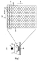
- Fig. 1 shows the appearance of a bioassay substrate according to a preferred embodiment of the present invention as viewed on the upper side.
- Fig. 2(A) is a schematic view, in a partially exaggerated manner, of the constitution of the substrate.
- Fig. 2(B) is a partial enlarged view showing the constitution of an embodiment of the part of a groove structure disposed on the substrate.
- the bioassay substrate 1 (hereinafter referred to simply as “the substrate 1") is formed of a base material adopted for a disk form substrate (disk) used for an optical information recording medium such as CD, DVD, and MD.
- the base material is formed in a disk shape from quartz glass, silicon, or a synthetic resin capable of being molded into the disk shape, such as polycarbonate and polystyrene, preferably a synthetic resin capable of being injection molded.
- a synthetic resin substrate can promise a lower running cost, as compared with the case of a glass chip, which has been conventionally used.
- the substrate 1 is provided at its center with a hole 2 for fixing onto a spindle provided in a substrate rotating means, which will be described later.
- a vapor-deposited aluminum layer about 40 nm in thickness is provided, which functions as a reflective film.
- the reflective film provides a surface reflectance of not less than 4%, from the substrate itself having a refractive index of not less than 1.5.
- a light-transmitting layer formed of transparent glass, transparent resin, or the like.
- the base material is a high reflectance material
- the surface of the base material itself functions as the reflective surface. Therefore, the reflective film may be omitted.
- the fluorescence intensity of a fluorescence-labeled target substance can be detected with better sensitivity.
- the light-transmitting layer is provided with groove structures 3 extending radially (as viewed on the upper side) from the central portion of the substrate 1, at predetermined intervals.
- detection surface sites S (see Fig. 2) surface-treated so as to enable solidification of detection substances are provided in the state of being aligned at predetermined intervals in the radial direction.
- the detection surface sites S may be formed at pit portions arranged in each of the groove structures 3, and may be formed over the whole range of the inside wall surface of each of the groove structures 3.
- detection surface sites S may be formed in cellular pits 3a, a plurality of which are aligned in the radial direction, and a plurality of rows each composed of the radially aligned pits 3a may be provided in the circumferential directions.
- symbol 4a in Fig. 3 denotes address pits or the like.
- the detection surface sites S have been appropriately selectively subjected to a preferable surface treatment for solidifying desired detection substances such as DNA probes.
- the detection surface sites S are surface treated with an amino group-containing silane coupling agent solution or a polylysine solution.
- the surface thereof is treated with plasma or by irradiation with DUV (deep UV, far ultraviolet rays), followed by the treatment with the amino group-containing silane coupling agent solution.
- the detection surfaces may be plated with copper, silver, aluminum, or gold by sputtering, and the surface of the sputtered metallic film may be coated with a substance having a functional group (active group) such as amino group, thiol group, carboxyl group, etc., cysteamine, storeptoavidin, or the like.
- a linker or linkers for solidification of the detection substances may be bonded to the detection surfaces, as required.
- the substrate 1 is preliminarily provided, along its rotational direction, with a multiplicity of address pits 4, 4 ⁇ formed by a optical disk mastering process.
- positional information and rotational synchronism information will be described.
- the groove structures 3 constituting the spotting and detecting positions are considered as user data areas, while the other areas are provided with arrays of synchronizing pits by a sample servo system or the like and are utilized also as tracking servo.
- an address portion (geographic address on the disk) is inserted immediately on the rear side thereof, to provide the positional information.
- the address portion begins with a sector mark constituting a leading pattern.
- the address is formed of a combination of a Variable Frequency Oscillator (VFO) for giving a rotational phase of the disk being actually rotated, an address mark for giving the start position of the address data, an identifier (ID) containing track and sector numbers, etc.
- VFO Variable Frequency Oscillator
- ID identifier
- wobblings may be formed on the track, and the meandering of the wobblings may be so adjusted as to provide clock information according to position, in which case addressing is performed by picking up the positional information on the disk.
- tracking servo can be performed by utilizing the frequency component of the wobblings.
- Fig. 4 is a block diagram briefly illustrating the constitution of the bioassay system.
- the bioassay system 10 shown in Fig. 4 is a bioassay system using the substrate 1 constituted as described above.
- the bioassay system 10 includes: a substrate rotating means 5 for rotatably supporting the substrate 1; a spotting device 6 for spotting detection substance-containing solutions D and a labeled target substance-containing solution T onto the detection surface sites S in a predetermined order and with predetermined timings, while rotating the substrate 1 by the substrate rotating means 5; a focus serve mechanism 7 for maintaining a fixed distance between the spotting device 6 and the substrate 1; and a tracking servo mechanism 8 for making the spotting of the solutions D and T follow up to the detection surface sites S on the substrate 1, based on the positional information and the rotational synchronism information obtained from the substrate 1.
- the bioassay system 10 includes a blue semiconductor laser 11 as an excitation light source.
- the system 10 also includes a red semiconductor laser 21 for the functions of the focus servo mechanism 7 and the tracking servo mechanism 8.
- the blue semiconductor laser 11 functions as the excitation light source for reading out the reaction information from the substrate 1.
- a laser beam B emitted from the blue semiconductor laser 11 is reflected at a right angle by a reflective mirror 12.
- the laser beam B is converted into a parallel beam by lenses 13 and 14 aligned in the propagating direction of the reflected beam.
- the parallel beam is reflected at a right angle by a reflective mirror 15 and is converted into circularly polarized light beam while passing through a ⁇ /4 plate 16.
- the circularly polarized light beam is enlarged in beam diameter by a concave lens 17 and a convex lens 18, is then reflected by a dichroic mirror 19, and is incident on an objective lens 20 disposed opposite to the substrate 1.
- the objective lens 20 is contained in a support body G.
- the dichroic mirror 19 is so designed as to reflect the light component in a wavelength band centered on the wavelength of the laser beam B emitted from the blue semiconductor laser 11 and to transmit the other light components. To be more specific, the dichroic mirror 19 is so designed as to reflect the laser beam B and to transmit the fluorescent light coming from the fluorescent material on the substrate 1 excited by the laser beam B, which will be described later.
- the substrate 1 held on the substrate rotating means 5 at a position on the lower side of the objective lens 20 is irradiated with the blue laser beam B through the objective lens 20.
- the fluorescent light emitted from the fluorescent material (which is bonded, as a label, to the target substance) excited by the blue laser beam B passes through the objective lens 20, further passes through the dichroic mirrors 19 and 26, is reflected at a right angle by a reflective mirror 27, and is detected by a photomultiplier and Avalanche photodiode detector (detector) 28.
- the dichroic mirror 26 is so designed as to reflect the light component in a wavelength band centered on the wavelength of the red laser beam R, which will be described later, and to transmit the other light components inclusive of the fluorescent light.
- the red laser beam R emitted from the red semiconductor laser denoted by symbol 21 is utilized for focusing, namely, for the function of maintaining a fixed distance between the substrate 1 and the objective lens 20.
- the red laser beam R is utilized for tracking servo, namely, for making the objective lens 20 follow up to the detection surface sites S in the groove structures 3 disposed in the substrate 1, based on the positional information and rotational synchronism information provided by the address pits 4 or/and the wobbled groove of the substrate 1.
- symbol 29 denotes a Position Sensor Detector (PSD) for adjusting the irradiation position of the red laser beam R.
- PSD Position Sensor Detector
- the laser beam R emitted from the red semiconductor laser 21 shown in Fig. 4 is converted into a parallel beam while passing through two lenses 22 and 23 aligned in the propagating direction of the laser beam R.
- the parallel beam is spectrally split by a polarized light beam splitter 24 disposed on the front side.
- One spectral component then passes through a ⁇ /4 plate 25, is reflected at a right angle by the dichroic mirror 26, and is incident on the objective lens 20, whereas the other spectral component is led to the PSD 29.
- the detection substance-containing solutions D or the labeled target substance-containing solution T is sequentially and accurately spotted onto the detection surface sites S with predetermined timings through ink jet nozzles 30 (hereinafter referred to simply as "nozzles 30") provided in the support body G integrally with the objective lens 20.
- Fig. 5(A) is a perspective view of the surroundings of the nozzles 30.
- Fig. 5(B) is an enlarged view of the nozzles 30.
- the objective lens 20 is provided in the center of a rectangular actuator holder H for supporting the objective lens 20, and the nozzle 30 is provided in a region of the holder H on the rear side of the objective lens 20.
- a plurality of the nozzles 30 may be provided.
- piezoelectric type ink jet nozzles are preferably adopted since they have the merit that it is easy to control the size of the droplets jetted, by varying the shape of the pulse impressed on the piezoelectric material.
- the arrow X in Figs. 5(A) and 5(B) indicates the moving direction (rotational direction) of the substrate 1.
- the nozzles 30 are composed of a plurality of nozzle groups 31 each of which constitutes a row of the nozzles 30 aligned in the radial direction Y and which are arrayed in the direction of arrow X.
- the nozzle group 31 is a set of nozzle holes 32, 32 ⁇ for simultaneously spotting the same detection substance-containing solution D. From the nozzle groups 31, 31 ⁇ , different kinds of detection substance-containing solutions D are sequentially spotted onto the corresponding detection surface sites S in the groove structures 3 of the substrate 1 on the lower side, simultaneously on the basis of each kind; subsequently, after a predetermined lapse of time, different kinds of or the same kind of labeled target substance-containing solution T is spotted onto the detection surface sites S simultaneously.
- L 0 represents the distance from the center of the objective lens to the nozzle group 31a in the first row
- L 1 represents the interval between the nozzle groups 31
- ⁇ represents the diameter of the droplets of the probe DNAs
- V 1 represents the linear velocity of the substrate 1
- W represents the distance from the nozzles 30 to the substrate 1
- V 2 represents the velocity of the droplets jetted from the nozzles 30.
- the target substance-containing solution can be spotted right onto the droplet of the detection substance-containing solution.
- a bioassay process which can be carried out by use of the substrate 1, will be briefly described based on Figs. 6(A) to 6(E), which illustrate the flow of the bioassay process that can be carried out using the substrate 1.
- the hole 2 of the substrate 1 is fixed to the spindle 51 (see Fig. 4) of the substrate rotating means 5 (see Fig. 4), and the substrate 1 is rotated.
- the detection substance-containing solutions D 1 , D 2 ⁇ are spotted from the nozzles 30 (nozzle groups 31) disposed opposite to the substrate 1 onto the predetermined detection surface sites S (see Fig. 2) provided on the substrate 1, based on the ink jet printing process (see Fig. 6(A)).
- the fluorescence-labeled target substance-containing solution T is spotted from the nozzles 30 (nozzle groups 31) disposed opposite to the substrate 1 onto the detection surface sites S by the ink jet printing process (see Fig. 6(B)).
- the substrate 1 is warmed for several hours in a thermohygrostat 9 (see Fig. 6(C)).
- washing liquid U is dripped from a washing nozzle N disposed opposite to the substrate 1, to remove from the detection surface sites S the labeled target substance that has not undergone the active coupling reaction.
- a washing liquid for example, a Saline-Sodium Citrate (SSC) buffer solution containing a surfactant SDS is used (see Fig. 6(D)).
- the substrate 1 is irradiated with the blue laser beam B to excite each of the detection surface sites S, the magnitude of fluorescence intensity is detected by the detector 28, and the results of the coupling reactions between the detection substances and the labeled target substance are judged. Finally, the fluorescence intensities for the individual detection surface sites S are subjected to A/D conversion, and the coupling reaction proportions are visualized by displaying the distribution thereof on the screen of a computer C (see Fig. 6(E)).
- a quartz glass substrate 12 cm in diameter was used.
- a groove with a track pitch of 50 ⁇ m, a duty of 70%, and a groove depth of 500 nm was formed by etching.
- the substrate surface was spin coated with a 0.3 wt% ethanol solution of a silane-coupling agent (product code: A1100, a product by Nippon Unitika K.K.), followed by drying in a bake furnace at 100°C for 2 hours.
- a silane-coupling agent product code: A1100, a product by Nippon Unitika K.K.
- the silane-treated substrate surface was spin-coated with a solution prepared by dissolving photobiotin (N-(4-azido-2-nitrophenyl)-N'-(3-biotinylaminopropyl)-N'-methyl-1,3-propanydiamine (acetate); a product by Sigma-Aldrich) in distilled water in a concentration of 10 ⁇ g/ml.
- photobiotin N-(4-azido-2-nitrophenyl)-N'-(3-biotinylaminopropyl)-N'-methyl-1,3-propanydiamine (acetate); a product by Sigma-Aldrich
- the photobiotin was irradiated with a blue laser beam from a blue semiconductor laser through an objective lens having an NA of 0.45 with modulation under the conditions of a wavelength of 405 nm, a power of 1 mW, and a frequency of 10 kHz, while maintaining a fixed distance between the substrate and the lens and in the manner of following up to the groove at a linear velocity of 1 m/s. Thereafter, the substrate thus treated was washed with distilled water, whereby photobiotin patterns were formed only in the irradiated areas, to obtain a negative type lithography.
- a photomultiplier product code: H5784-01; a product by Hamamatsu Photonics K.K.
- the fluorescence intensity was 120 mV on average for the 25 ⁇ g/ml solution, and 600 mV on average for the 250 ⁇ g/ml solution, with a fluorescence intensity ratio of 1/5.
Applications Claiming Priority (3)
| Application Number | Priority Date | Filing Date | Title |
|---|---|---|---|
| JP2002071984 | 2002-03-15 | ||
| JP2002071984 | 2002-03-15 | ||
| PCT/JP2003/003089 WO2003079013A1 (fr) | 2002-03-15 | 2003-03-14 | Substrat pour essai biologique, appareil d'essai biologique et appareil de lecture |
Publications (3)
| Publication Number | Publication Date |
|---|---|
| EP1486786A1 true EP1486786A1 (fr) | 2004-12-15 |
| EP1486786A4 EP1486786A4 (fr) | 2007-03-21 |
| EP1486786B1 EP1486786B1 (fr) | 2008-10-15 |
Family
ID=28035144
Family Applications (1)
| Application Number | Title | Priority Date | Filing Date |
|---|---|---|---|
| EP03708624A Expired - Fee Related EP1486786B1 (fr) | 2002-03-15 | 2003-03-14 | Substrat et procede pour un essai biologique |
Country Status (7)
| Country | Link |
|---|---|
| US (2) | US20050014286A1 (fr) |
| EP (1) | EP1486786B1 (fr) |
| KR (1) | KR100994306B1 (fr) |
| CN (1) | CN1288446C (fr) |
| DE (1) | DE60324112D1 (fr) |
| TW (1) | TWI252255B (fr) |
| WO (1) | WO2003079013A1 (fr) |
Cited By (3)
| Publication number | Priority date | Publication date | Assignee | Title |
|---|---|---|---|---|
| EP1888237B1 (fr) * | 2005-05-31 | 2016-01-20 | Gyros Patent Ab | Méthode pour déterminer l'identité d'un disque microfluidique et disque microfluidique |
| EP3043180A4 (fr) * | 2013-09-06 | 2017-04-19 | Nippon Light Metal Co., Ltd. | Substrat de biopuce |
| EP3358349A4 (fr) * | 2015-09-30 | 2018-08-08 | JVC KENWOOD Corporation | Dispositif d'analyse et procédé d'analyse |
Families Citing this family (15)
| Publication number | Priority date | Publication date | Assignee | Title |
|---|---|---|---|---|
| JP4193421B2 (ja) * | 2002-06-06 | 2008-12-10 | ソニー株式会社 | バイオアッセイ装置及びその製造方法、並びにバイオアッセイ方法 |
| JP4285206B2 (ja) * | 2003-11-11 | 2009-06-24 | ソニー株式会社 | 給電用配線が延設されたバイオアッセイ用基板 |
| JP4024828B2 (ja) * | 2004-03-04 | 2007-12-19 | 良一 今中 | マイクロアレイ及びスポッティング装置 |
| US20060088844A1 (en) * | 2004-10-22 | 2006-04-27 | Honeywell International Inc. | Real-time PCR microarray based on evanescent wave biosensor |
| JP4591195B2 (ja) * | 2005-05-19 | 2010-12-01 | ソニー株式会社 | バイオアッセイ用の基板と装置、並びに基板の製造方法 |
| IL176724A (en) * | 2006-07-06 | 2010-06-16 | Aviv Amirav | Method and apparatus for pulsed flow modulation gas chromatography mass spectrometry with supersonic molecular beams |
| US20080160557A1 (en) * | 2006-09-28 | 2008-07-03 | Cady Roger K | Diagnostic Test for Head and Facial Pain |
| US8124944B2 (en) * | 2007-01-17 | 2012-02-28 | Honeywell International Inc. | Microarray reader based on evanescent wave detection and method of reading a microarray |
| KR100806941B1 (ko) | 2007-08-09 | 2008-02-25 | (주)와이즈앤블루 | 랩언어디스크 판독 장치 |
| US8809810B2 (en) * | 2010-05-20 | 2014-08-19 | Honeywell International Inc. | Microarray reader based on evanescent wave detection |
| KR101530932B1 (ko) * | 2013-11-26 | 2015-06-25 | 한국과학기술연구원 | 패턴이 입력된 인코더를 포함하는 바이오 어세이용 마이크로 구조체 |
| CN104849114A (zh) * | 2015-05-13 | 2015-08-19 | 安徽农业大学 | 彗星实验专用载片 |
| USD841186S1 (en) * | 2015-12-23 | 2019-02-19 | Tunghai University | Biochip |
| EP4067868A1 (fr) * | 2016-02-04 | 2022-10-05 | Nova Biomedical Corporation | Un module de calibrage de la lumière |
| CN108802354B (zh) * | 2018-01-12 | 2021-04-16 | 丰能医药科技(上海)有限责任公司 | 尿液检测方法 |
Citations (4)
| Publication number | Priority date | Publication date | Assignee | Title |
|---|---|---|---|---|
| EP0417305A1 (fr) * | 1989-03-07 | 1991-03-20 | Idemitsu Petrochemical Co. Ltd. | Analyseur d'echantillon de liquide et procede d'analyse d'echantillon de liquide utilisant ledit analyseur |
| WO1998001533A1 (fr) * | 1996-07-08 | 1998-01-15 | Burstein Laboratories, Inc. | Procede et dispositif a element de signal clivable |
| WO1999024822A1 (fr) * | 1997-11-12 | 1999-05-20 | Functional Genetics, Inc. | Dispositifs et methodes de determination rapide d'ensembles |
| US6172952B1 (en) * | 1997-06-11 | 2001-01-09 | Matsushita Electric Industrial Co., Ltd. | Optical disk device with abnormal jump detection |
Family Cites Families (15)
| Publication number | Priority date | Publication date | Assignee | Title |
|---|---|---|---|---|
| JP3063596B2 (ja) * | 1995-11-24 | 2000-07-12 | 三菱電機株式会社 | 光ディスク装置および光ディスク |
| JPH09231699A (ja) * | 1996-02-20 | 1997-09-05 | Sony Corp | 光ディスク及びその光ディスクドライブ装置 |
| JP3938982B2 (ja) | 1997-08-29 | 2007-06-27 | オリンパス株式会社 | Dnaキャピラリィ |
| JP3346727B2 (ja) * | 1997-09-19 | 2002-11-18 | 日立ソフトウエアエンジニアリング株式会社 | バイオチップ及びバイオチップ読取り装置 |
| US5994150A (en) | 1997-11-19 | 1999-11-30 | Imation Corp. | Optical assaying method and system having rotatable sensor disk with multiple sensing regions |
| JP2002501174A (ja) * | 1997-12-30 | 2002-01-15 | ルマクル,ジョゼ | ディスク表面上に固定された捕獲分子を含む方法 |
| US7014815B1 (en) * | 1998-10-30 | 2006-03-21 | Burstein Technologies, Inc. | Trackable optical discs with concurrently readable nonoperational features |
| JP3746658B2 (ja) * | 1999-04-12 | 2006-02-15 | 株式会社日立製作所 | 微粒子を用いたプローブアレーの作製方法及び装置 |
| AU1429701A (en) * | 1999-07-16 | 2001-02-05 | Board Of Regents, The University Of Texas System | General signaling protocols for chemical receptors in immobilized matrices |
| JP2001238674A (ja) * | 2000-02-29 | 2001-09-04 | Nikon Corp | Dnaアレイ、dnaアレイ読み取り装置、及びdnaアレイ製造装置 |
| JP2002014106A (ja) * | 2000-06-29 | 2002-01-18 | Nippon Laser & Electronics Lab | 試料ディスク及び試料解析装置 |
| WO2002006836A2 (fr) | 2000-07-19 | 2002-01-24 | Fraunhofer-Gesellschaft zur Förderung der angewandten Forschung e.V. | Dispositif servant a effectuer des essais de fluorescence biochimiques |
| JP2002040036A (ja) * | 2000-07-28 | 2002-02-06 | Mitsubishi Chemicals Corp | スポッティングヘッド,スポッティング装置及びスポッティング方法 |
| JP4378042B2 (ja) * | 2000-08-31 | 2009-12-02 | キヤノン株式会社 | 検体試料中の対象成分の検出方法、およびそれに用いる検出用基板 |
| JP2002250726A (ja) * | 2000-12-08 | 2002-09-06 | Toray Ind Inc | ポリマー配列固定化ディスクおよび固定化ポリマー配列による検出方法 |
-
2003
- 2003-03-14 WO PCT/JP2003/003089 patent/WO2003079013A1/fr active Application Filing
- 2003-03-14 KR KR1020037014782A patent/KR100994306B1/ko not_active IP Right Cessation
- 2003-03-14 TW TW092105669A patent/TWI252255B/zh not_active IP Right Cessation
- 2003-03-14 US US10/477,587 patent/US20050014286A1/en not_active Abandoned
- 2003-03-14 DE DE60324112T patent/DE60324112D1/de not_active Expired - Lifetime
- 2003-03-14 EP EP03708624A patent/EP1486786B1/fr not_active Expired - Fee Related
- 2003-03-14 CN CNB038003953A patent/CN1288446C/zh not_active Expired - Fee Related
-
2010
- 2010-09-22 US US12/888,102 patent/US8211380B2/en not_active Expired - Lifetime
Patent Citations (4)
| Publication number | Priority date | Publication date | Assignee | Title |
|---|---|---|---|---|
| EP0417305A1 (fr) * | 1989-03-07 | 1991-03-20 | Idemitsu Petrochemical Co. Ltd. | Analyseur d'echantillon de liquide et procede d'analyse d'echantillon de liquide utilisant ledit analyseur |
| WO1998001533A1 (fr) * | 1996-07-08 | 1998-01-15 | Burstein Laboratories, Inc. | Procede et dispositif a element de signal clivable |
| US6172952B1 (en) * | 1997-06-11 | 2001-01-09 | Matsushita Electric Industrial Co., Ltd. | Optical disk device with abnormal jump detection |
| WO1999024822A1 (fr) * | 1997-11-12 | 1999-05-20 | Functional Genetics, Inc. | Dispositifs et methodes de determination rapide d'ensembles |
Non-Patent Citations (1)
| Title |
|---|
| See also references of WO03079013A1 * |
Cited By (5)
| Publication number | Priority date | Publication date | Assignee | Title |
|---|---|---|---|---|
| EP1888237B1 (fr) * | 2005-05-31 | 2016-01-20 | Gyros Patent Ab | Méthode pour déterminer l'identité d'un disque microfluidique et disque microfluidique |
| EP3043180A4 (fr) * | 2013-09-06 | 2017-04-19 | Nippon Light Metal Co., Ltd. | Substrat de biopuce |
| EP3546942A1 (fr) * | 2013-09-06 | 2019-10-02 | Nippon Light Metal Company, Ltd. | Biopuce |
| EP3358349A4 (fr) * | 2015-09-30 | 2018-08-08 | JVC KENWOOD Corporation | Dispositif d'analyse et procédé d'analyse |
| US11300580B2 (en) | 2015-09-30 | 2022-04-12 | JVC Kenwood Corporation | Analysis device and analysis method |
Also Published As
| Publication number | Publication date |
|---|---|
| US20050014286A1 (en) | 2005-01-20 |
| CN1547668A (zh) | 2004-11-17 |
| US20110008879A1 (en) | 2011-01-13 |
| DE60324112D1 (de) | 2008-11-27 |
| CN1288446C (zh) | 2006-12-06 |
| US8211380B2 (en) | 2012-07-03 |
| KR20040099098A (ko) | 2004-11-26 |
| TW200305648A (en) | 2003-11-01 |
| EP1486786B1 (fr) | 2008-10-15 |
| WO2003079013A1 (fr) | 2003-09-25 |
| EP1486786A4 (fr) | 2007-03-21 |
| TWI252255B (en) | 2006-04-01 |
| KR100994306B1 (ko) | 2010-11-12 |
Similar Documents
| Publication | Publication Date | Title |
|---|---|---|
| US8211380B2 (en) | Bio-assay substrate, bio-assay apparatus, and reading apparatus | |
| KR100379411B1 (ko) | 바이오칩 및 그의 생체 물질 패터닝 및 측정 방법 | |
| US6623696B1 (en) | Biochip, apparatus for detecting biomaterials using the same, and method therefor | |
| US20020008871A1 (en) | Method and device for detecting optical properties, especially luminescence reactions and refraction behavior of molecules which are directly or indirectly bound on a support | |
| JP4591195B2 (ja) | バイオアッセイ用の基板と装置、並びに基板の製造方法 | |
| TWI237115B (en) | Bioassay unit and substrate for bioassay | |
| JP2001238674A (ja) | Dnaアレイ、dnaアレイ読み取り装置、及びdnaアレイ製造装置 | |
| US8080408B2 (en) | Bioassay substrate and bioassay method | |
| CN100387990C (zh) | 生物测定方法、生物测定设备和生物测定衬底 | |
| JP4200801B2 (ja) | バイオアッセイ用基板 | |
| US20050255474A1 (en) | Substrate for bioassay, substrate information reader, and substrate information reading method | |
| JP4321085B2 (ja) | バイオアッセイ用基板とバイオアッセイ装置及び読み取り装置 | |
| US20070141576A1 (en) | Biological chip and use thereof | |
| US20080139395A1 (en) | Microarray and Spotting Apparatus | |
| JP2002250726A (ja) | ポリマー配列固定化ディスクおよび固定化ポリマー配列による検出方法 | |
| JP4218274B2 (ja) | バイオアッセイ装置 | |
| JP2003344398A (ja) | バイオアッセイ方法及びバイオアッセイ装置 | |
| KR101162365B1 (ko) | 바이오 어세이 방법, 바이오 어세이 장치 및 바이오어세이 기판 | |
| JPWO2005056145A1 (ja) | 生物学的チップおよびその利用 |
Legal Events
| Date | Code | Title | Description |
|---|---|---|---|
| PUAI | Public reference made under article 153(3) epc to a published international application that has entered the european phase |
Free format text: ORIGINAL CODE: 0009012 |
|
| 17P | Request for examination filed |
Effective date: 20031031 |
|
| AK | Designated contracting states |
Kind code of ref document: A1 Designated state(s): AT BE BG CH CY CZ DE DK EE ES FI FR GB GR HU IE IT LI LU MC NL PT RO SE SI SK TR |
|
| A4 | Supplementary search report drawn up and despatched |
Effective date: 20070221 |
|
| RIC1 | Information provided on ipc code assigned before grant |
Ipc: G01N 35/00 20060101ALI20070215BHEP Ipc: G01N 33/543 20060101ALI20070215BHEP Ipc: G01N 37/00 20060101ALI20070215BHEP Ipc: G01N 33/53 20060101AFI20030930BHEP |
|
| 17Q | First examination report despatched |
Effective date: 20070608 |
|
| RTI1 | Title (correction) |
Free format text: BIO-ASSAY SUBSTRATE AND METHOD |
|
| GRAP | Despatch of communication of intention to grant a patent |
Free format text: ORIGINAL CODE: EPIDOSNIGR1 |
|
| RBV | Designated contracting states (corrected) |
Designated state(s): DE FR GB |
|
| GRAS | Grant fee paid |
Free format text: ORIGINAL CODE: EPIDOSNIGR3 |
|
| GRAA | (expected) grant |
Free format text: ORIGINAL CODE: 0009210 |
|
| AK | Designated contracting states |
Kind code of ref document: B1 Designated state(s): DE FR GB |
|
| REG | Reference to a national code |
Ref country code: GB Ref legal event code: FG4D |
|
| REF | Corresponds to: |
Ref document number: 60324112 Country of ref document: DE Date of ref document: 20081127 Kind code of ref document: P |
|
| PLBE | No opposition filed within time limit |
Free format text: ORIGINAL CODE: 0009261 |
|
| STAA | Information on the status of an ep patent application or granted ep patent |
Free format text: STATUS: NO OPPOSITION FILED WITHIN TIME LIMIT |
|
| 26N | No opposition filed |
Effective date: 20090716 |
|
| REG | Reference to a national code |
Ref country code: GB Ref legal event code: 746 Effective date: 20091130 |
|
| PGFP | Annual fee paid to national office [announced via postgrant information from national office to epo] |
Ref country code: FR Payment date: 20140319 Year of fee payment: 12 |
|
| PGFP | Annual fee paid to national office [announced via postgrant information from national office to epo] |
Ref country code: GB Payment date: 20140319 Year of fee payment: 12 |
|
| GBPC | Gb: european patent ceased through non-payment of renewal fee |
Effective date: 20150314 |
|
| REG | Reference to a national code |
Ref country code: FR Ref legal event code: ST Effective date: 20151130 |
|
| PG25 | Lapsed in a contracting state [announced via postgrant information from national office to epo] |
Ref country code: GB Free format text: LAPSE BECAUSE OF NON-PAYMENT OF DUE FEES Effective date: 20150314 |
|
| PG25 | Lapsed in a contracting state [announced via postgrant information from national office to epo] |
Ref country code: FR Free format text: LAPSE BECAUSE OF NON-PAYMENT OF DUE FEES Effective date: 20150331 |
|
| PGFP | Annual fee paid to national office [announced via postgrant information from national office to epo] |
Ref country code: DE Payment date: 20200320 Year of fee payment: 18 |
|
| REG | Reference to a national code |
Ref country code: DE Ref legal event code: R119 Ref document number: 60324112 Country of ref document: DE |
|
| PG25 | Lapsed in a contracting state [announced via postgrant information from national office to epo] |
Ref country code: DE Free format text: LAPSE BECAUSE OF NON-PAYMENT OF DUE FEES Effective date: 20211001 |