EP1484528A2 - Schwingungsdämpfer für Fahrzeuge - Google Patents
Schwingungsdämpfer für Fahrzeuge Download PDFInfo
- Publication number
- EP1484528A2 EP1484528A2 EP04011884A EP04011884A EP1484528A2 EP 1484528 A2 EP1484528 A2 EP 1484528A2 EP 04011884 A EP04011884 A EP 04011884A EP 04011884 A EP04011884 A EP 04011884A EP 1484528 A2 EP1484528 A2 EP 1484528A2
- Authority
- EP
- European Patent Office
- Prior art keywords
- vibration damper
- piston rod
- piston
- damper according
- stop element
- Prior art date
- Legal status (The legal status is an assumption and is not a legal conclusion. Google has not performed a legal analysis and makes no representation as to the accuracy of the status listed.)
- Granted
Links
- 230000003014 reinforcing effect Effects 0.000 claims description 6
- 238000013016 damping Methods 0.000 claims description 4
- 230000002787 reinforcement Effects 0.000 claims description 4
- 238000004073 vulcanization Methods 0.000 claims description 3
- 239000012530 fluid Substances 0.000 claims description 2
- 150000001875 compounds Chemical class 0.000 description 1
- 210000003746 feather Anatomy 0.000 description 1
Images

Classifications
-
- F—MECHANICAL ENGINEERING; LIGHTING; HEATING; WEAPONS; BLASTING
- F16—ENGINEERING ELEMENTS AND UNITS; GENERAL MEASURES FOR PRODUCING AND MAINTAINING EFFECTIVE FUNCTIONING OF MACHINES OR INSTALLATIONS; THERMAL INSULATION IN GENERAL
- F16F—SPRINGS; SHOCK-ABSORBERS; MEANS FOR DAMPING VIBRATION
- F16F9/00—Springs, vibration-dampers, shock-absorbers, or similarly-constructed movement-dampers using a fluid or the equivalent as damping medium
- F16F9/32—Details
- F16F9/58—Stroke limiting stops, e.g. arranged on the piston rod outside the cylinder
- F16F9/585—Stroke limiting stops, e.g. arranged on the piston rod outside the cylinder within the cylinder, in contact with working fluid
Definitions
- the invention relates to a vibration damper for vehicles, consisting from a working cylinder in which a piston over a piston rod is guided axially, the piston of the working cylinder in two with damping fluid filled working spaces divided, being between the piston and a Piston rod guide a pull stop is provided.
- Vibration dampers are already known (DE-GM 85 20 989), in which a support ring is arranged on the piston rod, which as a contact surface for an elastic stop ring is used.
- This stop ring comes from a certain one Extension of the piston rod on the cylinder inner face of the Piston rod guide to the system so that a pull stop is formed.
- the disadvantage here is that the elastic stop ring not only in the axial direction, but also deformed in the radial direction when axially pressurized becomes. It can occur that the elastic stop ring over the admissible shear stresses are deformed and thus destroyed.
- train stop devices are known (EP 119 197 B1, EP 120.005 B1), which also have an elastic ring as a stop is used, the angular brackets on the piston rod it is appropriate that with an axial pressurization not only an axial but also a radial deformation of the elastic ring occurs.
- the invention provides that between a bearing attached to the piston rod and the piston rod guide a chambered tension stop element is arranged:
- the tension stop element consists of an elastic element, which with a reinforcing part is surrounded. It is advantageous that the height of the reinforcing part is the block length of the elastic element defined. This means that even with increasing Load achieve a limited deformation so that the allowable Shear stresses are not exceeded.
- the elastic part and the reinforcing part are firmly connected, it is advantageously provided that the elastic Part is connected to the reinforcement part by vulcanization.
- the elastic Part is connected to the reinforcement part by vulcanization.
- Another embodiment provides that the tension stop element on the Piston rod is guided and axially movable.
- the tension stop element is on at least one end face is provided with at least one elevation.
- the end region of the spring is provided with a support element for support on the train stop element.
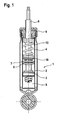
- the vibration damper 1 shown in Figure 1 consists essentially of the working cylinder 2, which is axially movably guided on the piston rod 6 Piston 3, the piston 3 divides the working cylinder 2 into the upper working space 4 and the lower work area 5.
- the damping piston 3 are usually Damping valves (not shown) for the respective flow direction intended.
- the piston rod 6 is led out through the piston rod guide 9, being between the piston rod guide 9 and the piston 3
- Ceianschlagelement 7 is provided.
- the Buchanschlagelement 7 is on the the side facing the piston 3 is supported by the support 8 and is in the direction the.
- Piston rod guide 9 at least partially axially movable on the piston rod 6 led.
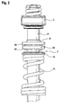
- a piston rod 6 with the one fixed to it is shown in detail in FIG Piston 3 shown, between the support 8 and the support element 16 of the spring 13, the tension stop element 7 is arranged.
- the tension stop element 7 is arranged.
- this embodiment is the Buchanschlagelement 10 on both sides of the respective Front 15 provided with elevations 14.
- These surveys 14 belong to the elastic element 11, which is shown in detail in Figures 3 and 4 is.
- FIGS. 3 and 4 show the pull stop element 10 as an individual part, the armoring part 12 the elastic element 11 radially outwards limited.
- the elastic element 11 and the reinforcement part 12 are included formed in one piece, they can be connected by vulcanization become. Elevations are on the respective end face 15 of the elastic element 11 14 distributed over the circumference, opposite the support the support 8 and the support element 16 of the vibration damper 1 serve.
Landscapes
- Engineering & Computer Science (AREA)
- General Engineering & Computer Science (AREA)
- Mechanical Engineering (AREA)
- Fluid-Damping Devices (AREA)
- Vibration Prevention Devices (AREA)
- Superstructure Of Vehicle (AREA)
Abstract
Description
- 1 -
- Schwingungsdämpfer
- 2 -
- Arbeitszylinder
- 3 -
- Kolben
- 4 -
- oberer Arbeitsraum
- 5 -
- unterer Arbeitsraum
- 6 -
- Kolbenstange
- 7 -
- Zuganschlagelement
- 8 -
- Auflager
- 9 -
- Kolbenstangenführung
- 10 -
- Zuganschlagelement
- 11 -
- elastisches Element
- 12 -
- Armierungsteil
- 13 -
- Feder
- 14 -
- Erhebung
- 15 -
- Stirnseite
- 16 -
- Abstützelement
Claims (9)
- Schwingungsdämpfer für Fahrzeuge, bestehend aus einem Arbeitszylinder, in dem ein Kolben über eine Kolbenstange axial geführt ist, wobei der Kolben den Arbeitszylinder in zwei mit Dämpfungsflüssigkeit gefüllte Arbeitsräume unterteilt, wobei zwischen dem Kolben und einer Kolbenstangenführung ein Zuganschlag vorgesehen ist,
dadurch gekennzeichnet, dass zwischen einem mit der Kolbenstange (6) befestigten Auflager (8) und der Kolbenstangenführung (9) ein gekammertes Zuganschlagelement (10) angeordnet ist. - Schwingungsdämpfer nach Anspruch 1,
dadurch gekennzeichnet, dass das Zuganschlagelement (10) aus einem elastischen Element (11) besteht, welches mit einem Armierungsteil (12) umgeben ist. - Schwingungsdämpfer nach Anspruch 1,
dadurch gekennzeichnet, dass das elastische Teil (11) und das Armierungsteil (12) fest miteinander verbunden sind. - Schwingungsdämpfer nach Anspruch 3,
dadurch gekennzeichnet, dass das elastische Teil (11) mit dem Armierungsteil (12) durch Vulkanisation verbunden ist. - Schwingungsdämpfer nach Anspruch 1,
dadurch gekennzeichnet, dass zwischen dem Zuganschlagelement (10) und der Kolbenstangenführung (9) eine Feder (13) angeordnet ist. - Schwingungsdämpfer nach Anspruch 1,
dadurch gekennzeichnet, dass das Zuganschlagelement (10) auf der Kolbenstange (6) geführt und axial beweglich angeordnet ist. - Schwingungsdämpfer nach Anspruch 1,
dadurch gekennzeichnet, dass das Zuganschlagelement (10) auf mindestens einer Stirnseite (15) mit mindestens einer Erhebung (14) versehen ist. - Schwingungsdämpfer nach Anspruch 6,
dadurch gekennzeichnet, dass mehrere Erhebungen (14) vorgesehen sind, die über den Umfang der Stirnseite (15) verteilt angeordnet sind. - Schwingungsdämpfer nach Anspruch 4,
dadurch gekennzeichnet, dass der Endbereich der Feder (13) mit einem Abstützelement (16) zur Abstützung am Zuganschlagelement (10) versehen ist.
Applications Claiming Priority (2)
| Application Number | Priority Date | Filing Date | Title |
|---|---|---|---|
| DE10325730A DE10325730B4 (de) | 2003-06-06 | 2003-06-06 | Schwingungsdämpfer für Fahrzeuge |
| DE10325730 | 2003-06-06 |
Publications (3)
| Publication Number | Publication Date |
|---|---|
| EP1484528A2 true EP1484528A2 (de) | 2004-12-08 |
| EP1484528A3 EP1484528A3 (de) | 2005-01-19 |
| EP1484528B1 EP1484528B1 (de) | 2006-09-13 |
Family
ID=33154582
Family Applications (1)
| Application Number | Title | Priority Date | Filing Date |
|---|---|---|---|
| EP04011884A Expired - Lifetime EP1484528B1 (de) | 2003-06-06 | 2004-05-19 | Schwingungsdämpfer für Fahrzeuge |
Country Status (4)
| Country | Link |
|---|---|
| US (1) | US7866452B2 (de) |
| EP (1) | EP1484528B1 (de) |
| AT (1) | ATE339633T1 (de) |
| DE (2) | DE10325730B4 (de) |
Families Citing this family (17)
| Publication number | Priority date | Publication date | Assignee | Title |
|---|---|---|---|---|
| DE102005009213B4 (de) * | 2005-02-25 | 2008-07-31 | Thyssenkrupp Bilstein Suspension Gmbh | Hydraulischer Schwingungsdämpfer mit ausknicksicherer Zuganschlagfeder |
| JP5000235B2 (ja) * | 2006-08-25 | 2012-08-15 | 日産自動車株式会社 | シリンダ装置 |
| DE102006046333B3 (de) * | 2006-09-28 | 2008-02-07 | Thyssenkrupp Bilstein Suspension Gmbh | Schwingungsdämpfer mit amplitudenabhängiger Dämpfungseinrichtung, insbesondere für Schwingungsdämpfer mit großem Durchmesser |
| US20090260188A1 (en) * | 2008-04-17 | 2009-10-22 | Gm Global Technology Operations, Inc. | Wide Opening Vehicle Door with Easy-Reach Feature |
| JP2011094749A (ja) * | 2009-10-30 | 2011-05-12 | Hitachi Automotive Systems Ltd | 緩衝器 |
| JP5667482B2 (ja) * | 2011-03-17 | 2015-02-12 | カヤバ工業株式会社 | シリンダ装置 |
| WO2013010921A2 (en) | 2011-07-20 | 2013-01-24 | Kanioez Adil | Shock absorber having an improved friction element |
| KR101337585B1 (ko) * | 2011-11-10 | 2013-12-16 | 주식회사 만도 | 쇽업소버 |
| JP5964200B2 (ja) * | 2012-10-19 | 2016-08-03 | Nok株式会社 | リバウンドラバー |
| US9618073B2 (en) | 2013-11-15 | 2017-04-11 | Aksistem Elektromekanik San. ve Tic. Ltd. Sti. | Shock absorber having an improved friction element |
| US9091320B1 (en) | 2014-01-08 | 2015-07-28 | Thyssenkrupp Bilstein Of America, Inc. | Multi-stage shock absorber |
| US10087688B2 (en) * | 2015-02-12 | 2018-10-02 | Baker Hughes, A Ge Company, Llc | Energy absorption system for subterranean tool high impact loads |
| JP6616672B2 (ja) * | 2015-11-20 | 2019-12-04 | Kyb株式会社 | バンプストッパ、及び緩衝器 |
| WO2017121418A1 (en) | 2016-01-11 | 2017-07-20 | Čvut V Praze, Fakulta Strojni | Hydraulic damper |
| CZ306644B6 (cs) | 2016-02-11 | 2017-04-12 | ÄŚVUT v Praze, Fakulta strojnĂ | Způsob řízení tlumicí síly hydraulického tlumiče a hydraulický tlumič |
| DE102016215773B4 (de) | 2016-08-23 | 2025-04-10 | Thyssenkrupp Ag | Anschlagpuffer für einen Schwingungsdämpfer und einen Schwingungsdämpfer für Kraftfahrzeuge |
| DE102018207909B3 (de) | 2018-05-18 | 2019-09-05 | Zf Friedrichshafen Ag | Zuganschlag für einen Schwingungsdämpfer |
Citations (3)
| Publication number | Priority date | Publication date | Assignee | Title |
|---|---|---|---|---|
| DE8520989U1 (de) | 1985-07-20 | 1985-09-19 | Fichtel & Sachs Ag, 8720 Schweinfurt | Schwingungsdämpfer für Fahrzeuge |
| EP0119197B1 (de) | 1982-09-20 | 1988-11-02 | Ford Motor Company Limited | Endanschlag für einen teleskopischen hydraulischen Stossdämpfer |
| EP0120005B1 (de) | 1982-09-20 | 1989-02-01 | Ford Motor Company Limited | Stossdämpfer mit einem hydromechanischen endanschlag |
Family Cites Families (21)
| Publication number | Priority date | Publication date | Assignee | Title |
|---|---|---|---|---|
| US2782765A (en) * | 1954-07-28 | 1957-02-26 | Robinson Products Inc | Air cylinder |
| US2984529A (en) * | 1959-01-26 | 1961-05-16 | Baldwin Rubber Co | Unitary sealed piston |
| DE1816598U (de) * | 1960-06-25 | 1960-08-11 | Auto Union Gmbh | Stossdaempfer, insbesondere fuer kraftfahrzeuge. |
| DE1145445B (de) * | 1960-08-26 | 1963-03-14 | Lemfoerder Metallwarengesellsc | Zusatzfederung fuer Teleskop-Stossdaempfer |
| US3465650A (en) * | 1967-01-16 | 1969-09-09 | William Gluck | Shock absorbing means for piston and cylinder or the like |
| FR1584110A (de) * | 1968-08-06 | 1969-12-12 | ||
| DE1816598A1 (de) | 1968-12-23 | 1970-06-25 | Pantenburg Dipl Ing Axel | Selbstanlaufende Synchronuhr mit Netzausfall-Anzeige |
| DE2853914A1 (de) * | 1978-12-14 | 1980-07-03 | Fichtel & Sachs Ag | Schwingungsdaempfer oder federbein mit einem hydraulisch-mechanischen zuganschlag |
| US4483044A (en) * | 1982-09-27 | 1984-11-20 | National Manufacturing Co. | Pneumatic door closer having resilient braking sleeve and cooperating piston rod incremental braking enlargements |
| DE3500101C1 (de) * | 1985-01-03 | 1986-07-24 | Ford-Werke AG, 5000 Köln | Hydraulischer Zweirohr-Schwingungsdämpfer |
| DE3643056A1 (de) * | 1986-12-17 | 1988-06-30 | Bayerische Motoren Werke Ag | Stossdaempfer |
| US5024301A (en) * | 1990-05-23 | 1991-06-18 | Ford Motor Company | Hydraulic rebound stop assembly for a shock absorber |
| DE4036522C1 (de) * | 1990-11-16 | 1991-10-10 | Boge Ag | Hydraulischer Schwingungsdämpfer |
| JPH0735187A (ja) * | 1993-07-20 | 1995-02-03 | Suzuki Motor Corp | ショックアブソーバ構造 |
| GB9407464D0 (en) * | 1994-04-15 | 1994-06-08 | Acg Espana Sa | Suspension strut |
| JPH08109943A (ja) * | 1994-10-13 | 1996-04-30 | Nippon Mektron Ltd | バンプストッパ− |
| US5667041A (en) * | 1995-11-03 | 1997-09-16 | General Motors Corporation | Suspension strut with hydraulic stop |
| US5810130A (en) * | 1997-03-14 | 1998-09-22 | General Motors Corporation | Suspension damper with rebound cut-off |
| US5984060A (en) * | 1997-08-25 | 1999-11-16 | General Motors Corporation | Monotube strut assembly |
| JP4442842B2 (ja) * | 2000-07-28 | 2010-03-31 | 株式会社ショーワ | ダンパのリバウンドストッパ構造 |
| US6691840B1 (en) * | 2003-02-07 | 2004-02-17 | Delphi Technologies, Inc. | MR damper with rebound cut-off feature |
-
2003
- 2003-06-06 DE DE10325730A patent/DE10325730B4/de not_active Expired - Fee Related
-
2004
- 2004-05-19 EP EP04011884A patent/EP1484528B1/de not_active Expired - Lifetime
- 2004-05-19 DE DE502004001444T patent/DE502004001444D1/de not_active Expired - Lifetime
- 2004-05-19 AT AT04011884T patent/ATE339633T1/de not_active IP Right Cessation
- 2004-06-04 US US10/861,053 patent/US7866452B2/en not_active Expired - Fee Related
Patent Citations (3)
| Publication number | Priority date | Publication date | Assignee | Title |
|---|---|---|---|---|
| EP0119197B1 (de) | 1982-09-20 | 1988-11-02 | Ford Motor Company Limited | Endanschlag für einen teleskopischen hydraulischen Stossdämpfer |
| EP0120005B1 (de) | 1982-09-20 | 1989-02-01 | Ford Motor Company Limited | Stossdämpfer mit einem hydromechanischen endanschlag |
| DE8520989U1 (de) | 1985-07-20 | 1985-09-19 | Fichtel & Sachs Ag, 8720 Schweinfurt | Schwingungsdämpfer für Fahrzeuge |
Also Published As
| Publication number | Publication date |
|---|---|
| DE502004001444D1 (de) | 2006-10-26 |
| US20050016805A1 (en) | 2005-01-27 |
| DE10325730B4 (de) | 2006-02-02 |
| US7866452B2 (en) | 2011-01-11 |
| EP1484528B1 (de) | 2006-09-13 |
| EP1484528A3 (de) | 2005-01-19 |
| DE10325730A1 (de) | 2005-01-20 |
| ATE339633T1 (de) | 2006-10-15 |
Similar Documents
| Publication | Publication Date | Title |
|---|---|---|
| EP1484528A2 (de) | Schwingungsdämpfer für Fahrzeuge | |
| DE2726676C2 (de) | Federelement zur elastischen Lagerung von Antriebs- oder sonstigen Aggregaten | |
| EP3277976B1 (de) | Dämpfventil für einen schwingungsdämpfer | |
| DE102019212966A1 (de) | Dämpfventileinrichtung mit progressiver Dämpfkraftkennlinie | |
| EP0886078A2 (de) | Reibungsdämpfer mit einem Elastomerfederlement | |
| EP0175105B1 (de) | Membranpumpe, insbesondere zum Dosieren von Flüssigkeiten | |
| EP1152166A1 (de) | Stossdämpfer mit amplitudenabhängiger Dämpfung | |
| DE102016210789B4 (de) | Dämpfventil für einen Schwingungsdämpfer | |
| DE2853914A1 (de) | Schwingungsdaempfer oder federbein mit einem hydraulisch-mechanischen zuganschlag | |
| DE1813038C3 (de) | Ventil für einen hydraulischen Teleskop-Stoßdämpfer | |
| DE102017216662B4 (de) | Dämpfungsanordnung für einen Schwingungsdämpfer eines Kraftfahrzeugs | |
| DE102004007960B4 (de) | Kolben-Zylinder-Aggregat | |
| DE102016224353A1 (de) | Hydraulischer Endanschlag für einen Schwingungsdämpfer | |
| WO2018054600A1 (de) | Dämpfventil für einen schwingungsdämpfer | |
| DE102014203842A1 (de) | Ventil, insbesondere für einen Schwingungsdämpfer | |
| DE69916132T2 (de) | Luftfeder und befestigung dafür | |
| DE102006005621A1 (de) | Anschlagfeder für ein Kolben-Zylinderaggregat | |
| DE102018214148A1 (de) | Dämpfventil für einen Schwingungsdämpfer | |
| DE102017216661A1 (de) | Dämpfungsanordnung für einen Schwingungsdämpfer eines Kraftfahrzeugs | |
| EP1979646B1 (de) | Luftfeder- und dämpfereinheit mit zuganschlag | |
| DE102006015605B4 (de) | Kolbenanordnung | |
| DE102004005063A1 (de) | Kolben-Zylinder-Aggregat | |
| DE102005023412B4 (de) | Einrichtung zur Lagerung einer ringförmigen Bremsscheibe auf einer Radnabe | |
| DE102013226410A1 (de) | Mechanische Schwingungsdämpfereinrichtung für schwingungsbeaufschlagte Maschinenteile | |
| DE102023205445A1 (de) | Schwingungsdämpfer mit einem hydraulischen Druckanschlag |
Legal Events
| Date | Code | Title | Description |
|---|---|---|---|
| PUAI | Public reference made under article 153(3) epc to a published international application that has entered the european phase |
Free format text: ORIGINAL CODE: 0009012 |
|
| PUAL | Search report despatched |
Free format text: ORIGINAL CODE: 0009013 |
|
| AK | Designated contracting states |
Kind code of ref document: A2 Designated state(s): AT BE BG CH CY CZ DE DK EE ES FI FR GB GR HU IE IT LI LU MC NL PL PT RO SE SI SK TR |
|
| AX | Request for extension of the european patent |
Extension state: AL HR LT LV MK |
|
| AK | Designated contracting states |
Kind code of ref document: A3 Designated state(s): AT BE BG CH CY CZ DE DK EE ES FI FR GB GR HU IE IT LI LU MC NL PL PT RO SE SI SK TR |
|
| AX | Request for extension of the european patent |
Extension state: AL HR LT LV MK |
|
| 17P | Request for examination filed |
Effective date: 20050407 |
|
| 17Q | First examination report despatched |
Effective date: 20050513 |
|
| AKX | Designation fees paid |
Designated state(s): AT BE BG CH CY CZ DE DK EE ES FI FR GB GR HU IE IT LI LU MC NL PL PT RO SE SI SK TR |
|
| GRAP | Despatch of communication of intention to grant a patent |
Free format text: ORIGINAL CODE: EPIDOSNIGR1 |
|
| GRAS | Grant fee paid |
Free format text: ORIGINAL CODE: EPIDOSNIGR3 |
|
| GRAA | (expected) grant |
Free format text: ORIGINAL CODE: 0009210 |
|
| AK | Designated contracting states |
Kind code of ref document: B1 Designated state(s): AT BE BG CH CY CZ DE DK EE ES FI FR GB GR HU IE IT LI LU MC NL PL PT RO SE SI SK TR |
|
| PG25 | Lapsed in a contracting state [announced via postgrant information from national office to epo] |
Ref country code: IT Free format text: LAPSE BECAUSE OF FAILURE TO SUBMIT A TRANSLATION OF THE DESCRIPTION OR TO PAY THE FEE WITHIN THE PRESCRIBED TIME-LIMIT;WARNING: LAPSES OF ITALIAN PATENTS WITH EFFECTIVE DATE BEFORE 2007 MAY HAVE OCCURRED AT ANY TIME BEFORE 2007. THE CORRECT EFFECTIVE DATE MAY BE DIFFERENT FROM THE ONE RECORDED. Effective date: 20060913 Ref country code: PL Free format text: LAPSE BECAUSE OF FAILURE TO SUBMIT A TRANSLATION OF THE DESCRIPTION OR TO PAY THE FEE WITHIN THE PRESCRIBED TIME-LIMIT Effective date: 20060913 Ref country code: CZ Free format text: LAPSE BECAUSE OF FAILURE TO SUBMIT A TRANSLATION OF THE DESCRIPTION OR TO PAY THE FEE WITHIN THE PRESCRIBED TIME-LIMIT Effective date: 20060913 Ref country code: RO Free format text: LAPSE BECAUSE OF FAILURE TO SUBMIT A TRANSLATION OF THE DESCRIPTION OR TO PAY THE FEE WITHIN THE PRESCRIBED TIME-LIMIT Effective date: 20060913 Ref country code: SI Free format text: LAPSE BECAUSE OF FAILURE TO SUBMIT A TRANSLATION OF THE DESCRIPTION OR TO PAY THE FEE WITHIN THE PRESCRIBED TIME-LIMIT Effective date: 20060913 Ref country code: IE Free format text: LAPSE BECAUSE OF FAILURE TO SUBMIT A TRANSLATION OF THE DESCRIPTION OR TO PAY THE FEE WITHIN THE PRESCRIBED TIME-LIMIT Effective date: 20060913 Ref country code: FI Free format text: LAPSE BECAUSE OF FAILURE TO SUBMIT A TRANSLATION OF THE DESCRIPTION OR TO PAY THE FEE WITHIN THE PRESCRIBED TIME-LIMIT Effective date: 20060913 Ref country code: SK Free format text: LAPSE BECAUSE OF FAILURE TO SUBMIT A TRANSLATION OF THE DESCRIPTION OR TO PAY THE FEE WITHIN THE PRESCRIBED TIME-LIMIT Effective date: 20060913 Ref country code: NL Free format text: LAPSE BECAUSE OF FAILURE TO SUBMIT A TRANSLATION OF THE DESCRIPTION OR TO PAY THE FEE WITHIN THE PRESCRIBED TIME-LIMIT Effective date: 20060913 |
|
| REG | Reference to a national code |
Ref country code: GB Ref legal event code: FG4D Free format text: NOT ENGLISH |
|
| REG | Reference to a national code |
Ref country code: CH Ref legal event code: EP |
|
| REG | Reference to a national code |
Ref country code: IE Ref legal event code: FG4D Free format text: LANGUAGE OF EP DOCUMENT: GERMAN |
|
| REF | Corresponds to: |
Ref document number: 502004001444 Country of ref document: DE Date of ref document: 20061026 Kind code of ref document: P |
|
| PG25 | Lapsed in a contracting state [announced via postgrant information from national office to epo] |
Ref country code: DK Free format text: LAPSE BECAUSE OF FAILURE TO SUBMIT A TRANSLATION OF THE DESCRIPTION OR TO PAY THE FEE WITHIN THE PRESCRIBED TIME-LIMIT Effective date: 20061213 Ref country code: BG Free format text: LAPSE BECAUSE OF FAILURE TO SUBMIT A TRANSLATION OF THE DESCRIPTION OR TO PAY THE FEE WITHIN THE PRESCRIBED TIME-LIMIT Effective date: 20061213 |
|
| PG25 | Lapsed in a contracting state [announced via postgrant information from national office to epo] |
Ref country code: ES Free format text: LAPSE BECAUSE OF FAILURE TO SUBMIT A TRANSLATION OF THE DESCRIPTION OR TO PAY THE FEE WITHIN THE PRESCRIBED TIME-LIMIT Effective date: 20061224 |
|
| REG | Reference to a national code |
Ref country code: SE Ref legal event code: TRGR |
|
| GBT | Gb: translation of ep patent filed (gb section 77(6)(a)/1977) |
Effective date: 20061208 |
|
| PG25 | Lapsed in a contracting state [announced via postgrant information from national office to epo] |
Ref country code: PT Free format text: LAPSE BECAUSE OF FAILURE TO SUBMIT A TRANSLATION OF THE DESCRIPTION OR TO PAY THE FEE WITHIN THE PRESCRIBED TIME-LIMIT Effective date: 20070226 |
|
| NLV1 | Nl: lapsed or annulled due to failure to fulfill the requirements of art. 29p and 29m of the patents act | ||
| ET | Fr: translation filed | ||
| REG | Reference to a national code |
Ref country code: IE Ref legal event code: FD4D |
|
| PLBE | No opposition filed within time limit |
Free format text: ORIGINAL CODE: 0009261 |
|
| STAA | Information on the status of an ep patent application or granted ep patent |
Free format text: STATUS: NO OPPOSITION FILED WITHIN TIME LIMIT |
|
| 26N | No opposition filed |
Effective date: 20070614 |
|
| BERE | Be: lapsed |
Owner name: ZF SACHS A.G. Effective date: 20070531 |
|
| PG25 | Lapsed in a contracting state [announced via postgrant information from national office to epo] |
Ref country code: MC Free format text: LAPSE BECAUSE OF NON-PAYMENT OF DUE FEES Effective date: 20070531 |
|
| PG25 | Lapsed in a contracting state [announced via postgrant information from national office to epo] |
Ref country code: BE Free format text: LAPSE BECAUSE OF NON-PAYMENT OF DUE FEES Effective date: 20070531 |
|
| PG25 | Lapsed in a contracting state [announced via postgrant information from national office to epo] |
Ref country code: GR Free format text: LAPSE BECAUSE OF FAILURE TO SUBMIT A TRANSLATION OF THE DESCRIPTION OR TO PAY THE FEE WITHIN THE PRESCRIBED TIME-LIMIT Effective date: 20061214 |
|
| PG25 | Lapsed in a contracting state [announced via postgrant information from national office to epo] |
Ref country code: EE Free format text: LAPSE BECAUSE OF FAILURE TO SUBMIT A TRANSLATION OF THE DESCRIPTION OR TO PAY THE FEE WITHIN THE PRESCRIBED TIME-LIMIT Effective date: 20060913 |
|
| PG25 | Lapsed in a contracting state [announced via postgrant information from national office to epo] |
Ref country code: AT Free format text: LAPSE BECAUSE OF NON-PAYMENT OF DUE FEES Effective date: 20070519 |
|
| PGRI | Patent reinstated in contracting state [announced from national office to epo] |
Ref country code: IT Effective date: 20080601 |
|
| REG | Reference to a national code |
Ref country code: CH Ref legal event code: PL |
|
| PG25 | Lapsed in a contracting state [announced via postgrant information from national office to epo] |
Ref country code: LI Free format text: LAPSE BECAUSE OF NON-PAYMENT OF DUE FEES Effective date: 20080531 Ref country code: CH Free format text: LAPSE BECAUSE OF NON-PAYMENT OF DUE FEES Effective date: 20080531 |
|
| PG25 | Lapsed in a contracting state [announced via postgrant information from national office to epo] |
Ref country code: CY Free format text: LAPSE BECAUSE OF FAILURE TO SUBMIT A TRANSLATION OF THE DESCRIPTION OR TO PAY THE FEE WITHIN THE PRESCRIBED TIME-LIMIT Effective date: 20060913 Ref country code: LU Free format text: LAPSE BECAUSE OF NON-PAYMENT OF DUE FEES Effective date: 20070519 |
|
| PG25 | Lapsed in a contracting state [announced via postgrant information from national office to epo] |
Ref country code: HU Free format text: LAPSE BECAUSE OF FAILURE TO SUBMIT A TRANSLATION OF THE DESCRIPTION OR TO PAY THE FEE WITHIN THE PRESCRIBED TIME-LIMIT Effective date: 20070314 Ref country code: TR Free format text: LAPSE BECAUSE OF FAILURE TO SUBMIT A TRANSLATION OF THE DESCRIPTION OR TO PAY THE FEE WITHIN THE PRESCRIBED TIME-LIMIT Effective date: 20060913 |
|
| PGFP | Annual fee paid to national office [announced via postgrant information from national office to epo] |
Ref country code: IT Payment date: 20100522 Year of fee payment: 7 |
|
| PGFP | Annual fee paid to national office [announced via postgrant information from national office to epo] |
Ref country code: SE Payment date: 20100510 Year of fee payment: 7 |
|
| REG | Reference to a national code |
Ref country code: SE Ref legal event code: EUG |
|
| PG25 | Lapsed in a contracting state [announced via postgrant information from national office to epo] |
Ref country code: IT Free format text: LAPSE BECAUSE OF NON-PAYMENT OF DUE FEES Effective date: 20110519 |
|
| PG25 | Lapsed in a contracting state [announced via postgrant information from national office to epo] |
Ref country code: SE Free format text: LAPSE BECAUSE OF NON-PAYMENT OF DUE FEES Effective date: 20110520 |
|
| PGFP | Annual fee paid to national office [announced via postgrant information from national office to epo] |
Ref country code: GB Payment date: 20130515 Year of fee payment: 10 |
|
| PGFP | Annual fee paid to national office [announced via postgrant information from national office to epo] |
Ref country code: FR Payment date: 20130531 Year of fee payment: 10 |
|
| REG | Reference to a national code |
Ref country code: DE Ref legal event code: R081 Ref document number: 502004001444 Country of ref document: DE Owner name: ZF FRIEDRICHSHAFEN AG, DE Free format text: FORMER OWNER: ZF SACHS AG, 53783 EITORF, DE Effective date: 20140108 |
|
| GBPC | Gb: european patent ceased through non-payment of renewal fee |
Effective date: 20140519 |
|
| REG | Reference to a national code |
Ref country code: FR Ref legal event code: ST Effective date: 20150130 |
|
| REG | Reference to a national code |
Ref country code: FR Ref legal event code: TP Owner name: ZF FRIEDRICHSHAFEN AG, DE Effective date: 20150210 |
|
| PG25 | Lapsed in a contracting state [announced via postgrant information from national office to epo] |
Ref country code: FR Free format text: LAPSE BECAUSE OF NON-PAYMENT OF DUE FEES Effective date: 20140602 Ref country code: GB Free format text: LAPSE BECAUSE OF NON-PAYMENT OF DUE FEES Effective date: 20140519 |
|
| PGFP | Annual fee paid to national office [announced via postgrant information from national office to epo] |
Ref country code: DE Payment date: 20200506 Year of fee payment: 17 |
|
| REG | Reference to a national code |
Ref country code: DE Ref legal event code: R119 Ref document number: 502004001444 Country of ref document: DE |
|
| PG25 | Lapsed in a contracting state [announced via postgrant information from national office to epo] |
Ref country code: DE Free format text: LAPSE BECAUSE OF NON-PAYMENT OF DUE FEES Effective date: 20211201 |