EP1484230A2 - Mit Bremszügen betätigbare Bremseinrichtung - Google Patents
Mit Bremszügen betätigbare Bremseinrichtung Download PDFInfo
- Publication number
- EP1484230A2 EP1484230A2 EP04013411A EP04013411A EP1484230A2 EP 1484230 A2 EP1484230 A2 EP 1484230A2 EP 04013411 A EP04013411 A EP 04013411A EP 04013411 A EP04013411 A EP 04013411A EP 1484230 A2 EP1484230 A2 EP 1484230A2
- Authority
- EP
- European Patent Office
- Prior art keywords
- brake
- cable
- housing
- actuating
- brake cable
- Prior art date
- Legal status (The legal status is an assumption and is not a legal conclusion. Google has not performed a legal analysis and makes no representation as to the accuracy of the status listed.)
- Withdrawn
Links
- 238000006073 displacement reaction Methods 0.000 claims description 20
- 210000002414 leg Anatomy 0.000 description 20
- 238000004904 shortening Methods 0.000 description 2
- 150000001875 compounds Chemical class 0.000 description 1
- 238000004519 manufacturing process Methods 0.000 description 1
- 210000000689 upper leg Anatomy 0.000 description 1
Images



Classifications
-
- B—PERFORMING OPERATIONS; TRANSPORTING
- B60—VEHICLES IN GENERAL
- B60T—VEHICLE BRAKE CONTROL SYSTEMS OR PARTS THEREOF; BRAKE CONTROL SYSTEMS OR PARTS THEREOF, IN GENERAL; ARRANGEMENT OF BRAKING ELEMENTS ON VEHICLES IN GENERAL; PORTABLE DEVICES FOR PREVENTING UNWANTED MOVEMENT OF VEHICLES; VEHICLE MODIFICATIONS TO FACILITATE COOLING OF BRAKES
- B60T7/00—Brake-action initiating means
- B60T7/02—Brake-action initiating means for personal initiation
-
- B—PERFORMING OPERATIONS; TRANSPORTING
- B60—VEHICLES IN GENERAL
- B60T—VEHICLE BRAKE CONTROL SYSTEMS OR PARTS THEREOF; BRAKE CONTROL SYSTEMS OR PARTS THEREOF, IN GENERAL; ARRANGEMENT OF BRAKING ELEMENTS ON VEHICLES IN GENERAL; PORTABLE DEVICES FOR PREVENTING UNWANTED MOVEMENT OF VEHICLES; VEHICLE MODIFICATIONS TO FACILITATE COOLING OF BRAKES
- B60T11/00—Transmitting braking action from initiating means to ultimate brake actuator without power assistance or drive or where such assistance or drive is irrelevant
- B60T11/04—Transmitting braking action from initiating means to ultimate brake actuator without power assistance or drive or where such assistance or drive is irrelevant transmitting mechanically
-
- B—PERFORMING OPERATIONS; TRANSPORTING
- B60—VEHICLES IN GENERAL
- B60T—VEHICLE BRAKE CONTROL SYSTEMS OR PARTS THEREOF; BRAKE CONTROL SYSTEMS OR PARTS THEREOF, IN GENERAL; ARRANGEMENT OF BRAKING ELEMENTS ON VEHICLES IN GENERAL; PORTABLE DEVICES FOR PREVENTING UNWANTED MOVEMENT OF VEHICLES; VEHICLE MODIFICATIONS TO FACILITATE COOLING OF BRAKES
- B60T11/00—Transmitting braking action from initiating means to ultimate brake actuator without power assistance or drive or where such assistance or drive is irrelevant
- B60T11/04—Transmitting braking action from initiating means to ultimate brake actuator without power assistance or drive or where such assistance or drive is irrelevant transmitting mechanically
- B60T11/06—Equalising arrangements
Definitions
- the invention relates to a brake cable for an axle unit with two on one Impeller axle arranged impellers, for actuating the impellers assigned braking devices.
- braking wheels such as those e.g. for bicycles and prams
- a number of different braking devices are known to be used. Examples are the Altenburger brake, the cantilever brake, the disc brake or the V-brake. These known braking devices work on the principle of friction, brake shoes with rubber pads against the side surface of the Rims or in the case of a disc brake pressed against the brake disc itself to provide a braking effect due to friction and consequently a Decelerate the impeller.
- the braking request is usually made mechanically using a cable or Bowden cable, whereby by pulling the cable - mostly manually by a Operator - the distance traveled on the braking device in one movement the brake shoe is moved towards the rim or brake disc.
- two separate cables are used for this purpose required, namely a cable for the first wheel and a cable for the second Wheel.
- the main idea of the invention is that each of the wheels assigned brakes by operating a single control cable can be operated.
- the advantage of the invention is that only a single control cable and a single actuator, e.g. a brake lever, are required and consequently cost-effective production by saving on components only one hand is required to actuate several brakes, and the plurality of brakes can be actuated simultaneously, so that the Driving direction of the vehicle is prevented during braking.
- the Brake cable and the brakes set so that when braking to the The wheels of the axle unit each have the same braking effect on the brakes becomes.
- a brake force distributor to control the tensile force of the Operating cable on at least two, the impeller units or impeller plus Distribute brake assigned brake cables.
- the "Bowden cable” which has been tried and tested and widely used in the field of bicycle technology proposed. This essentially consists of a cable and one Cable surrounding sheath.
- the actuating cable is actuated by the brake force distributor in advantageously the pulling movement of the actuating cable in two opposite pulling movements of the brake cables implemented towards the center of the axle, by which the brakes are applied. It is also possible that only one of the Brake ropes are moved towards each other.
- the two are in the state of the brake cable attached to the axle unit Brake cables between two brakes on the impeller axis biased attached so that they are substantially parallel to the impeller axis run.
- the brake force distributor is approximately in the middle between the two Impeller units arranged. However, it is also possible that at different long brake cables the brake force distributor is arranged off-center.
- the Braking force distributors can be a body part in the form of a frame part or one Housing, in particular a box-like or cylindrical or oval Have housing.
- the brake force distributor preferably has a deflection device through which the actuating cable arriving at the brake force distributor is deflected and with its end starting from the brake force distributor for actuating that of a first one Impeller unit associated brake is attached to it.
- the deflection device can in the form of a deflection roller or one with the housing of the deflection device integrally formed part can be provided with a cylindrical outer surface.
- the first brake cable By the deflection of the brake force distributor in a different direction guided part of the operating cable between the brake force distributor and the first brake is referred to as the first brake cable.
- the operating cable is preferably at an angle of less than 270 °, in particular less than 210 °, and in particular by approximately 180 °, essentially in one deflected in the opposite direction.
- a second brake cable is provided for the associated brake, in particular on it attached, through which the brake of the second impeller unit can be actuated.
- the Brake rope can be in the form of a wire rope or a rigid adjustment rod be provided.
- the casing is supported of the Bowden cable arriving at the brake force distributor on the outside of the Housing of the brake booster from or is at the end of the housing attached.
- the brake force distributor can consist of a housing and one in the housing exist in the longitudinally displaceable guide member, the housing a Has housing through hole and the slidable guide part with the housing through opening has aligned through opening.
- the Housing can also be provided in the form of a frame with longitudinal guides be in which the guide member is arranged, the guide member inside of the frame can be moved in the longitudinal direction by a certain displacement path which is bounded by frame parts opposite each other in the longitudinal direction.
- the actuating cable is preferably designed as a Bowden cable.
- the Bowden cable extends through the housing opening and through the through hole in the guide part and is on the inside of the Housing attached.
- the shell on the other hand, only extends through the housing through opening and is supported on the sliding guide part or is on it attached.
- a first and a are preferably used to actuate the at least two brakes second brake cable provided.
- the first brake cable extends through the Housing through opening or a separately provided through opening, wherein one end of the first brake cable is attached to the guide part and that opposite end of the first brake cable to a first wheel unit associated brake is attached.
- the second brake cable has one end on the the side of the housing through hole on the outside of the housing attached and with the other end of a second impeller unit associated Brake attached.
- a rotating element rotatably mounted about an axis of rotation is provided, the two brake cables at points on the rotating element are attached, which are each with respect to the axis of rotation on opposite Sides on the rotating element, and the operating cable at one point on Is rotated element which is spaced even further from the axis of rotation than that Places where the brake cables are attached.
- the housing there is a through opening in the housing through which the Operating cable extends into the housing, and each on the Wheel side facing sides of the housing each have a through opening provided for performing the brake cables.
- a rotating element As a rotating element, a rotatably mounted rod, one around its center pivoted or a V-shaped bracket with a first and a second Thighs are used.
- Another leg can be formed on an outer end of the V-bracket, which extends from the inside of the housing to the outside of the housing and is provided for actuation by means of a foot pedal device. Consequently, the Brake cable by means of e.g. Manual over actuation cable as well can be operated using the foot pedal.
- a connecting element can be rotatably attached to each end of the V-bracket be, the two connecting elements extending through the housing and outside the housing with the first and second brake cables are connected.
- the connecting elements make it possible to brake cables from to be attached to the brake force distributor outside the housing.
- the connecting elements each have an elongated hole guide, through which there are guide bolts, which are preferably perpendicular to the plane of rotation of the Rotating element are formed, extend.
- an actuating rotary part on the brake force distributor which by a Rotation axis parallel to the control cable with respect to the brake force distributor is rotatably mounted, with a driver passage opening for performing the incoming actuating cable, which upon rotation of the actuating rotary part takes the operating cable in the direction of rotation, be provided.
- a foot pedal device through which the actuating rotary part by an operator for actuating the Actuating cable can be set in rotation.
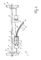
- Fig. 1 shows a first embodiment of the brake cable 1 according to the invention is arranged on an axle unit 2.
- the axle unit consists of an impeller axle 4 and its two outer axles End arranged impeller units 3a and 3b together, each one Impeller and a brake 5a or 5b assigned to it, an impeller unit 3a or 3b form.
- brakes 5a and 5b are shown schematically in FIG shown in simplified form and on the sides facing the center of the axle of the two impellers.
- brakes 5a and 5b e.g. Altenburger brakes, Cantilever brakes, middle pull brakes, disc brakes, V-brakes etc., which can be operated by means of a cable, are used.
- the brake cable 1 includes an actuating cable 6 in the form of a Bowden cable a cable 13a and a sheath 13b, which surrounds the cable 13a, one Brake force distributor 7 and two brake cables 8a and 8b.
- the bottom pull 6 is through a lever 28 which is rotatable on a handle of a vehicle, not shown is arranged, actuated in a known manner, the at one end of the lever 28th attached cable 13a in the direction of rotation indicated by the arrow from the Case 13b is pulled.
- the brake force distributor 7 comprises a fuselage part in the form of a housing 9 with a Recording space 9a and a deflection device in the form of a on a base plate 9b of the housing 9a vertical cylindrical part 10, as in the detailed side view can be seen in section in Fig. 1.
- 1 is the top view Cover plate of the housing not shown.
- the cable 13a of the Bowden cable 6 extends through a first housing passage opening 12a in the receiving space 9a of the housing 9.
- the cable 13 is placed around the cylindrical part 10, so that the cable 13a approximately in opposite the housing through a second housing through opening 12b, but now leaves as a brake cable 8b.
- the brake cable 8b is with connected to the brake 5b and actuates it.
- the housing 9 of the Brake force distributor 7 connected to the brake 5a via the brake cable 8a and operate this.
- the cable 13a is in the position indicated by the broken line is moved by pulling the brake cable 8a in Fig. 1 to the left in the Housing actuated the brake 5b and at the same time the brake force distributor due to the shortening of the cable shifted to the right, which immediately also the brake cable 8a attached to it pulled to the right and consequently the Brake 5a is operated.
- the brake cable 8a is detachable on the housing 9 of the Brake force distributor 7 attached.
- the housing 9 is on the side of the Brake cable 8a with a connecting part receptacle 29 in the form of a laterally open cylindrical recess provided in which a connecting part 30 on which the Brake cable 8a is attached and a cylindrical front part corresponding to the Has connecting part receptacle 29, can be inserted, so that the connecting part receptacle 29 partially the front cylindrical part of the connecting part 30 surrounds a positive connection between the housing 9 and the To produce connecting part 30.
- connection mechanism is used for releasably fastening the brake cable 8b used, however the brake cable is not connected to the housing via a connecting part attached but there are separately a connector receptacle 29 'and Connecting part 30 'is provided, through which the brake cable 8b on the Braking device is releasably attached.
- FIG. 2 shows a second embodiment of the brake cable 1 according to the invention shown.
- the axle unit 2 shown therein, the connection mechanism for releasing the Brake cables 8a and 8b, and the actuating cable 6 correspond to FIG. 1, where the same parts are given the same reference numerals. A description these components can therefore be omitted.
- the brake force distributor 7 shown in FIG. 2 comprises a housing 9 with a Receiving space 9a and a guide part 15 arranged displaceably therein. Furthermore, a housing through opening 11 is formed on the right in the housing 9. The brake cable 8b and the am run through the through opening 11 Brake force distributor 7 incoming Bowden cable 6. The brake cable 8b is with a End attached directly to the guide part 15 and with the other end over the Connecting parts 29 'and 30' attached to the brake 5b.
- a guide passage opening 16 is formed in the middle of the guide part 15, which extends in the direction of the displacement of the guide member 15. Through this Guide passage opening 16 in the guide part 15 runs the cable 13a through and is with its end on the inside of the receiving space 9a or Interior of the housing 9 attached while the casing 13b of the Bowden cable 6 the side of the housing through opening 11 bears against or on the guide part 15 is attached.
- 3a is a third embodiment of the invention Brake cable 1 shown.
- the am Brake force distributor 7 incoming brake cables 8a and 8b and the Bowden cable 6 together with cable 13a and sleeve 13b shown.
- the brake force distributor 7 in FIG. 3a comprises a housing 9 (shown without a cover), which has an oval shape, a V-shaped rotating part 17, which consists of a first and a second leg 22a and 22b, and a first and a second Sliding element 18a and 18b.
- the first and the second displacement element 18a and 18b each have an elongated hole guide 24a and 24b.
- Through the Slotted hole guide 24a of the first, shorter, displacement element 18a on the left in FIG. 3a extends an integrally formed with the rear wall of the housing Guide sleeve 25a and through the slot guide 24b of the second, longer, in 3a right shift element 18b extend two, also in one piece with the housing rear wall formed guide sleeves 25b and 25c.
- the displacement elements 18a and 18b are each in the form of an elongated part formed and each have an end with a through hole for attachment a brake cable and an opposite one, pointed to one side tapering end. In addition, is at the tip end of the longer sliding element 18b, one of which protrudes approximately vertically upwards, also tapering Leg 19 formed. Both displacement elements 18a and 18b are each with their pointed ends rotatably attached to the V-shaped rotating part 17, the second Sliding element 18b a through opening 20 in the tapered front Has part through which a leg 22a of the V-shaped rotating part 17th extends.
- the two displacement elements 18a and 18b are on a horizontal line arranged and the end faces of the mutually facing pointed ends are arranged parallel to each other and from each other in the non-actuated state spaced.
- the legs 22a and 22b of the V-shaped rotating part 17 are each flat, themselves tapered plates, whereas the displacement elements 18a and 18b are bar-shaped are formed with a wider and a narrower side.
- the compound Condition is the flat side of the V-shaped rotating part 17 and the wider sides of the displacement elements 18a and 18b parallel to each other.
- Fig. 3a is the originally tapered connection area of the two Legs 22a and 22b of the V-shaped rotating part 17 are cut.
- the displacement elements 18a and 18b are at their tips on the first and second Legs 22a and 22b of the V-shaped rotating part 17 in the connection area of the two legs 22a and 22b rotatably attached.
- a Bowden cable 6 with a cable 13a and a sleeve 13b leads through one Through opening in the housing into the interior of the housing.
- the cable 13a extends through a through opening 19a in the outer end of the tapered leg 19 of the second displacement element 18b.
- a cable 13a of the Bowden cable 6 is attached at the free end of the first leg 22a of the V-shaped rotating part 17, which extends through the longer connecting element 18b extends.
- the envelope 13b of the Bowden cable 6 is supported in relation to the second displacement element 18b Range of the vertically projecting leg 19 from.
- Fig. 3b is the brake force distributor 7 in Fig. 3a with the housing closed and foot pedal 23 arranged thereon shown.
- the foot pedal in Fig. 3b Actuating leg 22c of the V-shaped rotating part 17 moved into the housing 9, so that the V-shaped rotating member 17 is rotated counterclockwise and consequently the fastening points with the two connecting elements 18a and 18b with respect to an imaginary pivot point of the V-shaped rotating part 17 in opposite transverse directions are moved towards each other and over the Brake cables 8a and 8b actuate the brakes (not shown).
- FIG. 4a shows the first embodiment described with reference to FIG Foot pedal.
- the brake booster 7 is on the side of the housing 9 which the cable 13a and the brake cable 8b lead into or out of the housing 9
- Operating rotary part 26 is arranged, which with respect to the longitudinal axis of the housing 9 is rotatable.
- the rotary actuator 26 has three cylindrically shaped sections 26 ', 26 "and 26"', the first section 26 'seen from the right in FIG. 4a has a diameter approximately equal to the width of the housing 9, the second Section 26 "has the smallest diameter and the third section 26" 'one Has diameter between the first and third sections 26 'and 26 "'.
- the opening 31 "of the recess 31 a Has diameter corresponding to the second section 26 "and the recess 31st a wider holding section 31 '"with a diameter corresponding to the third has cylindrical portion 26 "'of the rotary actuator 26.
- a foot pedal 23 is attached, through which the operating rotary part of can be rotated by an operator.
- through openings 32a and 32b are provided, wherein the through hole 32a is at an arc angle of approximately 90 ° extending slot opening through which the brake cable 8b extends, and the through opening 32b is a round hole through which the cable pull 13a extends.
- Fig. 4b the foot pedal 23 and the operating rotary member 26 are each in one Operating position (solid line) and in a non-operating position (dashed line) is shown.
- the cable 13a is transverse to it Longitudinal course corresponding to the path of the through opening 32b taken so that the cable is pulled out of the housing in Fig. 4a and consequently, braking, as already described with reference to FIG. 1, takes place.
Landscapes
- Engineering & Computer Science (AREA)
- Transportation (AREA)
- Mechanical Engineering (AREA)
- Braking Arrangements (AREA)
- Transmission Of Braking Force In Braking Systems (AREA)
Abstract
Description
- Fig. 1:
- eine Ansicht von oben teilweise im Schnitt einer ersten Ausführungsform des erfindungsgemäßen Bremszuges;
- Fig. 2:
- eine Ansicht von oben teilweise im Schnitt einer zweiten Ausführungsform des erfindungsgemäßen Bremszuges;
- Fig. 3a
- eine perspektivische Vorderansicht einer dritten Ausführungsform des erfindungsgemäßen Bremszuges;
- Fig. 3b
- eine perspektivische Vorderansicht des Bremszugs in Fig. 3a mit einem Fußpedal;
- Fig. 4a
- eine Ansicht von oben teilweise im Schnitt des Bremskraftverteilers in Fig. 1 mit einem Fußpedal; und
- Fig. 4b
- eine Seitenansicht des Fußpedals in Fig. 4a.
- 1
- Bremszug
- 2
- Achseinheit
- 3a, 3b
- Laufradeinheiten
- 4
- Laufradachse
- 5a, 5b
- Bremsen
- 6
- Betätigungsseilzug
- 7
- Bremskraftverteiler
- 8a, 8b
- Bremsseile
- 9
- Gehäuse
- 10
- Umlenkeinrichtung
- 12a, 12b
- Gehäuse-Durchgangsöffnungen
- 13a
- Seilzug
- 13b
- Hülle
- 14
- Gehäuse-Durchgangsöffnung
- 15
- Führungsteil
- 16
- Führungs-Durchgangsöffnung
- 17
- Drehteil
- 18a, 18b
- erstes und zweite Verschiebeelement
- 19
- senkrecht abstehendes Teil
- 20
- Durchgangsöffnung
- 21 a, 21 b
- Durchgangsöffnungen
- 22a, 22b
- erster und zweiter Schenkel
- 22c
- Betätigungsschenkel
- 23
- Fußpedal
- 24a, 24b
- Langlochführungen
- 25a, b, c
- Führungshülsen
- 26
- Betätigungs-Drehteil
- 27
- Mitnehmer-Durchgangsöffnung
Claims (36)
- Bremszug (1) für eine Achseinheit (2) mit zwei Laufradeinheiten (3a, 3b), die an einer Laufradachse (4) angeordnet sind, wobei jede der Laufradeinheiten (3) über wenigstens eine eigene Bremse (5a, 5b) verfügt, die durch einen Betätigungsseilzug (6) betätigbar ist,
dadurch gekennzeichnet, dass
die jeweils den Laufradeinheiten (3a, 3b) zugeordneten Bremsen (5a, 5b) durch Betätigen eines einzigen Betätigungsseilszuges (6) betätigbar sind. - Bremszug (1 ) nach Anspruch 1,
dadurch gekennzeichnet, dass
die jeweils den Laufradeinheiten (3a, 3b) zugeordneten Bremsen (5) gleichzeitig betätigbar sind. - Bremszug (1) nach Anspruch 1 oder 2,
dadurch gekennzeichnet, dass
die jeweils den Laufradeinheiten (3a, 3b) zugeordneten Bremsen (5a, 5b) dieselbe Bremskraft an den jeweiligen Laufrädern entfalten. - Bremszug (1) nach einem der vorhergehenden Ansprüche,
dadurch gekennzeichnet, dass
ein Bremskraftverteiler (7), insbesondere am dem Betätigungsende abgewandten Ende des Betätigungsseilzuges (6), vorgesehen ist, durch den die von einem Bediener auf den Betätigungsseilzug (6) aufgebrachte Zugkraft auf wenigstens zwei, den Laufradeinheiten (3a, 3b) zugeordneten Bremsseilen (8a, 8b) verteilt wird. - Bremszug (1) nach einem der vorhergehenden Ansprüche,
dadurch gekennzeichnet, dass
der Betätigungsseilzug (6) ein Bowdenzug ist. - Bremszug (1) nach Anspruch 4,
dadurch gekennzeichnet, dass
durch den Bremskraftverteiler (7) beim Betätigen des Betätigungsseilzugs (6) dessen Zugbewegung in zwei gegenläufige Zugbewegungen der wenigstens zwei Bremsseile (8), insbesondere parallel zur Laufradachse (4), umgesetzt wird. - Bremszug (1) nach einem der vorhergehenden Ansprüche,
dadurch gekennzeichnet, dass
die wenigstens zwei Bremsseile (8) parallel zur Laufradachse (4) verlaufen. - Bremszug (1) nach einem der Ansprüche 4 bis 7,
dadurch gekennzeichnet, dass
der Bremskraftverteiler (7) an der Laufradachse (4), insbesondere in etwa mittig zwischen den beiden Laufradeinheiten (3a, 3b), angeordnet ist. - Bremszug (1) nach einem der Ansprüche 4 bis 8,
dadurch gekennzeichnet, dass
der Bremskraftverteiler (7) ein Gehäuse (9), insbesondere ein kastenähnliches oder zylindrisches oder ovales Gehäuse aufweist. - Bremszug (1) nach einem der vorhergehenden Ansprüche,
dadurch gekennzeichnet, dass
der Bremskraftverteiler (7) eine Umlenkeinrichtung (10) aufweist, durch die der ankommende Betätigungsseilzug (6) umgelenkt wird und mit seinem vom Bremskraftverteiler (7) ausgehenden Ende, insbesondere das dem Betätigungsende des Betätigungsseilzuges (6) gegenüberliegende Ende, zum Betätigen einer ersten Laufradeinheit (3a) zugeordneten Bremse (5a) daran befestigt ist. - Bremszug (1) nach Anspruch 10,
dadurch gekennzeichnet, dass
zwischen dem Bremskraftverteiler (7) und der einer zweiten Laufradeinheit (3b) zugeordneten Bremse (5b) ein Verstellelement (11) angeordnet ist, insbesondere daran befestigt ist, durch welches die Bremse (5b) der zweiten Laufradeinheit (3b) betätigbar ist. - Bremszug (1) nach Anspruch 11,
dadurch gekennzeichnet, dass
das Verstellelement (11) eine Verstellstange ist. - Bremszug (1) nach Anspruch 11,
dadurch gekennzeichnet, dass
das Verstellelement (11) ein Bremsseil ist. - Bremszug (1) nach einem der Ansprüche 10 bis 13,
dadurch gekennzeichnet, dass
auf der der ersten Laufradeinheit (3a) zugeordneten Seite des Bremskraftverteilers (7) wenigstens eine, insbesondere zwei Durchgangsöffnungen (12a, 12b) am Gehäuse (9) des Bremskraftverteilers (7) vorgesehen sind, durch welche(s) jeweils der ankommende und der ausgehende Betätigungsseilzug (6) hindurch verläuft. - Bremszug (1) nach einem der Ansprüche 10 bis 14,
dadurch gekennzeichnet, dass
die Umlenkeinrichtung (10) eine Umlenkrolle ist. - Bremszug (1) nach einem der Ansprüche 10 oder 14,
dadurch gekennzeichnet, dass
die Umlenkeinrichtung (10) ein feststehendes, insbesondere ein mit dem Gehäuse (9) der Umlenkeinrichtung (10) einstückig ausgebildetes Teil mit einer zylindrischen Außenfläche ist. - Bremszug (1 ) nach einem der Ansprüche 10 bis 16,
dadurch gekennzeichnet, dass
sich die Hülle (13) des am Bremskraftverteilers (7) ankommenden Bowdenzugs (6) an der Außenseite des Gehäuses (9) des Bremskraftverteilers (7) abstützt. - Bremszug (1) nach einem der Ansprüche 10 bis 17,
dadurch gekennzeichnet, dass
durch Verschieben des Betätigungsseilzuges (6) in Richtung weg vom Bremskraftverteiler (7) die der ersten Laufradeinheit (3a) zugeordnete Bremse (5a), an welcher der Betätigungsseilzug (6) befestigt ist, betätigt und gleichzeitig der gesamte Bremskraftverteiler (7) samt des an ihm befestigten Vertellelements (11) in Richtung zur ersten Laufradeinheit (3a) verschoben wird, so dass gleichzeitig durch diese Verschiebung die der zweiten Laufradeinheit (b) zugeordnete Bremse betätigt (5b) wird. - Bremszug (1) nach einem der Ansprüche 1 bis 9,
dadurch gekennzeichnet, dass
an der der ersten Laufradeinheit (3a) zugewandten Seite des Gehäuses (9) des Bremskraftverteilers (7) eine Gehäuse-Durchgangsöffnung (14) gebildet ist. - Bremszug (1) nach Anspruch 19,
dadurch gekennzeichnet, dass
im Inneren des Gehäuses (9) ein in Längsrichtung des Innenraums des Gehäuses (9) verschiebbares Führungsteil (15) angeordnet ist, welches eine Durchgangsöffnung (16) aufweist, die mit der Gehäuse-Durchgangsöffnung (14) fluchtet. - Bremszug (1) nach Anspruch 20,
dadurch gekennzeichnet, dass
der Betätigungsseilzug (6) ein Bowdenzug mit einem Seilzug (13a) und einer Hülle (13b) ist, wobei sich der Seilzug (13a) durch die Gehäuse-Durchgangsöffnung (14) und durch die Durchgangsöffnung (16) im Führungsteil (15) erstreckt und an der Innenseite des Gehäuses (9) befestigt ist. - Bremszug (1) nach Anspruch 21,
dadurch gekennzeichnet, dass
sich die Hülle (13b) des Bowdenzugs durch die Gehäuse-Durchgangsöffnung (14) erstreckt und sich am verschiebbaren Führungsteil (15) abstützt. - Bremszug (1) nach einem Ansprüche 19 bis 22,
dadurch gekennzeichnet, dass
ein erstes Bremsseil (17a) vorgesehen ist, das sich durch die Gehäuse-Durchgangsöffnung (14) oder eine separat vorgesehene Durchgangsöffnung (14') erstreckt, wobei ein Ende des ersten Bremsseils (17a) am Führungsteil (15) befestigt ist und das gegenüberliegende Ende des ersten Bremsseils (17a) an der der einer ersten Laufradeinheit (3a) zugeordneten Bremse (5a) befestigt ist. - Bremszug (1) nach einem der Ansprüche 19 bis 23,
dadurch gekennzeichnet, dass
ein zweites Bremsseil (17b) vorgesehen ist, das mit einem Ende an der der Gehäuse-Durchgangsöffnung (14) gegenüberliegenden Seite außen am Gehäuse (9) befestigt ist und mit dem anderen Ende der einer zweiten Laufradeinheit (3b) zugeordneten Bremse (5b) befestigt ist. - Bremszug (1) nach Anspruch 24,
dadurch gekennzeichnet, dass
durch des Verschieben der Betätigungsseilzuges (6) das Gehäuse (9) des Bremskraftverteilers (7) in Richtung zur Hülle (13b) des Bowdenzuges verschoben wird, so dass sich das Führungsteil (15) samt dem an ihm befestigten ersten Bremsseil (17a) relativ zum Gehäuse (9) in Richtung zur der der Gehäuse-Durchgangsöffnung (14) gegenüberliegenden Innenseite des Gehäuses (9) verschiebt, wodurch die Gesamtlänge von erstem Bremsseil (17a), zweitem Bremsseil (17b) und Bremskraftverteiler (7) verkürzt und folglich beide den Laufradeinheiten (3a, 3b) zugeordneten Bremsen (5a, 5b) gleichzeitig betätigt werden. - Bremszug (1) nach einem der Ansprüche 1 bis 9,
dadurch gekennzeichnet, dass
im Inneren des Gehäuses (9) des Bremskraftverteilers (7) ein um eine Drehachse (18) drehbar gelagertes Drehelement (19) vorgesehen ist. - Bremszug (1) nach Anspruch 26,
dadurch gekennzeichnet, dass
die beiden Bremsseile (17a, 17b) an Stellen auf dem Drehelement (19) befestigt sind, die sich bezüglich der Drehachse (18) jeweils auf gegenüberliegenden Seiten am Drehelement (19) befinden, und der Betätigungsseilzug (6) an einer Stelle am Drehelement (19) befestigt ist, die weiter von der Drehachse (18) beabstandet ist als die Stellen, an denen die Bremsseile (17a, 17b) befestigt sind. - Bremszug (1) nach Anspruch 27,
dadurch gekennzeichnet, dass
im Gehäuse (9) eine Durchgangsöffnung (20) vorgesehen ist, durch welche sich der Betätigungsseilzug (6) in das Gehäuse (9) erstreckt, und jeweils auf den den Laufradeinheiten (3a, 3b) zugewandten Seiten des Gehäuses (9) jeweils eine Durchgangsöffnung (21a, 21b) zum Durchführen der Bremsseile (17a, 17b) vorgesehen ist. - Bremszug (1) nach einem der Ansprüche 26 bis 28,
dadurch gekennzeichnet, dass
das Drehelement (19) eine drehbar gelagerte Stange ist. - Bremszug (1) nach einem der Ansprüche 26 bis 28
dadurch gekennzeichnet, dass
das Drehelement (19) eine drehbar gelagerte Scheibe ist. - Bremszug (1) nach einem der Ansprüche 26 bis 28,
dadurch gekennzeichnet, dass
das Drehelement (19) ein V-förmiger Bügel mit einem ersten und einem zweiten Schenkel (22a, 22b) ist. - Bremszug (1) nach Anspruch 31,
dadurch gekennzeichnet, dass
an einem äußeren Ende des V-Bügels ein weiterer Schenkel (22c) ausgebildet ist, der sich vom Inneren des Gehäuses (9) nach außerhalb des Gehäuses (9) erstreckt und zum Betätigen mittels einer Fußpedalvorrichtung (23) vorgesehen ist. - Bremszug (1) nach Anspruch 26 bis 32,
dadurch gekennzeichnet, dass
zwei Verbindungselemente (23a, 23b) vorgesehen sind, die sich vom Gehäuseinneren nach außerhalb des Gehäuses (9) durch Durchgangsöffnungen (21a, 21 b) im Gehäuse (9) erstrecken und jeweils mit einem Ende am V-Bügel drehbar befestigt sind und am jeweils anderen Ende ein Bremsseil (17a, 17b) befestigt ist. - Bremszug (1) nach Anspruch 33,
dadurch gekennzeichnet, dass
die Verbindungselemente (23a, 23b) jeweils eine Langlochführung (24a, 24b) aufweisen, durch welche sich Führungsbolzen (25), die senkrecht zur Drehebene des Drehelements (18) gebildet sind, erstrecken. - Bremszug (1) nach einem der Ansprüche 4 bis 34,
dadurch gekennzeichnet, dass
ein Betätigungs-Drehteil (26) am Bremskraftverteiler (7) vorgesehen ist, das um eine Drehachse parallel zum Betätigungsseilzug (6) bezüglich des Bremskraftverteilers (7) drehbar gelagert ist, mit einer Mitnehmer-Durchgangsöffnung (27) zum Durchführen des ankommenden Betätigungsseilzugs (6), welche bei Drehung des Betätigungs-Drehteils (26) den Betätigungsseilzug (6) in Drehrichtung mitnimmt - Bremszug (1) nach Anspruch 35,
dadurch gekennzeichnet, dass
am Betätigungs-Drehteil (26) eine Fußpedalvorrichtung (23) vorgesehen ist, durch welche das Betätigungs-Drehteil (26) von einem Bediener zur Betätigung des Betätigungsseilzugs (6) in Drehung versetzt werden kann.
Applications Claiming Priority (4)
| Application Number | Priority Date | Filing Date | Title |
|---|---|---|---|
| DE20309407 | 2003-06-07 | ||
| DE20309407U | 2003-06-07 | ||
| DE20318719U DE20318719U1 (de) | 2003-06-07 | 2003-12-03 | Bremszug |
| DE20318719U | 2003-12-03 |
Publications (2)
| Publication Number | Publication Date |
|---|---|
| EP1484230A2 true EP1484230A2 (de) | 2004-12-08 |
| EP1484230A3 EP1484230A3 (de) | 2007-09-26 |
Family
ID=33160879
Family Applications (1)
| Application Number | Title | Priority Date | Filing Date |
|---|---|---|---|
| EP04013411A Withdrawn EP1484230A3 (de) | 2003-06-07 | 2004-06-07 | Mit Bremszügen betätigbare Bremseinrichtung |
Country Status (1)
| Country | Link |
|---|---|
| EP (1) | EP1484230A3 (de) |
Family Cites Families (4)
| Publication number | Priority date | Publication date | Assignee | Title |
|---|---|---|---|---|
| DE2454240A1 (de) * | 1974-11-15 | 1976-05-20 | Daimler Benz Ag | Hand- oder fussfeststell-bremse mit einem bowdenzug, insbesondere fuer kraftfahrzeuge |
| IT8253196V0 (it) * | 1982-04-16 | 1982-04-16 | Fiat Auto Spa | Dispositivo di comando con trasmissione a cavo flessibile per il freno di stazionamento di autoveicoli |
| US5983745A (en) * | 1997-04-28 | 1999-11-16 | Petrak; Gregory H. | Park brake cable system including connector clip and associated method of tensioning |
| FR2843349B1 (fr) * | 2002-08-07 | 2004-10-01 | Kwang Yang Motor Co | Dispositif de freinage pour vehicule tous terrains |
-
2004
- 2004-06-07 EP EP04013411A patent/EP1484230A3/de not_active Withdrawn
Non-Patent Citations (1)
| Title |
|---|
| None |
Also Published As
| Publication number | Publication date |
|---|---|
| EP1484230A3 (de) | 2007-09-26 |
Similar Documents
| Publication | Publication Date | Title |
|---|---|---|
| DE3610789C2 (de) | ||
| DE102005058428A1 (de) | Stoßdämpfende Vorrichtung für Bremspedale | |
| DE2653846A1 (de) | Fahrrad-felgenbremse | |
| DE69933387T2 (de) | Handbremse | |
| EP3107774A1 (de) | Betätigungsvorrichtung für eine feststellbremse | |
| DE2429665B2 (de) | Blockiervorrichtung für ein Motorfahrzeug | |
| DE20009720U1 (de) | Hydraulisches Fahrradbremssystem | |
| DE2454240A1 (de) | Hand- oder fussfeststell-bremse mit einem bowdenzug, insbesondere fuer kraftfahrzeuge | |
| DE2324871B2 (de) | Handbremse fuer ein kraftfahrzeug | |
| DE2360856A1 (de) | Vorrichtung zur axialen verschiebung eines bremskabels | |
| EP1484230A2 (de) | Mit Bremszügen betätigbare Bremseinrichtung | |
| DE102014017997A1 (de) | Fahrradsteuervorrichtung | |
| DE2527745C3 (de) | Bremsgestänge für Kraftfahrzeuge oder Anhänger | |
| DE1958956C3 (de) | Fahrtrichtungsanzeigeschalter mit selbsttätiger Rückstellung durch die Lenkeinrichtung | |
| DE20318719U1 (de) | Bremszug | |
| DE3518992C2 (de) | ||
| DE1803891B2 (de) | Drehgriff fuer fahrraeder mit hilfsmotor | |
| DE2309320C3 (de) | Starres Schiebedach für Fahrzeuge mit in Schieberichtung beweglichen Bremsstangen | |
| DE19617065C1 (de) | Zugvorrichtung für Fahrzeuganhänger | |
| DE202009014521U1 (de) | Bremsvorrichtung für Handwagen mit drei oder mehr Rädern, wie z.B. Golftaschenwagen, Kinderwagen u.dgl. | |
| DE715894C (de) | Mechanischer Bremsausgleich fuer Bremsgestaenge von Fahrzeugen | |
| DE1455983C3 (de) | Teilbelagscheibenbremse für Kraftfahrzeuge | |
| DE2362220A1 (de) | Bremsanlage, insbesondere fuer einen ackerschlepper | |
| DE935345C (de) | Vorrichtung zum Lenken von Raupenschleppern | |
| DE3234336C2 (de) |
Legal Events
| Date | Code | Title | Description |
|---|---|---|---|
| PUAI | Public reference made under article 153(3) epc to a published international application that has entered the european phase |
Free format text: ORIGINAL CODE: 0009012 |
|
| AK | Designated contracting states |
Kind code of ref document: A2 Designated state(s): AT BE BG CH CY CZ DE DK EE ES FI FR GB GR HU IE IT LI LU MC NL PL PT RO SE SI SK TR |
|
| AX | Request for extension of the european patent |
Extension state: AL HR LT LV MK |
|
| PUAL | Search report despatched |
Free format text: ORIGINAL CODE: 0009013 |
|
| AK | Designated contracting states |
Kind code of ref document: A3 Designated state(s): AT BE BG CH CY CZ DE DK EE ES FI FR GB GR HU IE IT LI LU MC NL PL PT RO SE SI SK TR |
|
| AX | Request for extension of the european patent |
Extension state: AL HR LT LV MK |
|
| AKX | Designation fees paid | ||
| STAA | Information on the status of an ep patent application or granted ep patent |
Free format text: STATUS: THE APPLICATION IS DEEMED TO BE WITHDRAWN |
|
| 18D | Application deemed to be withdrawn |
Effective date: 20080327 |
|
| REG | Reference to a national code |
Ref country code: DE Ref legal event code: 8566 |