EP1484029A2 - Orthodontisches Bracket und damit zusammenpassende Beleuchtungsanordnung zum Polymerisieren - Google Patents
Orthodontisches Bracket und damit zusammenpassende Beleuchtungsanordnung zum Polymerisieren Download PDFInfo
- Publication number
- EP1484029A2 EP1484029A2 EP04019175A EP04019175A EP1484029A2 EP 1484029 A2 EP1484029 A2 EP 1484029A2 EP 04019175 A EP04019175 A EP 04019175A EP 04019175 A EP04019175 A EP 04019175A EP 1484029 A2 EP1484029 A2 EP 1484029A2
- Authority
- EP
- European Patent Office
- Prior art keywords
- bracket
- housing
- light assembly
- curing light
- adhesive
- Prior art date
- Legal status (The legal status is an assumption and is not a legal conclusion. Google has not performed a legal analysis and makes no representation as to the accuracy of the status listed.)
- Withdrawn
Links
Images


Classifications
-
- A—HUMAN NECESSITIES
- A61—MEDICAL OR VETERINARY SCIENCE; HYGIENE
- A61C—DENTISTRY; APPARATUS OR METHODS FOR ORAL OR DENTAL HYGIENE
- A61C19/00—Dental auxiliary appliances
- A61C19/003—Apparatus for curing resins by radiation
- A61C19/004—Hand-held apparatus, e.g. guns
-
- A—HUMAN NECESSITIES
- A61—MEDICAL OR VETERINARY SCIENCE; HYGIENE
- A61C—DENTISTRY; APPARATUS OR METHODS FOR ORAL OR DENTAL HYGIENE
- A61C7/00—Orthodontics, i.e. obtaining or maintaining the desired position of teeth, e.g. by straightening, evening, regulating, separating, or by correcting malocclusions
- A61C7/12—Brackets; Arch wires; Combinations thereof; Accessories therefor
- A61C7/14—Brackets; Fixing brackets to teeth
- A61C7/16—Brackets; Fixing brackets to teeth specially adapted to be cemented to teeth
-
- A—HUMAN NECESSITIES
- A61—MEDICAL OR VETERINARY SCIENCE; HYGIENE
- A61C—DENTISTRY; APPARATUS OR METHODS FOR ORAL OR DENTAL HYGIENE
- A61C7/00—Orthodontics, i.e. obtaining or maintaining the desired position of teeth, e.g. by straightening, evening, regulating, separating, or by correcting malocclusions
- A61C7/12—Brackets; Arch wires; Combinations thereof; Accessories therefor
- A61C7/14—Brackets; Fixing brackets to teeth
- A61C7/146—Positioning or placement of brackets; Tools therefor
Definitions
- This invention relates to an improved orthodontic bracket and light curing assembly that together provide enhanced bond strength between the bracket and the tooth and especially beneath a central portion of the bracket base.
- Orthodontic treatment involves movement of the teeth toward desired positions for correct occlusion.
- tiny slotted orthodontic appliances known as brackets are connected to the teeth, and an archwire is placed in the slot of each bracket.
- the archwire forms a track to guide movement of the teeth to orthodontically correct positions.
- Brackets are adapted to be directly bonded to the surface of the patient's teeth by means of an orthodontic bonding adhesive.
- Some adhesives such as CONCISE brand adhesive (from 3M Unitek) are supplied as two initially separate components that, once mixed together, are self-curing. Such two-component adhesives, however, have only a limited "working time" during which the orthodontist can transfer the adhesive to the bracket base, place the bracket on the tooth and shift the bracket to a particular desired position on the tooth before the adhesive begins to harden.
- TRANSBOND brand adhesive also from 3M Unitek
- TRANSBOND brand adhesive also from 3M Unitek
- Light-curable adhesives are preferred by many orthodontists because the length of the "working time" can be chosen as needed.
- the bracket can be carefully placed on the patient's tooth and shifted as desired until the orthodontist is satisfied with the position of the bracket.
- the adhesive does not harden until a source of light is directed toward the adhesive.
- brackets for example, have an outer base surface that is roughened, scribed or dimpled, while other brackets have a base surface that includes one or more layers of irregularly-shaped fragments or spherical particles. Such base surfaces present an increased surface area available for contact with the adhesive in order to improve the strength of the bond between the bracket and the tooth.
- brackets have bases that present undercut regions. Undercuts in the base enable the adhesive, once hardened, to form a mechanical interlock with the bracket. For example, the irregularly-shaped fragments or spherical particles mentioned above may present undercut regions. As another example, the bases of some brackets have a fine mesh metal "screen", or pad that provides a mechanical interlock when embedded into cured adhesive. Other brackets, such as that shown in U.S. Design Patent No. 290,040, have a series of undercut grooves that provide a mechanical interlock with hardened adhesive. U.S. Patent Nos. 4,094,068 and 5,435,720 describe brackets having bases with peripheral holes or notches that enable the adhesive to flow through and produce an enlarged head that serves to improve retention of the bracket on the tooth.
- the bond may not have sufficient strength to retain the bracket on the tooth when the bracket is subjected to relatively large forces, as when the patient bites into a relatively hard food object.
- the bracket may debond from forces exerted by the archwire, by orthodontic auxiliaries or by attachments coupled to the bracket. Premature debonding of orthodontic brackets represents a nuisance to both the orthodontist and the patient that is best avoided, since the patient normally must return to the orthodontist for rebonding of the detached bracket or replacement with a new bracket in order to resume treatment.
- bracket bonding procedures Another difficulty that is sometimes encountered in orthodontic bracket bonding procedures pertains to removal of excess adhesive following placement of the bracket but prior to the time that the adhesive has hardened.
- the bracket In many bonding procedures, the bracket is carefully positioned in a selected location and then pressure is applied to the bracket to firmly seat the bracket in the adhesive.
- the orthodontist will choose to apply an excess amount of adhesive to the bracket base prior to seating to insure that the entire surface of the bracket base is in contact with adhesive and to reduce the possibility of air bubbles or voids between the bracket and the tooth where adhesive is not present.
- the excess adhesive is extruded from beneath the bracket base and onto areas of the patient's tooth adjacent the periphery of the bracket base.
- a dental explorer or other tool is then used to pick up and remove the extruded adhesive from the tooth's surface.
- bracket and adhesive typically involves removal of the bracket and adhesive from the tooth, placing an additional quantity of adhesive on the bracket base, repositioning and reseating the bracket on the tooth and removal of the newly extruded adhesive, a procedure that is somewhat time-consuming at best.
- the present invention overcomes the problems noted above in connection with conventional brackets, light-curing units and procedures by provision of improved methods and apparatus for bonding a portion of the adhesive that is directly between a central portion of the bracket base and the patient's tooth.
- the methods and apparatus as described herein may be advantageously used to temporarily secure the bracket to the tooth without curing of the adhesive that has been extruded from peripheral edges of the bracket base during seating of the bracket.
- the excess, extruded adhesive can be easily removed with a dental explorer or other tool and yet the cured portion of the adhesive will prevent movement of the bracket even when unintentionally bumped by the explorer.
- the curing unit can be used to cure portions of the adhesive between peripheral edges of the bracket base and the tooth in order to increase the strength of the adhesive bond to a value useful for orthodontic treatment.
- the invention in one aspect concerns the combination of an orthodontic bracket and a curing light assembly.
- the combination includes an orthodontic bracket having a base with an outer surface for direct bonding to a tooth, wherein the base includes a central portion with at least one opening.
- the bracket also includes a body extending from the base in a direction away from the outer surface.
- the bracket also includes at least one tiewing extending outwardly from a body, and the slot next to the tiewing(s) for receiving an archwire.
- the body includes a central section having a passage aligned with the opening(s) of the base.
- the combination also includes a curing light assembly having a housing with an outer end portion of a size sufficient for reception in the passage of the bracket body.
- the curing light assembly includes a source of light connected to the housing for emitting light from the outer end portion in order to cure bonding adhesive in contact with the central portion of the bracket base when the outer end portion of the housing is received in the passage.
- an orthodontic bracket that comprises a base having an outer surface for direct bonding to a tooth, wherein the base includes a central portion with at least one opening.
- the bracket also includes a body extending from the base in a direction away from the outer surface.
- the body includes a central section having a passage.
- At least one tiewing extends outwardly from the body, and a slot is next to the tiewing(s) for receiving an archwire.
- the body includes a passage that is aligned with the opening(s) of the base for receiving a source of light to cure light-curable bonding adhesive in contact with the central portion of the base.
- the invention also relates to an orthodontic curing light assembly that comprises a housing with an outer end portion and a source of light connected to the housing.
- the source of light is operable to emit light in a direction away from the outer end portion.
- the assembly also includes a coupler for detachably connecting the outer end portion to an orthodontic bracket.
- the invention is particularly advantageous when used in connection with brackets made of an opaque material such as stainless steel or other metals, since the passage in the bracket permits light to reach adhesive beneath a central portion of the bracket base that would otherwise remain substantially uncured. Bond strength between the bracket and the tooth is increased as a result, and the likelihood of unintentional, spontaneous debonding of the bracket during the course of treatment is significantly reduced.
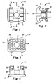
- an orthodontic bracket constructed in accordance with the principles of the present invention is designated broadly by the numeral 20 in Figs. 1-4 and 6-11.
- the bracket 20 includes a base 22 having an outer surface with a certain concave shape that is adapted for direct bonding to a particular tooth.
- the concave shape has a compound contour that matches the convex outer surface of the tooth.
- the base 22 includes a central portion having a circular opening 24 (Figs. 2-3). Additionally, the base 22 includes a series of upstanding pegs 26 that surround the opening 24. Although not shown in detail in the drawings, the pegs 26 preferably have outer ends that are peened over during a tumbling process to present mushroom-shaped heads that establish a mechanical interlock with an orthodontic bonding adhesive once the adhesive has hardened.
- the bracket 20 also includes a body 28 that extends from the base 22 in a direction away from the outer surface of the base 22.
- the mesial-distal length of the body 28 i.e., in a direction extending between mesial and distal sides of the body 28
- the mesial-distal length of the body 28 is less than the mesial-distal length of the base 22.
- the occlusal-gingival height of the body 28 i.e., in a direction between occlusal and gingival sides of the body 28
- the occlusal-gingival height of the base 22 is less than the occlusal-gingival height of the base 22.
- the bracket 20 also includes a pair of spaced apart occlusal tiewings 30 that extend away from the body 28 in a buccal-labial direction (i.e., in a direction toward the patient's lips or cheeks) as well as in an occlusal direction (i.e., in a direction toward the outer ends or tips of the patient's teeth).
- the bracket 20 includes two spaced apart gingival tiewings 32 that extend in a buccal-labial direction as well as in a gingival direction (i.e., in a direction toward the patient's gums or gingiva).
- the tiewings 30, 32 are integrally connected to the body 28, which in turn is preferably integrally interconnected to the base 22.
- An archwire slot 34 extends in a generally mesial-distal direction across the bracket 20.
- the archwire slot 34 is comprised of a mesial slot portion located between the occlusal tiewing 30 and the gingival tiewing 32 which are connected to a mesial side of the body 28, and a distal slot portion located between the occlusal tiewing 30 and the gingival tiewing 32 which are connected to the distal side of the body 28.
- the bottom of the archwire slot 34 i.e., the wall of the archwire slot 34 that is closest to the base 22 of the bracket 20
- the body 28 includes a central section located between the mesial side of the body 28 (which is connected to the mesial pair of tiewings 30, 32) and the distal side of the body 28 (which is connected to the distal pair of tiewings 30, 32).
- the central section of the body 28 includes an enclosed, central passage 36 that is open on both ends and preferably has a cylindrical sidewall:
- the passage 36 extends from the buccal-labial side of the body 28 to the lingual side of the body 28 (i.e., in a direction toward the patient's cheeks) and is aligned with the circular opening 24 of the bracket base 22.
- the passage 36 is aligned with the opening 24 in both an occlusal-gingival direction and a mesial-distal direction, and in the embodiment shown the circular opening 24 has the same diameter and is located at the lingual end of the passage 36.
- the central axis of the passage 36 when extended, passes through the archwire slot 34 and preferably passes through the middle of the archwire slot 34 when considered in an occlusal-gingival direction.
- the central axis of the passage 36 is parallel to the occlusal and gingival walls defining the archwire slot 34.
- a curing light assembly according to another aspect of the invention is broadly designated by the numeral 40 and is shown in Figs. 5 and 7-11.
- the assembly 40 in this embodiment includes a case 42 that contains a portable power source such as a rechargeable battery.
- the case 42 is connected to an elongated housing 44.
- the housing 44 preferably is constructed so that its configuration is repositionable and can be changed to any one of a number of different self-supporting configurations.
- the housing 44 may have a straight longitudinal axis, or be repositioned to have a curved longitudinal axis in any one of a number of different arcs.
- the housing 44 may be constructed by providing an interconnected series of annular sections similar to those used for gooseneck lamps and the like.
- the housing 44 has an outer end portion 46 that contains a source of light.
- the source of light is a solid state light emitter 48 (Fig. 5 only) such as a light emitting diode.
- solid state light emitter means any device that converts electric energy into electromagnetic radiation through the recombination of holes and electrons. Examples of solid state light emitters include semi-conductor light emitting diodes, semi-conductor laser diodes, polymer light emitting diodes and electroluminescent devices (i.e., devices that convert electric energy to light by a solid phosphor subjected to an alternating electric field).
- the outer end portion 46 may comprise a focusing lens for the emitter 48, such as the dome-shaped lens that covers commonly available light emitting diodes.
- the lens preferably is shaped to direct a substantial majority of the light emitted from the emitter in a forward direction that is generally parallel with the longitudinal axis of the housing 44.
- the emitter 48 is connected by a pair of wires (not shown) that extend within the housing 44 to the battery power source within the case 42.
- a spring-loaded finger switch 50 is movably connected to the case 42 and is electrically connected to one of the wires extending between the emitter 48 and the power source. When the switch 50 is depressed, the switch 50 closes the circuit and enables the emitter 48 to receive current from the power source.
- the outer end portion 46 is of a size sufficiently small to fit within the confines of the passage 36.
- the diameter of the hemisphere is 0.03 inch (0.75mm).
- the hemisphere has a diameter that is preferably just slightly less than the diameter of the passage 36.
- the outer end portion 46 is provided with a means for readily detaching from any orthodontic adhesive that it contacts.
- a means for readily detaching from any orthodontic adhesive that it contacts could comprise, for example, a release coating, such as a silicone polymer or a hard coating similar to coatings used for coating eyeglass lenses.
- the curing light assembly also includes at least one tab 52 that is coupled to the housing 44.
- a pair of tabs 52 are provided and extend outwardly in opposite directions away from each other as well as from the housing 44.
- the tabs 52 are connected to a central cylindrical member that is located directly adjacent the outer end portion 46.
- the housing 44 extends through a bore that passes through the center of the cylindrical member.
- the tabs 52 have a transverse cross-sectional configuration that is complemental to the cross-sectional configuration of the archwire, slot 34. More particularly, the tabs 52 have a width that is just slightly smaller than the occlusal-gingival width of the archwire slot 34. Commonly, orthodontic brackets are available with rectangular archwire slots having nominal occlusal-gingival dimensions of 0.018 inch (0.46 mm) and 0.022 inch (0.56 mm). The width of the tabs 52, similar to the occlusal-gingival dimensions of mating archwires, is slightly smaller than such corresponding archwire slot dimensions to enable the tabs to be readily inserted or removed from the archwire slot 34 without undue free play or "slop".
- the distance between the outer ends of the tabs 52 is equal or slightly larger than the distance between the mesial and distal ends of the archwire slot of the widest expected bracket, so that good control over movement of the bracket can be achieved when desired.
- the tabs 52 including the central cylindrical member are detachably received on the housing 44 and held in place by friction or by other structure such as a latch.
- the tabs 52 may be removed from the housing 44 when desired and replaced with other tabs, such as tabs that have a different occlusal-gingival dimension to match other brackets.
- the structure coupling the tabs 52 to the housing 44 prevents relative rotation of the tabs 52 in an arc about the longitudinal axis of the housing 44, so that the housing 44 may be turned in order to control movement and ultimate placement of the bracket 20.
- the housing 44 may be detachably connected to the case 42, or alternatively the outer end portion 46 may be detachably connected to the remainder of the housing 44.
- the tabs 52 have a color that contrasts with the material of the bracket 20 to facilitate visual observation of the tabs 52.
- the tabs 52 may be provided with a black color or a black coating to enhance the contrast between the tabs 52 and the metallic color of the bracket 20.
- Such color contrast enables the orthodontist to easily align the tabs 52 and hence align the archwire slot 34 with the desired occlusal plane of the patient as the bracket 20 is moved to its final intended position on the patient's tooth.
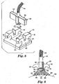
- a quantity of light curable bonding adhesive 56 (such as TRANSBOND brand adhesive from 3M Unitek) is placed on the bracket base 22 in contact with the pegs 26 as well as over the opening 24.
- the bracket 20 with the adhesive 56 is placed onto the exterior surface of a patient's tooth 58.
- the quantity of adhesive 56 initially placed on the base 20 is greater than the quantity of adhesive 56 that is needed to ultimately bond the bracket 20 to the tooth 58.
- portions 60 of the adhesive 56 are extruded from the four peripheral sides of the bracket base 22. The shifting movement and extrusion of the adhesive 56 reduces the likelihood of gaps or voids in the adhesive 56 in regions between the bracket base 22 and the surface of the tooth 58.
- the housing 44 of the curing light assembly 40 is moved toward the bracket 20 in the direction shown by the arrow in Fig. 7 and in such a manner that the central, longitudinal axis of the housing 44 including the outer end portion 46 is collinear with the central longitudinal axis of the passage 36.
- the housing 44 is rotated as needed about its longitudinal axis in order to align the tabs 52 with the archwire slot 34.
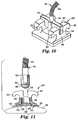
- the curing light assembly 40 continues to move toward the bracket 20 until the outer end portion 46 enters the passage 36 and the tabs 52 are received in the archwire slot 34 in the coupled-together manner shown in Figs. 9 and 10.
- the orthodontist shifts the bracket 20 relative to the tooth 58 slightly as needed to place the bracket 20 in the precise, desired position on the tooth 58.
- the orthodontist may shift the bracket 20 until the archwire slot 34 is aligned with the occlusal plane of the patient and the edges of the tiewings 30, 32 are aligned with the longitudinal axis of the tooth 58.
- the positioning of the bracket 20, including movements in occlusal-gingival directions, mesial-distal directions or rotational movements about the central axis of the passage 36 are carried out by moving the housing 44 relative to the tooth 58, inasmuch as the tabs 52 and the outer end portion 46 serve to control movement of the bracket 20.
- the tabs 52 also serve as a coupler for connecting the outer end portion 46 to the bracket 20.
- the configuration of the housing 44 may need to be changed in order to facilitate placement of certain brackets.
- the orthodontist may prefer to bend the housing 44 to a curved configuration such as that shown in Fig. 5 when the curing light assembly 40 is used to bond brackets to molar teeth or bicuspid teeth.
- the orthodontist may prefer to change the configuration of the housing 44 to a straight configuration in instances where the bracket 20 is to be placed on relatively accessible teeth such as the patient's central or lateral teeth.
- the solid state emitter 48 is energized by depressing the switch 50.
- Light emitted from the emitter 48 reaches a portion of the adhesive (designated 62 in Fig. 11) that is located between the central section of the bracket body 28 and the tooth 58.
- the adhesive portion 62 cures and provides a "tack" bond that temporarily secures the bracket 20 to the tooth 58.
- the curing light assembly 40 is removed from the bracket 20 by moving the housing 44 away from the bracket body 28 in the direction of the arrow until the outer end portion 46 is removed from the passage 36 and the tabs 52 are removed from the archwire slot 34.
- the orthodontist then uses a dental explorer or other tool to remove the extruded adhesive portions 60 from the tooth 58 adjacent the four peripheral edges of the bracket base 22.
- the cured adhesive portion 62 couples the bracket 20 to the tooth 58 with sufficient force to normally retain the bracket 20 in place if, for example, the bracket 20 is accidentally bumped or disturbed during the cleaning procedure.
- the use of light in the passage 34 does not substantially cure the adhesive 56 other than the cured portion 62, and thus the extruded adhesive portions 60 are not hardened and can be readily removed from the surface of the tooth 58.
- the curing light assembly 40 can be used when uncoupled from the bracket 20 for such peripheral curing, or another curing light assembly, possibly emitting a greater intensity of light, can be used.
- the light is directed toward at least two of the four peripheral edges of the base 22 such as the mesial and distal side edge of the base 22.
- the curing light assembly 40 may be used to firmly press the bracket 20 onto the tooth 58 in addition to controlling the movement of the bracket 20.
- the bracket 20 may be coupled to the tabs 52 before the bracket 20 is placed on the surface of the tooth 58.
- the orthodontist may use adhesives that are less viscous than conventional orthodontic adhesives used for direct bonding. Less viscous adhesives flow around the undercuts and other microstructure of the bracket base 22 more readily than thicker, more viscous adhesives and thus may provide higher bond strengths than such thicker adhesives. Drift of the bracket 20 on the tooth 58 before the adhesive is cured can be avoided because the curing light assembly 40 controls movement of the bracket 20 until tack bonded. In the past, however, relatively thick adhesives have been generally preferred because such adhesives hinder drift of the bracket 20 after placement on the tooth 58.
- the solid state light emitter 48 is a blue light emitting diode that emits light having a wavelength substantially in the range of about 413 nanometers to about 535 nanometers, and preferably emits the greatest intensity at a wavelength of about 450 nanometers.
- Suitable blue light emitting diodes include no. NLPB 500 from Nichia Chemical Industries, Ltd. Other wavelengths are also possible.
- the outer hemispherical lens of the LED is preferably sculpted to fit within the passage 36 and to direct the majority of its light along the longitudinal axis of the passage 36.
- the light emitted by the emitter 48 in the passage 36 is of an intensity sufficient to cure the adhesive portion 62 in less than about 10 seconds, and more preferably in less than about 4 seconds.
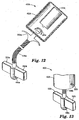
- FIG. 12 A second embodiment of a curing light assembly 40a according to another aspect of the invention is shown in Fig. 12.
- the assembly 40a includes a case 42a that in this instance includes a source of light such as a bulb 43a.
- a single solid state light emitter or a cluster of solid state light emitters may be employed in place of the bulb 43a.
- the case 42a also contains a source of power comprising a battery 41a that is electrically connected to the bulb 43a.
- a spring loaded finger switch 50a is movably connected to the case 42a. When the switch 50a is depressed, the battery 41a energizes the bulb 43a.
- the assembly 40a also includes an elongated housing 44a that, in this instance, comprises a bundle of optical fibers.
- the bundle of optical fibers is somewhat flexible, and yet sufficiently stiff to retain a desired configuration when repositioned.
- the housing 44a in this embodiment is provided by the outer cladding of the fibers arranged around the periphery of the bundle.
- the bundle of optical fibers may be received inside of a flexible housing (such as the gooseneck mentioned above).
- a single optical fiber may be used, and in such case the housing 44a may comprise the cladding of such fiber, or instead may comprise a separate, flexible tubular member surrounding such cladding.
- the housing 44a includes an enlarged outer end portion 46a that preferably is provided with a release coating or other release means as mentioned above.
- a pair of tabs 52a are connected to the housing 44a directly adjacent the outer end portion 46a.
- the tabs 52a are identical to the tabs 52 described above.
- a curing light assembly 40b according to another aspect of the invention is illustrated in Fig. 13.
- the assembly 40b includes a case 42b that, in this instance, is relatively small and is not illustrated to scale.
- the case 42b is just slightly larger in diameter than the diameter of a conventional "AAA" size battery that is contained within.
- the case 42b has a shape similar to a pencil for easy grasping and manipulation.
- the case 42b is connected to and optionally is detachably connected to a relatively short housing 44b that has an outer end portion 46b.
- a solid state light emitter (such as the blue light emitting diode mentioned above) is contained in the outer end portion 46b. Moreover, a pair of tabs 52b similar to the tabs 52 described above are connected to the housing 44b. A push-button switch 50b is mounted on the side of the case 42b to close the circuit and energize the solid state emitter when desired.
- a curing light assembly 40c according to yet another embodiment of the invention is illustrated in Fig. 14.
- the assembly 40c is somewhat similar to the light curing assembly 40 shown in Figs. 5 and 7-11, except that the assembly 40c includes a bracket height gauge 70c that is secured to a housing 44c.
- the gauge 70c includes a sleeve that is slidably received on the housing 44c and held in place by friction, such that the gauge 70c can be removed from the housing 44c and replaced with a similar or different gauge when desired.
- the gauge 70c has a generally L-shaped configuration with a first leg 72c and a second leg 74c that is integrally connected to the first leg 72 c.
- the length of the first leg 72c is selected so that the archwire slot of the bracket 20 is located a certain distance in an occlusal-gingival direction from the outermost end (i.e., the occlusal or incisal edge) of the tooth 58 when an underside edge portion of the second leg 74c is in contact with the occlusal edge of the tooth 58.
- the gauge 70c therefore positions the bracket 20 at a predetermined height on the tooth 58 until such time that light is emitted from an outer end portion 46c of the assembly 40c to thereafter retain the bracket 20 in place.
- the first leg 72c includes a series of indicia to provide additional structure for determining the distance of the archwire slot of the bracket 20 from the occlusal edge of the tooth 58.
- the indicia comprise a pair of edges or shoulders 76c that can be visually aligned, if desired, to the occlusal edge of the tooth in instances where it is desired to position the bracket 20 at a height on the tooth 58 other than the height provided when the second leg 74c is in contact with the occlusal edge.
- Other indicia, as well as an adjustable height gauge, are also possible.
- a base unit connected to line current may include a light source that is optically and detachably connected by a single optical fiber or a bundle of optical fibers to the outer end portion of the housing.
- the finger-operated switches 50, 50a or 50b may be replaced by a foot pedal switch or alternatively by a pressure sensitive switch that is operable to energize the emitter whenever sufficient pressure is applied to the bracket 20 by the curing light assembly 40, 40a, 40b, 40c.
- bracket 20 may be provided with a base having a mesh pad resembling fine wire mesh screening. If the mesh pad includes a layer of metallic foil bonded to the mesh screening, the foil is provided with one or more holes which would then serve as the opening of the base.
- Brackets made of materials other than metallic materials may also be employed.
- the bracket may be made of a transparent, translucent or opaque plastic or ceramic material. If the bracket is made of a material that transmits light, the intensity of light emitted by the curing light assembly is preferably relatively low. Such lower intensity is sufficient, to cure the adhesive directly beneath the central section of the bracket body, but insufficient to cure adhesive near the peripheral edges of the bracket base so that extruded adhesive can be removed from the tooth surface with ease.
- Brackets having archwire slot liners may also be used in connection with the present invention. Suitable brackets with liners are described, for example, in U.S. Patent Nos. 5,380,196 and 5,366,372.
- the liner would comprise part of the bracket body and would include a hole to provide a passage that is aligned with an opening in the bracket base so that light can pass to adhesive beneath a central portion of the bracket base.
- the invention may also be used with indirect bonding procedures.
- an indirect bonding procedure a set of the brackets is temporarily tack bonded in a laboratory to a model of the patient's teeth while each bracket is maintained in a certain position relative to each other and relative to the patient's model teeth. The set of brackets is then removed as a unit from the model and rebonded to the patient's actual teeth while their relative positions are maintained.
Landscapes
- Health & Medical Sciences (AREA)
- Oral & Maxillofacial Surgery (AREA)
- Dentistry (AREA)
- Epidemiology (AREA)
- Life Sciences & Earth Sciences (AREA)
- Animal Behavior & Ethology (AREA)
- General Health & Medical Sciences (AREA)
- Public Health (AREA)
- Veterinary Medicine (AREA)
- Dental Tools And Instruments Or Auxiliary Dental Instruments (AREA)
Applications Claiming Priority (3)
| Application Number | Priority Date | Filing Date | Title |
|---|---|---|---|
| US575095 | 1984-01-30 | ||
| US08/575,095 US5711665A (en) | 1995-12-19 | 1995-12-19 | Method and apparatus for bonding orthodontic brackets to teeth |
| EP96113844A EP0780101B1 (de) | 1995-12-19 | 1996-08-29 | Orthodontische Klammer und angepasste Einrichtung zum Aushärten mittels Licht |
Related Parent Applications (1)
| Application Number | Title | Priority Date | Filing Date |
|---|---|---|---|
| EP96113844A Division EP0780101B1 (de) | 1995-12-19 | 1996-08-29 | Orthodontische Klammer und angepasste Einrichtung zum Aushärten mittels Licht |
Publications (2)
| Publication Number | Publication Date |
|---|---|
| EP1484029A2 true EP1484029A2 (de) | 2004-12-08 |
| EP1484029A3 EP1484029A3 (de) | 2005-01-26 |
Family
ID=24298920
Family Applications (2)
| Application Number | Title | Priority Date | Filing Date |
|---|---|---|---|
| EP04019175A Withdrawn EP1484029A3 (de) | 1995-12-19 | 1996-08-29 | Orthodontisches Bracket und damit zusammenpassende Beleuchtungsanordnung zum Polymerisieren |
| EP96113844A Expired - Lifetime EP0780101B1 (de) | 1995-12-19 | 1996-08-29 | Orthodontische Klammer und angepasste Einrichtung zum Aushärten mittels Licht |
Family Applications After (1)
| Application Number | Title | Priority Date | Filing Date |
|---|---|---|---|
| EP96113844A Expired - Lifetime EP0780101B1 (de) | 1995-12-19 | 1996-08-29 | Orthodontische Klammer und angepasste Einrichtung zum Aushärten mittels Licht |
Country Status (4)
| Country | Link |
|---|---|
| US (1) | US5711665A (de) |
| EP (2) | EP1484029A3 (de) |
| JP (1) | JP3805846B2 (de) |
| DE (3) | DE29624613U1 (de) |
Cited By (1)
| Publication number | Priority date | Publication date | Assignee | Title |
|---|---|---|---|---|
| EP1300118B1 (de) * | 2001-10-02 | 2008-12-24 | Tp Orthodontics, Inc. | Verklebbare orthodontische Vorrichtung |
Families Citing this family (177)
| Publication number | Priority date | Publication date | Assignee | Title |
|---|---|---|---|---|
| DE29709228U1 (de) * | 1997-05-26 | 1998-09-24 | THERA Patent GmbH & Co. KG Gesellschaft für industrielle Schutzrechte, 82229 Seefeld | Lichtpolymerisationsgerät |
| GB2329756A (en) | 1997-09-25 | 1999-03-31 | Univ Bristol | Assemblies of light emitting diodes |
| US6200134B1 (en) | 1998-01-20 | 2001-03-13 | Kerr Corporation | Apparatus and method for curing materials with radiation |
| EP0950383A3 (de) * | 1998-04-14 | 2002-06-19 | DENTSPLY DETREY GmbH | Tragbare Photohärtungsvorrichtung |
| SE513533C2 (sv) * | 1998-07-01 | 2000-09-25 | Kent Saefstroem | Tandsmycke |
| US6514075B1 (en) | 1998-09-15 | 2003-02-04 | Gregory S. Jacob | Dental curing apparatus for light-sensitive materials |
| US6077073A (en) * | 1998-09-15 | 2000-06-20 | Jacob; Gregory S. | Light emitting diode-array light apparatus |
| US11026768B2 (en) | 1998-10-08 | 2021-06-08 | Align Technology, Inc. | Dental appliance reinforcement |
| US6755649B2 (en) | 1999-09-24 | 2004-06-29 | Cao Group, Inc. | Curing light |
| US6981867B2 (en) | 1999-09-24 | 2006-01-03 | Cao Group, Inc. | Curing light |
| US6971875B2 (en) | 1999-09-24 | 2005-12-06 | Cao Group, Inc. | Dental curing light |
| US7077648B2 (en) * | 1999-09-24 | 2006-07-18 | Cao Group, Inc. | Curing light |
| US6824294B2 (en) * | 1999-09-24 | 2004-11-30 | Cao Group, Inc. | Light for use in activating light-activated materials, the light having a plurality of chips mounted in a gross well of a heat sink, and a dome covering the chips |
| US7294364B2 (en) * | 1999-09-24 | 2007-11-13 | Cao Group, Inc. | Method for curing composite materials |
| US6932600B2 (en) * | 1999-09-24 | 2005-08-23 | Cao Group, Inc. | Curing light |
| US6988891B2 (en) * | 1999-09-24 | 2006-01-24 | Cao Group, Inc. | Curing light |
| US6926524B2 (en) * | 1999-09-24 | 2005-08-09 | Cao Group, Inc. | Curing light |
| US6953340B2 (en) * | 1999-09-24 | 2005-10-11 | Cao Group, Inc. | Light for use in activating light-activated materials, the light having a detachable light module containing a heat sink and a semiconductor chip |
| US6929472B2 (en) | 1999-09-24 | 2005-08-16 | Cao Group, Inc. | Curing light |
| US6910886B2 (en) | 1999-09-24 | 2005-06-28 | Cao Group, Inc. | Curing light |
| US6979193B2 (en) | 1999-09-24 | 2005-12-27 | Cao Group, Inc. | Curing light |
| US7066732B2 (en) * | 1999-09-24 | 2006-06-27 | Cao Group, Inc. | Method for curing light-curable materials |
| US6988890B2 (en) | 1999-09-24 | 2006-01-24 | Cao Group, Inc. | Curing light |
| US6974319B2 (en) * | 1999-09-24 | 2005-12-13 | Cao Group, Inc. | Curing light |
| US6719559B2 (en) | 1999-09-24 | 2004-04-13 | Densen Cao | Curing light |
| US6755648B2 (en) | 1999-09-24 | 2004-06-29 | Cao Group, Inc. | Curing light |
| US6780010B2 (en) | 1999-09-24 | 2004-08-24 | Cao Group, Inc. | Curing light |
| US6719558B2 (en) | 1999-09-24 | 2004-04-13 | Densen Cao | Curing light |
| US6971876B2 (en) | 1999-09-24 | 2005-12-06 | Cao Group, Inc. | Curing light |
| US6318996B1 (en) * | 1999-10-05 | 2001-11-20 | Noureddine Melikechi | Method for curing a dental composition using a light emitting diode |
| US6342204B1 (en) | 1999-10-27 | 2002-01-29 | Dakota Dental Development, Inc | Flavored tooth conditioning compositions and methods for using the compositions to condition a tooth surface |
| US6342203B2 (en) | 1999-10-27 | 2002-01-29 | Dakota Dental Development, Inc. | Compositions for dentistry comprising an oil, to repair, restore, adhere to, or protect the surface of a tooth |
| US6371760B1 (en) | 1999-12-22 | 2002-04-16 | Tony Zavilenski | Method and apparatus for welding orthodontic article and an orthodontic article |
| US20040229186A1 (en) * | 2000-02-11 | 2004-11-18 | Slone Charles E. | Dental hand tool for interproximal dental restorations |
| US6419483B1 (en) | 2000-03-01 | 2002-07-16 | 3M Innovative Properties Company | Method and apparatus for curling light-curable dental materials |
| US7320593B2 (en) | 2000-03-08 | 2008-01-22 | Tir Systems Ltd. | Light emitting diode light source for curing dental composites |
| KR100379987B1 (ko) | 2000-08-25 | 2003-04-16 | 조재형 | 치열교정용 치아 브라켓의 정위 및 접착 보조장치 |
| US6528555B1 (en) * | 2000-10-12 | 2003-03-04 | 3M Innovative Properties Company | Adhesive for use in the oral environment having color-changing capabilities |
| WO2002033312A2 (en) * | 2000-10-19 | 2002-04-25 | Reipur Technology A/S | A light-emitting assembly |
| US6620859B2 (en) * | 2000-12-15 | 2003-09-16 | Dakota Dental Development, Inc. | Methods of preparing polymerizable dental compositions with improved taste or aroma, and that prevent oxygen-inhibited layer |
| US6482002B2 (en) | 2001-03-05 | 2002-11-19 | 3M Innovative Properties Company | Orthodontic appliance providing enhanced adhesive cure |
| US6511317B2 (en) | 2001-04-26 | 2003-01-28 | New Photonic, Llc | Device for curing photosensitive dental compositions with off-axis lens and method of curing |
| US6755647B2 (en) | 2001-04-26 | 2004-06-29 | New Photonics, Llc | Photocuring device with axial array of light emitting diodes and method of curing |
| US6468077B1 (en) | 2001-04-26 | 2002-10-22 | New Photonics, Llc | Compact device for curing dental compositions and method of curing |
| US6843370B2 (en) * | 2001-06-20 | 2005-01-18 | American Orthodontics | Package for prepasted orthodontic bracket |
| US6491408B1 (en) * | 2001-07-05 | 2002-12-10 | Spectronics Corporation | Pen-size LED inspection lamp for detection of fluorescent material |
| US7108504B2 (en) | 2001-07-10 | 2006-09-19 | Cao Group, Inc. | Light for use in activating light-activated materials, the light having insulators and an air jacket |
| US6799967B2 (en) | 2001-07-10 | 2004-10-05 | Cao Group, Inc. | Light for use in activating light-activated materials, the light having a plurality of light emitting single chip arrays |
| US6647761B2 (en) * | 2001-07-12 | 2003-11-18 | Mastercool, Inc. | Hand held flexible mount leak detector |
| US6940659B2 (en) * | 2002-01-11 | 2005-09-06 | Ultradent Products, Inc. | Cone-shaped lens having increased forward light intensity and kits incorporating such lenses |
| US20030148242A1 (en) * | 2002-02-05 | 2003-08-07 | Fischer Dan E. | Lightweight hand held dental curing device |
| US7106523B2 (en) | 2002-01-11 | 2006-09-12 | Ultradent Products, Inc. | Optical lens used to focus led light |
| US20030215766A1 (en) * | 2002-01-11 | 2003-11-20 | Ultradent Products, Inc. | Light emitting systems and kits that include a light emitting device and one or more removable lenses |
| WO2003075782A1 (de) * | 2002-03-13 | 2003-09-18 | Christoph Von Mandach | Verfahren zum anbringen von kieferorthopädischen befestigungsteilen |
| US20030186195A1 (en) * | 2002-04-02 | 2003-10-02 | Comfort Biomedical, Inc. | Hand-held medical/dental tool |
| US20030186193A1 (en) * | 2002-04-02 | 2003-10-02 | Comfort Biomedical, Inc. | Hand-held medical/dental tool |
| EP1503690A1 (de) * | 2002-05-02 | 2005-02-09 | Cadent Ltd. | Vorrichtung zur positionierung von orthodontischen komponenten |
| US20030230377A1 (en) * | 2002-06-14 | 2003-12-18 | Turvey Robert R. | Apparatus and method for automated splicing of closer tape |
| KR101164758B1 (ko) | 2002-07-25 | 2012-07-12 | 조나단 에스. 담 | 경화용 발광 다이오드를 사용하기 위한 방법 및 장치 |
| US7182597B2 (en) | 2002-08-08 | 2007-02-27 | Kerr Corporation | Curing light instrument |
| AU2003298561A1 (en) * | 2002-08-23 | 2004-05-13 | Jonathan S. Dahm | Method and apparatus for using light emitting diodes |
| DE10250006A1 (de) * | 2002-10-25 | 2004-05-19 | Sirona Dental Systems Gmbh | Verfahren zur lagerichtigen Herstellung einer Kavität, insbesondere einer Knochenkavität und Instrument hierfür |
| US20040101802A1 (en) * | 2002-11-21 | 2004-05-27 | Scott Robert R. | Wide bandwidth led curing light |
| US6890175B2 (en) * | 2002-12-18 | 2005-05-10 | Ultradent Products, Inc. | Cooling system for hand-held curing light |
| US6994546B2 (en) * | 2002-12-18 | 2006-02-07 | Ultradent Products, Inc. | Light curing device with detachable power supply |
| US7125249B1 (en) * | 2003-01-22 | 2006-10-24 | Great Lakes Orthodontics, Ltd. | Electrically powered orthodontic bracket and bonding method |
| USD530013S1 (en) | 2003-02-18 | 2006-10-10 | Ultradent Products, Inc. | Dental illumination device |
| US20040214131A1 (en) * | 2003-04-25 | 2004-10-28 | Ultradent Products, Inc., | Spot curing lens used to spot cure a dental appliance adhesive and systems and methods employing such lenses |
| US7192276B2 (en) * | 2003-08-20 | 2007-03-20 | Ultradent Products, Inc. | Dental curing light adapted to emit light at a desired angle |
| US7137812B2 (en) | 2003-10-03 | 2006-11-21 | 3M Innovative Properties Company | Apparatus for indirect bonding of orthodontic appliances and method of making the same |
| US20050074717A1 (en) * | 2003-10-03 | 2005-04-07 | 3M Innovative Properties Company | Method and apparatus for bonding orthodontic appliances to teeth |
| JP4051048B2 (ja) * | 2003-12-05 | 2008-02-20 | 有限会社デント商事 | 歯列矯正用ブラケット |
| US7144250B2 (en) | 2003-12-17 | 2006-12-05 | Ultradent Products, Inc. | Rechargeable dental curing light |
| US7195482B2 (en) * | 2003-12-30 | 2007-03-27 | Ultradent Products, Inc. | Dental curing device having a heat sink for dissipating heat |
| US9492245B2 (en) | 2004-02-27 | 2016-11-15 | Align Technology, Inc. | Method and system for providing dynamic orthodontic assessment and treatment profiles |
| US7074040B2 (en) * | 2004-03-30 | 2006-07-11 | Ultradent Products, Inc. | Ball lens for use with a dental curing light |
| US7094052B2 (en) * | 2004-04-30 | 2006-08-22 | Norbert Abels | Orthodontic brackets with temporarily visible marking features |
| US7153130B2 (en) * | 2004-06-10 | 2006-12-26 | 3M Innovative Properties Company | Orthodontic appliance with removable insert |
| CN100594327C (zh) * | 2004-06-15 | 2010-03-17 | 汉高公司 | 大功率led电-光学器件组件 |
| US7913002B2 (en) * | 2004-08-20 | 2011-03-22 | Advantest Corporation | Test apparatus, configuration method, and device interface |
| US7134872B2 (en) * | 2004-09-02 | 2006-11-14 | Norbert Abels | Colored orthodontic brackets |
| US7056116B2 (en) * | 2004-10-26 | 2006-06-06 | Ultradent Products, Inc. | Heat sink for dental curing light comprising a plurality of different materials |
| WO2006049703A1 (en) * | 2004-10-28 | 2006-05-11 | Henkel Corporation | Led assembly with led-reflector interconnect |
| JP2006167212A (ja) * | 2004-12-16 | 2006-06-29 | Tomii Kk | 歯列矯正部材 |
| US7321004B2 (en) * | 2005-02-11 | 2008-01-22 | New Photonics, Llc | Method for photo-curing polymerizable compositions |
| US7407616B2 (en) * | 2005-02-11 | 2008-08-05 | New Photonics, Llc | Method for photo-curing polymerizable compositions with pulsed light |
| USD543280S1 (en) | 2005-04-01 | 2007-05-22 | Ajit Khubani | Light activated tooth whitening apparatus |
| US20060252005A1 (en) * | 2005-05-06 | 2006-11-09 | Feinbloom Richard E | Apparatus for providing radiation at multiple wavelengths and method of operating same |
| US8113830B2 (en) * | 2005-05-27 | 2012-02-14 | Kerr Corporation | Curing light instrument |
| US9682036B2 (en) * | 2005-06-01 | 2017-06-20 | Cao Group, Inc. | Hot melt dental materials and devices and methods for using the same |
| US20070037113A1 (en) * | 2005-08-10 | 2007-02-15 | Scott Robert R | Dental curing light including a light integrator for providing substantially equal distribution of each emitted wavelength |
| US20070054230A1 (en) * | 2005-09-02 | 2007-03-08 | Naphtali Brezniak | Dental brackets or attachments and methods and devices for using the same |
| MXPA05014182A (es) * | 2005-12-21 | 2007-06-20 | Rodriguez Francisco Javier Marichi | Aparato de medicion de programacion y soldado de brackets ajustables. |
| MXPA05014181A (es) | 2005-12-21 | 2007-06-20 | Roberto Ruiz Diaz | Sistema de brackets totalmente ajustables. |
| US7611352B2 (en) * | 2006-08-31 | 2009-11-03 | Ultradent Products, Inc. | Lifestyle bracket system having interchangeable ligation covers |
| US8047686B2 (en) | 2006-09-01 | 2011-11-01 | Dahm Jonathan S | Multiple light-emitting element heat pipe assembly |
| WO2008030240A1 (en) * | 2006-09-07 | 2008-03-13 | American Orthodontics Corporation | Dental brackets or attachments and methods and devices for using the same |
| US8439671B2 (en) * | 2007-03-22 | 2013-05-14 | 3M Innovative Properties Company | Methods and apparatus for bonding orthodontic appliances using photocurable adhesive material |
| FR2915921B1 (fr) * | 2007-05-09 | 2018-03-16 | J3M Diffusion | Dispositif lumineux a led mains-libres pour photopolymerisation des resines composites |
| US7878805B2 (en) | 2007-05-25 | 2011-02-01 | Align Technology, Inc. | Tabbed dental appliance |
| US8738394B2 (en) | 2007-11-08 | 2014-05-27 | Eric E. Kuo | Clinical data file |
| US8108189B2 (en) | 2008-03-25 | 2012-01-31 | Align Technologies, Inc. | Reconstruction of non-visible part of tooth |
| US8092215B2 (en) | 2008-05-23 | 2012-01-10 | Align Technology, Inc. | Smile designer |
| US9492243B2 (en) | 2008-05-23 | 2016-11-15 | Align Technology, Inc. | Dental implant positioning |
| US8172569B2 (en) | 2008-06-12 | 2012-05-08 | Align Technology, Inc. | Dental appliance |
| JP5911303B2 (ja) * | 2008-06-26 | 2016-04-27 | スリーエム イノベイティブ プロパティズ カンパニー | 歯列矯正装具用のラピッドプロトタイプ移動トレー |
| US8152518B2 (en) | 2008-10-08 | 2012-04-10 | Align Technology, Inc. | Dental positioning appliance having metallic portion |
| WO2010093877A1 (en) * | 2009-02-12 | 2010-08-19 | Lawrence Kenneth H | Illuminated dental retractor |
| US8292617B2 (en) | 2009-03-19 | 2012-10-23 | Align Technology, Inc. | Dental wire attachment |
| US9066777B2 (en) | 2009-04-02 | 2015-06-30 | Kerr Corporation | Curing light device |
| US9072572B2 (en) | 2009-04-02 | 2015-07-07 | Kerr Corporation | Dental light device |
| WO2011005276A1 (en) * | 2009-07-10 | 2011-01-13 | Teasdale Russell C | Systems and methods for orthodontic devices |
| US8765031B2 (en) | 2009-08-13 | 2014-07-01 | Align Technology, Inc. | Method of forming a dental appliance |
| USD638944S1 (en) | 2009-09-22 | 2011-05-31 | Ultradent Products, Inc. | Dental illumination device |
| EP2538866A1 (de) * | 2010-02-25 | 2013-01-02 | Jean Beaudoin | Klammer mit vorderer öffnung und orthodontisches klammersystem mit klammerverbindungsmechanismus |
| US9241774B2 (en) | 2010-04-30 | 2016-01-26 | Align Technology, Inc. | Patterned dental positioning appliance |
| US9211166B2 (en) | 2010-04-30 | 2015-12-15 | Align Technology, Inc. | Individualized orthodontic treatment index |
| US9055987B2 (en) * | 2010-12-20 | 2015-06-16 | DePuy Synthes Products, Inc. | Kit for implanting heat deformable fixation elements of different sizes |
| US10433933B2 (en) | 2011-03-17 | 2019-10-08 | Cameron Mashouf | Orthodontic bracket for use on deciduous teeth |
| US11382722B2 (en) * | 2011-03-17 | 2022-07-12 | Cameron Mashouf | Orthodontic brackets for deciduous teeth |
| US9403238B2 (en) | 2011-09-21 | 2016-08-02 | Align Technology, Inc. | Laser cutting |
| BR112014010995B1 (pt) * | 2011-11-08 | 2020-10-13 | Orthodontic Research And Development, S.L. | aparelho ortodôntico, base para aparelho ortodôntico e bráquete |
| US9375300B2 (en) | 2012-02-02 | 2016-06-28 | Align Technology, Inc. | Identifying forces on a tooth |
| US9220580B2 (en) | 2012-03-01 | 2015-12-29 | Align Technology, Inc. | Determining a dental treatment difficulty |
| US9414897B2 (en) | 2012-05-22 | 2016-08-16 | Align Technology, Inc. | Adjustment of tooth position in a virtual dental model |
| US10449016B2 (en) | 2014-09-19 | 2019-10-22 | Align Technology, Inc. | Arch adjustment appliance |
| US9610141B2 (en) | 2014-09-19 | 2017-04-04 | Align Technology, Inc. | Arch expanding appliance |
| US9895206B2 (en) * | 2014-10-03 | 2018-02-20 | Mohammad Izadi | Adjustable orthodontic bracket and method using a microstructured shape memory polymer surface with reversible dry adhesion |
| US20160095671A1 (en) * | 2014-10-03 | 2016-04-07 | Mohammad Izadi | Adjustable orthodontic bracket and method |
| US20160095669A1 (en) * | 2014-10-03 | 2016-04-07 | Mohammad Izadi | Adjustable orthodontic bracket and method |
| US9744001B2 (en) | 2014-11-13 | 2017-08-29 | Align Technology, Inc. | Dental appliance with cavity for an unerupted or erupting tooth |
| US10504386B2 (en) | 2015-01-27 | 2019-12-10 | Align Technology, Inc. | Training method and system for oral-cavity-imaging-and-modeling equipment |
| US11931222B2 (en) * | 2015-11-12 | 2024-03-19 | Align Technology, Inc. | Dental attachment formation structures |
| US11554000B2 (en) * | 2015-11-12 | 2023-01-17 | Align Technology, Inc. | Dental attachment formation structure |
| US11103330B2 (en) | 2015-12-09 | 2021-08-31 | Align Technology, Inc. | Dental attachment placement structure |
| US11596502B2 (en) | 2015-12-09 | 2023-03-07 | Align Technology, Inc. | Dental attachment placement structure |
| GB201608059D0 (en) * | 2016-05-09 | 2016-06-22 | Dickenson Gary | Method and apparatus for positioning a dental bracket element |
| ITUA20164090A1 (it) * | 2016-06-03 | 2017-12-03 | Giovanbattista Pagnotta | Dispositivo ortodontico |
| WO2017218947A1 (en) | 2016-06-17 | 2017-12-21 | Align Technology, Inc. | Intraoral appliances with sensing |
| EP3988048B1 (de) | 2016-06-17 | 2024-01-17 | Align Technology, Inc. | Leistungsüberwachung einer kieferorthopädischen vorrichtung |
| EP4603050A3 (de) | 2016-07-27 | 2025-11-05 | Align Technology, Inc. | Verfahren und vorrichtungen für intraorales scannen |
| WO2018085718A2 (en) | 2016-11-04 | 2018-05-11 | Align Technology, Inc. | Methods and apparatuses for dental images |
| WO2018102702A1 (en) | 2016-12-02 | 2018-06-07 | Align Technology, Inc. | Dental appliance features for speech enhancement |
| CN119925011A (zh) | 2016-12-02 | 2025-05-06 | 阿莱恩技术有限公司 | 腭扩张器和扩张腭的方法 |
| WO2018102770A1 (en) | 2016-12-02 | 2018-06-07 | Align Technology, Inc. | Force control, stop mechanism, regulating structure of removable arch adjustment appliance |
| CA3043049A1 (en) | 2016-12-02 | 2018-06-07 | Align Technology, Inc. | Methods and apparatuses for customizing rapid palatal expanders using digital models |
| JP7153648B2 (ja) * | 2016-12-16 | 2022-10-14 | スリーエム イノベイティブ プロパティズ カンパニー | 歯列矯正ブラケットフーチング |
| US10548700B2 (en) | 2016-12-16 | 2020-02-04 | Align Technology, Inc. | Dental appliance etch template |
| US10779718B2 (en) | 2017-02-13 | 2020-09-22 | Align Technology, Inc. | Cheek retractor and mobile device holder |
| WO2018183358A1 (en) | 2017-03-27 | 2018-10-04 | Align Technology, Inc. | Apparatuses and methods assisting in dental therapies |
| US10613515B2 (en) | 2017-03-31 | 2020-04-07 | Align Technology, Inc. | Orthodontic appliances including at least partially un-erupted teeth and method of forming them |
| US11045283B2 (en) | 2017-06-09 | 2021-06-29 | Align Technology, Inc. | Palatal expander with skeletal anchorage devices |
| CN116942335A (zh) | 2017-06-16 | 2023-10-27 | 阿莱恩技术有限公司 | 牙齿类型和萌出状态的自动检测 |
| WO2019005808A1 (en) | 2017-06-26 | 2019-01-03 | Align Technology, Inc. | BIOCAPTOR PERFORMANCE INDICATOR FOR INTRABUCCAL DEVICES |
| US10885521B2 (en) | 2017-07-17 | 2021-01-05 | Align Technology, Inc. | Method and apparatuses for interactive ordering of dental aligners |
| US11419702B2 (en) | 2017-07-21 | 2022-08-23 | Align Technology, Inc. | Palatal contour anchorage |
| WO2019023631A1 (en) | 2017-07-27 | 2019-01-31 | Align Technology, Inc. | SYSTEM AND METHODS FOR TREATING AN ORTHODONTIC ALIGNMENT USING OPTICAL COHERENCE TOMOGRAPHY |
| US11633268B2 (en) | 2017-07-27 | 2023-04-25 | Align Technology, Inc. | Tooth shading, transparency and glazing |
| US12274597B2 (en) | 2017-08-11 | 2025-04-15 | Align Technology, Inc. | Dental attachment template tray systems |
| WO2019035979A1 (en) | 2017-08-15 | 2019-02-21 | Align Technology, Inc. | EVALUATION AND CALCULATION OF BUCCAL CORRIDOR |
| US11123156B2 (en) | 2017-08-17 | 2021-09-21 | Align Technology, Inc. | Dental appliance compliance monitoring |
| WO2019071019A1 (en) | 2017-10-04 | 2019-04-11 | Align Technology, Inc. | INTRAORAL APPARATUS FOR SAMPLING MOUTH TISSUE |
| US10813720B2 (en) | 2017-10-05 | 2020-10-27 | Align Technology, Inc. | Interproximal reduction templates |
| US11534268B2 (en) | 2017-10-27 | 2022-12-27 | Align Technology, Inc. | Alternative bite adjustment structures |
| CN111295153B (zh) | 2017-10-31 | 2023-06-16 | 阿莱恩技术有限公司 | 具有选择性牙合负荷和受控牙尖交错的牙科器具 |
| CN119235481A (zh) | 2017-11-01 | 2025-01-03 | 阿莱恩技术有限公司 | 自动治疗规划 |
| WO2019100022A1 (en) | 2017-11-17 | 2019-05-23 | Align Technology, Inc. | Orthodontic retainers |
| WO2019108978A1 (en) | 2017-11-30 | 2019-06-06 | Align Technology, Inc. | Sensors for monitoring oral appliances |
| US11432908B2 (en) | 2017-12-15 | 2022-09-06 | Align Technology, Inc. | Closed loop adaptive orthodontic treatment methods and apparatuses |
| US10980613B2 (en) | 2017-12-29 | 2021-04-20 | Align Technology, Inc. | Augmented reality enhancements for dental practitioners |
| EP4056145B1 (de) | 2018-01-26 | 2024-07-10 | Align Technology, Inc. | Diagnostische intraorale abtastung und verfolgung |
| US11937991B2 (en) | 2018-03-27 | 2024-03-26 | Align Technology, Inc. | Dental attachment placement structure |
| CN111970990B (zh) | 2018-04-11 | 2023-04-18 | 阿莱恩技术有限公司 | 可释放的腭扩张器 |
| KR20210109542A (ko) * | 2018-12-31 | 2021-09-06 | 쓰리엠 이노베이티브 프로퍼티즈 컴파니 | 치과교정용 간접 접합 장치 |
| US10945816B1 (en) * | 2020-07-08 | 2021-03-16 | King Saud University | Orthodontic bracket positioning instrument |
| US20220061963A1 (en) * | 2020-09-01 | 2022-03-03 | Dean UltraThin Retainer, LLC | Patient specific dental appliances |
| EP4046588B1 (de) * | 2021-02-23 | 2024-06-19 | LYS Office | Kieferorthopädische höhenpositionierungslehre |
Citations (3)
| Publication number | Priority date | Publication date | Assignee | Title |
|---|---|---|---|---|
| US4094068A (en) | 1975-08-01 | 1978-06-13 | Scheu-Dental Inh. Rudolf Scheu Herstellung & Vertrieb Von Dentalbedarf | Orthodontic bracket assembly |
| USD290040S (en) | 1984-05-10 | 1987-05-26 | Unitek Corporation | Orthodontic bracket |
| US5435720A (en) | 1994-01-18 | 1995-07-25 | Riebschleger; Ronald P. | Retentive orthodontic dental bracket |
Family Cites Families (27)
| Publication number | Priority date | Publication date | Assignee | Title |
|---|---|---|---|---|
| US3932940A (en) * | 1971-12-06 | 1976-01-20 | Andren Frank J | Dental appliance |
| US4063360A (en) * | 1974-04-25 | 1977-12-20 | Dentsply Research & Development Corporation | Orthodontic bracket assembly and method for attachment |
| US3949477A (en) * | 1974-11-18 | 1976-04-13 | Morton Cohen | Orthodontic method and apparatus |
| US4256455A (en) * | 1978-04-27 | 1981-03-17 | Bernhard Forster Gmbh | Orthodontic bracket and orthodontic appliance |
| US4216583A (en) * | 1978-08-03 | 1980-08-12 | Zulauf Inc. | Orthodontic appliance |
| US4219617A (en) * | 1978-08-09 | 1980-08-26 | Melvin Wallshein | Ceramic orthodontic bracket |
| US4229658A (en) * | 1978-08-18 | 1980-10-21 | Dentsply Research & Development Corp. | Xenon light apparatus for supplying ultraviolet and visible spectra |
| US4478576A (en) * | 1982-06-01 | 1984-10-23 | Romada Holdings Ltd. | Orthodontic attachment placement device |
| US4666406A (en) * | 1984-01-13 | 1987-05-19 | Kanca Iii John | Photocuring device and method |
| US4952142B1 (en) * | 1984-07-20 | 1993-10-12 | Nicholson James | Method of bonding orthodontic brackets |
| DE3719561C2 (de) * | 1986-06-12 | 1998-12-10 | Morita Mfg | Medizinisches Lichtbestrahlungshandstück |
| US4850864A (en) * | 1987-03-30 | 1989-07-25 | Diamond Michael K | Bracket placing instrument |
| IL84367A (en) * | 1987-11-04 | 1994-02-27 | Amcor Ltd | Apparatus for use in radiation therapy |
| US5003434A (en) * | 1988-09-30 | 1991-03-26 | Den-Tal-Ez, Inc. | Miniature hand-held spot source of illumination |
| US5015180A (en) * | 1989-03-01 | 1991-05-14 | Minnesota Mining And Manufacturing Company | Dental article containing light-curable paste |
| US5049068A (en) * | 1990-01-31 | 1991-09-17 | Ormco Corporation | Method of using pulse radiation for bonding orthodentic brackets to teeth |
| US5098288A (en) * | 1990-05-04 | 1992-03-24 | Tp Orthodontics, Inc. | Flexible bonding pad for an orthodontic bracket |
| US5110290A (en) * | 1990-11-19 | 1992-05-05 | Ormco Corporation | Orthodontic bracket/mesh screen |
| CH685148A5 (de) * | 1991-11-20 | 1995-04-13 | Erik Larsen | Vorrichtung zur fotodynamischen Stimulierung von Zellen. |
| US5263859A (en) * | 1992-05-08 | 1993-11-23 | Tp Orthodontics, Inc. | Relatively flexible bonding pad for an orthodontic ceramic bracket |
| US5304061A (en) * | 1992-06-01 | 1994-04-19 | Nelson Edward J | Bracket height positioning dimple |
| EP0920840A3 (de) * | 1992-07-31 | 2000-03-29 | Molten Corporation | Kleines Lichtbestrahlungsgerät zum zahnärztlichen Gebrauch |
| CA2106020C (en) * | 1993-09-13 | 2002-11-19 | John Kennedy | A portable led photocuring device |
| US5420768A (en) * | 1993-09-13 | 1995-05-30 | Kennedy; John | Portable led photocuring device |
| US5366372A (en) * | 1993-11-29 | 1994-11-22 | Minnesota Mining And Manufacturing Company | Method and apparatus for debonding ceramic orthodontic brackets |
| CA2139078C (en) * | 1993-12-23 | 1998-04-21 | James A. Nicholson | Orthodontic brackets |
| JP2979522B2 (ja) * | 1994-02-28 | 1999-11-15 | 株式会社島津製作所 | 光重合型レジン硬化用光源装置 |
-
1995
- 1995-12-19 US US08/575,095 patent/US5711665A/en not_active Expired - Lifetime
-
1996
- 1996-08-29 DE DE29624613U patent/DE29624613U1/de not_active Expired - Lifetime
- 1996-08-29 DE DE0780101T patent/DE780101T1/de active Pending
- 1996-08-29 DE DE69633706T patent/DE69633706T2/de not_active Expired - Fee Related
- 1996-08-29 EP EP04019175A patent/EP1484029A3/de not_active Withdrawn
- 1996-08-29 EP EP96113844A patent/EP0780101B1/de not_active Expired - Lifetime
- 1996-12-13 JP JP33422696A patent/JP3805846B2/ja not_active Expired - Fee Related
Patent Citations (3)
| Publication number | Priority date | Publication date | Assignee | Title |
|---|---|---|---|---|
| US4094068A (en) | 1975-08-01 | 1978-06-13 | Scheu-Dental Inh. Rudolf Scheu Herstellung & Vertrieb Von Dentalbedarf | Orthodontic bracket assembly |
| USD290040S (en) | 1984-05-10 | 1987-05-26 | Unitek Corporation | Orthodontic bracket |
| US5435720A (en) | 1994-01-18 | 1995-07-25 | Riebschleger; Ronald P. | Retentive orthodontic dental bracket |
Cited By (1)
| Publication number | Priority date | Publication date | Assignee | Title |
|---|---|---|---|---|
| EP1300118B1 (de) * | 2001-10-02 | 2008-12-24 | Tp Orthodontics, Inc. | Verklebbare orthodontische Vorrichtung |
Also Published As
| Publication number | Publication date |
|---|---|
| EP0780101A2 (de) | 1997-06-25 |
| EP0780101A3 (de) | 1998-01-14 |
| EP1484029A3 (de) | 2005-01-26 |
| DE69633706T2 (de) | 2006-02-09 |
| JP3805846B2 (ja) | 2006-08-09 |
| JPH09173356A (ja) | 1997-07-08 |
| DE780101T1 (de) | 2003-09-18 |
| DE69633706D1 (de) | 2004-12-02 |
| DE29624613U1 (de) | 2005-03-03 |
| EP0780101B1 (de) | 2004-10-27 |
| US5711665A (en) | 1998-01-27 |
Similar Documents
| Publication | Publication Date | Title |
|---|---|---|
| EP0780101B1 (de) | Orthodontische Klammer und angepasste Einrichtung zum Aushärten mittels Licht | |
| EP1677700B1 (de) | Verfahren und gerät zur verbindung von orthodontischen geräten mit den zähnen | |
| US6482002B2 (en) | Orthodontic appliance providing enhanced adhesive cure | |
| US5487662A (en) | Dental impression tray for photocurable impression material | |
| US6893257B2 (en) | Orthodontic appliance with placement enhancement structure | |
| US7762815B2 (en) | Method of making an indirect bonding tray for orthodontic treatment | |
| EP1620031B1 (de) | Orthodontische vorrichtung mit konturierter verbindungsstruktur | |
| US8114327B2 (en) | Orthodontic indirect bonding tray with moisture control | |
| US7153130B2 (en) | Orthodontic appliance with removable insert | |
| EP2124811B1 (de) | Geräte zur verbindung von kieferorthopädischen apparaturen mit einem lichthärtbaren klebstoff | |
| US7841464B2 (en) | Packaged orthodontic appliance with user-applied adhesive | |
| WO2022236027A1 (en) | Systems, methods and devices for placement of orthodontic appliances and maintaining treatment results | |
| JP2001520913A (ja) | 歯科用の複合材の光硬化システム | |
| JPH08182689A (ja) | 耐荷重性フレームワークを有する美的プラスチック製歯科矯正用ブラケット | |
| JP2008516670A (ja) | 患者の歯に組成物を適用するための歯科矯正方法および装置 | |
| US20090068610A1 (en) | Dental brackets or attachments and methods and devices for using the same | |
| US7125249B1 (en) | Electrically powered orthodontic bracket and bonding method | |
| US20030186193A1 (en) | Hand-held medical/dental tool | |
| WO2008030240A1 (en) | Dental brackets or attachments and methods and devices for using the same |
Legal Events
| Date | Code | Title | Description |
|---|---|---|---|
| PUAI | Public reference made under article 153(3) epc to a published international application that has entered the european phase |
Free format text: ORIGINAL CODE: 0009012 |
|
| AC | Divisional application: reference to earlier application |
Ref document number: 0780101 Country of ref document: EP Kind code of ref document: P |
|
| AK | Designated contracting states |
Kind code of ref document: A2 Designated state(s): DE FR GB IT |
|
| PUAL | Search report despatched |
Free format text: ORIGINAL CODE: 0009013 |
|
| AK | Designated contracting states |
Kind code of ref document: A3 Designated state(s): DE FR GB IT |
|
| RIC1 | Information provided on ipc code assigned before grant |
Ipc: 7A 61C 7/12 B Ipc: 7A 61C 7/16 A Ipc: 7A 61C 19/00 B |
|
| 17P | Request for examination filed |
Effective date: 20050706 |
|
| AKX | Designation fees paid |
Designated state(s): DE FR GB IT |
|
| STAA | Information on the status of an ep patent application or granted ep patent |
Free format text: STATUS: THE APPLICATION IS DEEMED TO BE WITHDRAWN |
|
| 18D | Application deemed to be withdrawn |
Effective date: 20060329 |