EP1483985B1 - Verdeckbarer Handgriff für Türen, Schubladen, Flügel und dergleichen - Google Patents
Verdeckbarer Handgriff für Türen, Schubladen, Flügel und dergleichen Download PDFInfo
- Publication number
- EP1483985B1 EP1483985B1 EP04076613A EP04076613A EP1483985B1 EP 1483985 B1 EP1483985 B1 EP 1483985B1 EP 04076613 A EP04076613 A EP 04076613A EP 04076613 A EP04076613 A EP 04076613A EP 1483985 B1 EP1483985 B1 EP 1483985B1
- Authority
- EP
- European Patent Office
- Prior art keywords
- container body
- seat
- sliding element
- longitudinal
- container
- Prior art date
- Legal status (The legal status is an assumption and is not a legal conclusion. Google has not performed a legal analysis and makes no representation as to the accuracy of the status listed.)
- Expired - Lifetime
Links
- 230000013011 mating Effects 0.000 claims 1
- 230000000717 retained effect Effects 0.000 claims 1
Images


Classifications
-
- E—FIXED CONSTRUCTIONS
- E05—LOCKS; KEYS; WINDOW OR DOOR FITTINGS; SAFES
- E05B—LOCKS; ACCESSORIES THEREFOR; HANDCUFFS
- E05B5/00—Handles completely let into the surface of the wing
- E05B5/003—Pop-out handles, e.g. sliding outwardly before rotation
-
- A—HUMAN NECESSITIES
- A47—FURNITURE; DOMESTIC ARTICLES OR APPLIANCES; COFFEE MILLS; SPICE MILLS; SUCTION CLEANERS IN GENERAL
- A47B—TABLES; DESKS; OFFICE FURNITURE; CABINETS; DRAWERS; GENERAL DETAILS OF FURNITURE
- A47B95/00—Fittings for furniture
- A47B95/02—Handles
Definitions
- the present invention relates to a concealable gripping device for doors, drawers, leaves and the like.
- knobs It is known in the product sector of handles for doors and the like that there exists the need to provide inset devices which can be associated with knobs, handles and the like able to produce opening/closing of a leaf, door, drawer or the like; in greater detail it is required that said knobs should be of the type with a gripping element which is concealed when in the rest condition and extractable in the axial direction, when it needs to be used.
- a concealable gripping device is for instance known from document US-A-6 113 160.
- the technical problem posed, therefore, is that of providing a concealable gripping device able to be inset in the thickness of walls, doors, drawers and the like and provided with a gripping element which may in turn be extracted from/retracted into the thickness of the wall upon operation by the user.
- said device should have small dimensions, be easy and inexpensive to produce and should be able to be incorporated into conventional furnishing elements.
- a concealable gripping device comprising a container body able to be inserted in the thickness of a wall, a sliding element which is coaxial with the container body, provided with a head-piece and able to be displaced from a first position with the head-piece outside said container into a second position with the head-piece inside said container body and vice versa, and coaxial resilient means exerting a thrusting action on said sliding element relative to the said body, wherein said container body has at least one longitudinal guide suitable for engagement with a body shaped in the manner of a butterfly, radially projecting from said sliding element and free to rotate about a radial axis of the said sliding element, one end of said guide being provided with means able to cause rotation of said butterfly and means able to interfere with its travel along said guide so as to cause stoppage thereof.
- the concealable gripping device is essentially formed by a substantially cylindrical container body 10 having a seat 11 coaxially extending inside it along the whole length of the said body.
- the seat has, coaxially arranged inside it, a pin 12 supporting a spring 13, the length of which is much greater than the height of the body 10 in the longitudinal direction.
- the side surface of the container 10 is cut so as to define two opposite flat surfaces 10a from which two lugs 14 project outwards, being symmetrically arranged with respect to a longitudinal opening 15 (Fig. 5).
- the body 10 has, at its bottom end (with reference to the orientation shown by way of a non-limiting example in the figures) a thread 16 which is interrupted by recesses 16a which are diametrically opposite and in an angular position coinciding with said longitudinal openings.
- the cylindrical body 10 On the side axially opposite to the thread 16, the cylindrical body 10 has an end shaped in the manner of annular edge 17 which projects radially outwards and has formed inside it a concentric seat 17a of suitable thickness.
- the said longitudinal seat 11 slidably houses inside it a sliding element 20 essentially consisting of a cylindrical body in which there is coaxially formed a seat 21 able to contain the said spring 13 and the said pin 12, as will emerge more clearly below.
- the sliding element 20 has at one of its end a head-piece 22, the diameter and thickness of which are slightly smaller than the corresponding dimensions of the said seat 17a of the body 10.
- the side surface 20a of the sliding element 20 has two circular-shaped transverse seats 22b which are arranged in a diametrically opposite position and inside which a further radial hole 22a communicating with the coaxial seat 21 is coaxially formed.
- Said seats 22b form the housing for respective shaped bodies 30 consisting of a circular base 31 which has, respectively projecting from its opposite sides, a pin 32 able to be inserted inside the said hole 22a and a butterfly-shaped extension 33 from the centre of which a further pin 34 projects.
- the continuity of the side surface of the container body 10 is restored by means of two shaped flanges 40 which have a flat inner surface, an outer surface 40a with a curvature corresponding to the side surface 10a of the body 10, a bottom end having a tooth 41 able to be inserted inside said recess 16a, and two eyelets 44 suitable for engagement with said lugs 14.
- the inner surface of the flanges 40 has a longitudinal guide seat 43 (Figs. 1 and 6) which, at the end corresponding to the said tooth 41, has an inclined surface 43a which produces a widening 43b of said seat 43; on the opposite side to the said inclined seat 43a the widening 43b has an undercut 43c.
- a longitudinal depression 45 is formed on the bottom of the guide 43 and extends substantially along the whole length of the guide 43.
- the device is completed by a cover 50 with a female thread 51 suitable for mating with the thread 16 of the body 10 so as to prevent separation of said flanges 40.
- the length, in the axial direction, of the guide 43 and the seat 11 of the body 10 are greater than the length of the sliding element 20.
- Figs. 11 to 15 it is also possible to design the device so that it is applicable to inset handles 100 with a gripping element 122 rotatable from a first - rest - position concealed inside the handle into a second - working - position rotated outwards.
- the container body of the device consists of the side 100a of a handle 100 which is to be inset for example in a door schematically indicated by 1 and is formed by a box 102 with a bearing edge 100b and closed at the front by a cover 122 forming the gripping element of the handle.
- the side/container 100a has an eyelet 111 extending in the longitudinal direction over a suitable distance; a sliding element 120 is arranged inside the eyelet 111 and is provided at its bottom end (with the orientation shown in the figures by way of a non-limiting example) with a transverse seat 22b,22a having a circular shape inside which the shaped body 30 with a butterfly extension 33 is housed.
- the opposite end of the sliding element 120 has a hole 121a seating a pin 121 on which a first end of a rod 104 is pivotably mounted, the other end thereof being in turn pivotably mounted on the gripping element 122 by means of an associated pin 104a.
- the side/container 100a of the handle is also provided with two transverse extensions 14 directed outwards and suitable for engagement with the corresponding seats 44 of a shaped flange 40 entirely similar to that already described above and retained against the side 100a by screw means 150 which keep the device stably assembled.
- the gripping element 122 is integral with one end of a spring 113 which is arranged in an associated seat 113a with an orientation substantially at right angles to the sliding element 120 and the other end of which is constrained to the container 102 so as to form the element actuating the gripping element 22 and therefore the entire device.
- the external arrangement of the spring 113 allows the depth-wise dimensions of the assembly to be further reduced, allowing the inset mounting of the handle also in the thinnest doors of furniture which is currently produced.
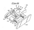
- Fig. 16 shows a further example of embodiment of the concealable gripping device according to the present invention for inset handles 200 having a gripping element movable with a translational movement.
- the body 210 is duplicated and has two parallel seats 211 for housing respective springs 13 partially inserted also in associated seats 221 of the gripping element 220 with a head-piece 222 which extends in the transverse direction, for covering the whole device.
- the transverse seat 22b containing the shaped element 30 with butterfly 33 is formed in the section joining together the two parallel seats 221.
- the body 210 has the already described extensions 214 for engagement with at least one shaped flange 40 entirely similar to that already described above.
- the body 210 can then be engaged with an end closing cover 250 able to interfere and retain the shaped flange 40 so as to keep the device stably assembled; the cover 250 also has outwardly extending pins 212 able to penetrate coaxially inside the seat 211 so as to form the guide of the spring 13.
- Said cover 250 also has force-fitting means 251 for engagement with associated seats 216 in the container body 220.
Landscapes
- Details Of Rigid Or Semi-Rigid Containers (AREA)
- Lock And Its Accessories (AREA)
- Steering Controls (AREA)
- Purses, Travelling Bags, Baskets, Or Suitcases (AREA)
- Slide Fasteners (AREA)
- Cartons (AREA)
Claims (40)
- Verbergbare Greifvorrichtung mit mindestens einem Aufnehmerkörper (10;110;210), einem dem Aufnehmerkörper (10;110,210) zugeordneten Gleitelement (20;120;220), das mit einem Greifelement (22;122;222) verbunden ist und sich von einer ersten Position, in der das Greifelement (22;122;222) von dem Aufnehmer (10; 110;210) absteht, in eine zweite Position, in der das Greifelement (22;122;222) mit dem Aufnehmerkörper (10;110;220) in Berührung steht, bewegen kann und umgekehrt, und mit elastischen Mitteln (13;113), die eine Schubkraft auf das Gleitelement im Verhältnis zu dem Aufnehmerkörper (10,110,210) ausüben, dadurch gekennzeichnet, dass der Aufnehmerkörper (10;110,210) mindestens einer Längsführung (43) zugeordnet ist, die zum Eingreifen mit einem in der Art eines Schmetterlings (33) geformten Körper (30) geeignet ist, der von dem Gleitelement (20;120;220) in eine Richtung quer dazu ragt und frei um die Querrichtung drehen kann, wobei ein Ende der Führung (43) mit einem Mittel (43a), das eine Drehung des Schmetterlings (33) bewirken kann, und mit einem Mittel (43c), das dessen Verfahrweg entlang der Führung (43) zum Bewirken des Anhaltens desselben in der ersten oder zweiten Position beeinträchtigen kann, versehen ist.
- Vorrichtung nach Anspruch 1, dadurch gekennzeichnet, dass der Aufnehmerkörper (10;110;210) innen mit einem sich entlang der Länge des Aufnehmerkörpers (10;110;210) erstreckenden Längssitz (11;111;211) versehen ist.
- Vorrichtung nach Anspruch 1, dadurch gekennzeichnet, dass die Seitenfläche des Aufnehmerkörpers (10;110;210) so geschnitten ist, dass sie mindestens eine flache Oberfläche (10a;110a;210a) bildet, auf welcher eine mit dem Längssitz (11) in Verbindung stehende jeweilige Längsöffnung (15) ausgebildet ist.
- Vorrichtung nach Anspruch 3, dadurch gekennzeichnet, dass mindestens eine Nase (14) von der mindestens einen Seitenfläche (10a;110a;210a) nach außen ragt.
- Vorrichtung nach Anspruch 4, dadurch gekennzeichnet, dass die Nasen (14) bezüglich der Längsöffnung (15) symmetrisch angeordnet sind.
- Vorrichtung nach Anspruch 1, dadurch gekennzeichnet, dass die Seitenfläche (20a;120a;220a) des Gleitelements (20;120;220) mindestens einen kreisförmigen Sitz (22b) aufweist, der darin koaxial ausgebildet eine mit dem koaxialen Sitz (21) in Verbindung stehende weitere radiale Öffnung (22a) aufweist.
- Vorrichtung nach Anspruch 6, dadurch gekennzeichnet, dass der mindestens eine Sitz (22b) am Ende des Gleitelements (20;120;220) gegenüber dem Greifelement (22;122;222) angeordnet ist.
- Vorrichtung nach Anspruch 1, dadurch gekennzeichnet, dass das Schmetterlingselement (33) einen festen Teil eines Körpers (30) bildet, der einen kreisförmigen Grundteil (31) umfasst, von dessen gegenüberliegenden Seiten ein in die Öffnung (22a) einführbarer Stift (32) und die Schmetterlingsverlängerung (33) jeweils abstehen.
- Vorrichtung nach Anspruch 1, dadurch gekennzeichnet, dass ein weiterer Stift (34) von der Mitte der Schmetterlingsverlängerung (33) absteht.
- Vorrichtung nach Anspruch 1, dadurch gekennzeichnet, dass mindestens ein abnehmbarer geformter Flansch (40), der eine flache Innenfläche aufweist, der Seitenfläche des Aufnehmerkörpers (10;110;210) zugeordnet ist.
- Vorrichtung nach Anspruch 10, dadurch gekennzeichnet, dass der geformte Flansch (40) mindestens eine Öse (44) aufweist, die zum Eingreifen mit einer entsprechenden Nase (14) des Aufnehmerkörpers (10) geeignet ist.
- Vorrichtung nach Anspruch 10, dadurch gekennzeichnet, dass die Führungsmittel aus einem an der Innenfläche jedes Flansches (40) gebildeten Längssitz (43) bestehen.
- Vorrichtung nach Anspruch 12, dadurch gekennzeichnet, dass die Längsführung (43) an einem ihrer Enden eine geneigte Fläche (43a) aufweist, die eine Verbreiterung (43b) des Sitzes (43) erzeugt.
- Vorrichtung nach Anspruch 13, dadurch gekennzeichnet, dass die Führung (43) eine der geneigten Fläche (43b) zugewandte Hinterschneidung (43c) aufweist.
- Vorrichtung nach Anspruch 1, dadurch gekennzeichnet, dass die elastischen Mittel (13;113) aus einer Spiralfeder bestehen.
- Vorrichtung nach Anspruch 1, dadurch gekennzeichnet, dass die elastischen Mittel (13) koaxial zu dem Gleitelement (20;220) sind.
- Vorrichtung nach Anspruch 1, dadurch gekennzeichnet, dass die elastischen Mittel (113) rechtwinklig zu dem Gleitelement (120) sind.
- Vorrichtung nach Anspruch 1, dadurch gekennzeichnet, dass der Aufnehmerkörper (10) ein Zylinder ist.
- Vorrichtung nach Anspruch 18, dadurch gekennzeichnet, dass ein die Feder (13) lagernder Stift (12;212) koaxial in dem Sitz (11;211) angeordnet ist.
- Vorrichtung nach Anspruch 18, dadurch gekennzeichnet, dass die Feder (13) eine Länge aufweist, die viel größer als die Höhe des Aufnehmerkörpers (10;210) in axialer Richtung ist.
- Vorrichtung nach Anspruch 18, dadurch gekennzeichnet, dass der zylindrische Körper (10) ein in der Art einer ringförmigen Kante (17) geformtes Ende aufweist, das radial nach außen ragt und in dem ein konzentrischer Sitz (17a) geeigneter Dicke ausgebildet ist.
- Vorrichtung nach Anspruch 18, dadurch gekennzeichnet, dass das Gleitelement (20;220) im Wesentlichen aus einem zylindrischen Körper besteht, in dem ein koaxialer Sitz (21;221) ausgebildet ist.
- Vorrichtung nach Anspruch 18, dadurch gekennzeichnet, dass das Gleitelement (20) an einem seiner Enden ein Kopfstück (22) aufweist, dessen Durchmesser und Dicke etwas kleiner als die entsprechenden Maße eines entsprechenden Sitzes (17a) des Körpers (10) sind.
- Vorrichtung nach Anspruch 1, dadurch gekennzeichnet, dass sie eine dem Ende des Aufnehmerkörpers zugeordnete Abdeckung (50;250) gegenüber dem des Greifelements aufweist.
- Vorrichtung nach Anspruch 24, dadurch gekennzeichnet, dass die Abdeckung (50) ein Innengewinde (51) aufweist, das zum Greifen mit einem entsprechenden Gewinde (16) des Körpers (10) geeignet ist.
- Vorrichtung nach Anspruch 25, dadurch gekennzeichnet, dass der Körper (10) an einem seiner Enden ein Gewinde (16) aufweist, das durch Aussparungen (16a) unterbrochen ist, die diametral gegenüberliegend und in einer mit der der Längsöffnungen (15) übereinstimmenden Winkellage sind.
- Vorrichtung nach Anspruch 26, dadurch gekennzeichnet, dass das untere Ende der Flansche (40) mit einem Zahn (41) versehen ist, der in eine entsprechende Aussparung (16a) in dem Aufnehmerkörper (10) eingeführt werden kann.
- Vorrichtung nach Anspruch 1, dadurch gekennzeichnet, dass der Aufnehmerkörper (200) zwei Zylinder (210) umfasst, die parallele Achsen aufweisen und durch eine im Wesentlichen flache Oberfläche (210a) miteinander verbunden sind.
- Vorrichtung nach Anspruch 28, dadurch gekennzeichnet, dass das Greifelement (222) einstückig zu den Gleitelementen (220) ist und eine Oberfläche aufweist, die größer als der Aufnehmerkörper (210) ist.
- Vorrichtung nach Anspruch 24, dadurch gekennzeichnet, dass die Abdeckung (250) ein Preßpassmittel (251) zum Eingreifen mit zugeordneten Sitzen (216) in dem Aufnehmerkörper (210) sowie Längsstifte (212), die in den Sitz (211) des Aufnehmerkörpers einführbar sind, aufweist.
- Vorrichtung nach Anspruch 1, dadurch gekennzeichnet, dass das Greifelement (122) von ersten Ruheposition, verborgen im Aufnehmerkörper (110), in eine nach außen gedrehte zweite Arbeitsposition drehen kann.
- Vorrichtung nach Anspruch 31, dadurch gekennzeichnet, dass der Aufnehmerkörper (110) des Gleitelements (120) durch die Seite (100a) eines Kastens (102) mit einer Lagerkante (100b) gebildet ist.
- Vorrichtung nach Anspruch 32, dadurch gekennzeichnet, dass der Aufnehmerkörper (110) einen eingelassenen Griff (100) bildet.
- Vorrichtung nach Anspruch 31, dadurch gekennzeichnet, dass das Griffelement (122) die Abdeckung des Kastens (102) bildet.
- Vorrichtung nach Anspruch 31, dadurch gekennzeichnet, dass die Seite/der Aufnehmer (100a) eine sich in Längsrichtung über eine geeignete Strecke erstreckende Öse (111) aufweist.
- Vorrichtung nach Anspruch 35, dadurch gekennzeichnet, dass ein Gleitelement (120) in der Öse (111) angeordnet ist.
- Vorrichtung nach Anspruch 36, dadurch gekennzeichnet, dass das Ende des Gleitelements (120) gegenüber dem des Quersitzes (22b,22a), das den geformten Körper (30) mit einer Schmetterlingsverlängerung (33) aufnimmt, eine Öffnung (121 a) aufweist, die einen Stift (121) aufnimmt, auf dem ein erstes Ende einer Stange (104) schwenkbar angebracht ist, deren anderes Ende mittels eines zugeordneten Stifts (1 04a) wiederum schwenkbar an dem Greifelement (122) angebracht ist.
- Vorrichtung nach Anspruch 35, dadurch gekennzeichnet, dass zwei quer verlaufende Verlängerungen (14) an der Seite/dem Aufnehmer (100a) des Griffes ausgebildet sind, wobei die Verlängerungen nach außen gerichtet sind und mit den zugeordneten Sitzen (44) eines geformten Flansches (40) eingerückt werden können.
- Vorrichtung nach Anspruch 38, dadurch gekennzeichnet, dass der geformte Flansch (40) durch Schraubenmittel (150) an der Seite (100a) gehalten wird.
- Vorrichtung nach Anspruch 38, dadurch gekennzeichnet, dass in einer geeigneten Position quer gegenüber der des Hebels (104) das Greifelement (122) einstückig mit einem Ende einer Feder (113) ist, die in einem zugeordneten Sitz (113a) mit einer im Wesentlichen rechtwinkligen Ausrichtung zu dem Gleitelement (120) angeordnet ist, und deren anderes Ende an dem Aufnehmer (102) eingespannt ist.
Applications Claiming Priority (2)
| Application Number | Priority Date | Filing Date | Title |
|---|---|---|---|
| IT001119A ITMI20031119A1 (it) | 2003-06-04 | 2003-06-04 | Dispositivo di presa a scomparsa per porte, cassetti, |
| ITMI20031119 | 2003-06-04 |
Publications (2)
| Publication Number | Publication Date |
|---|---|
| EP1483985A1 EP1483985A1 (de) | 2004-12-08 |
| EP1483985B1 true EP1483985B1 (de) | 2006-10-11 |
Family
ID=30131139
Family Applications (1)
| Application Number | Title | Priority Date | Filing Date |
|---|---|---|---|
| EP04076613A Expired - Lifetime EP1483985B1 (de) | 2003-06-04 | 2004-06-01 | Verdeckbarer Handgriff für Türen, Schubladen, Flügel und dergleichen |
Country Status (5)
| Country | Link |
|---|---|
| EP (1) | EP1483985B1 (de) |
| AT (1) | ATE341970T1 (de) |
| DE (1) | DE602004002725T2 (de) |
| ES (1) | ES2271774T3 (de) |
| IT (1) | ITMI20031119A1 (de) |
Cited By (1)
| Publication number | Priority date | Publication date | Assignee | Title |
|---|---|---|---|---|
| DE202007006691U1 (de) * | 2007-05-07 | 2008-09-18 | Hettich Strothmann Gmbh & Co. Kg | Möbelgriff für eine Frontblende |
Families Citing this family (1)
| Publication number | Priority date | Publication date | Assignee | Title |
|---|---|---|---|---|
| DE202007014561U1 (de) * | 2007-10-16 | 2009-03-12 | Hettich Strothmann Gmbh & Co. Kg | Möbelgriff |
Family Cites Families (3)
| Publication number | Priority date | Publication date | Assignee | Title |
|---|---|---|---|---|
| US3234765A (en) * | 1963-12-20 | 1966-02-15 | Chicago Lock Co | Nested handle cam-type door lock assembly |
| US6113160A (en) * | 1998-03-09 | 2000-09-05 | Southco, Inc. | Latch |
| JP2000316653A (ja) * | 1999-05-12 | 2000-11-21 | Tokuji Sawara | 把 手 |
-
2003
- 2003-06-04 IT IT001119A patent/ITMI20031119A1/it unknown
-
2004
- 2004-06-01 EP EP04076613A patent/EP1483985B1/de not_active Expired - Lifetime
- 2004-06-01 ES ES04076613T patent/ES2271774T3/es not_active Expired - Lifetime
- 2004-06-01 AT AT04076613T patent/ATE341970T1/de not_active IP Right Cessation
- 2004-06-01 DE DE602004002725T patent/DE602004002725T2/de not_active Expired - Lifetime
Cited By (1)
| Publication number | Priority date | Publication date | Assignee | Title |
|---|---|---|---|---|
| DE202007006691U1 (de) * | 2007-05-07 | 2008-09-18 | Hettich Strothmann Gmbh & Co. Kg | Möbelgriff für eine Frontblende |
Also Published As
| Publication number | Publication date |
|---|---|
| ITMI20031119A1 (it) | 2004-12-05 |
| ATE341970T1 (de) | 2006-11-15 |
| DE602004002725T2 (de) | 2007-08-16 |
| DE602004002725D1 (de) | 2006-11-23 |
| ITMI20031119A0 (it) | 2003-06-04 |
| EP1483985A1 (de) | 2004-12-08 |
| ES2271774T3 (es) | 2007-04-16 |
Similar Documents
| Publication | Publication Date | Title |
|---|---|---|
| US5996132A (en) | Compound torque hinge | |
| US7533946B2 (en) | Closing device for drawers | |
| KR100303218B1 (ko) | 서양식 변기의 변좌와 덮개의 개폐용 힌지 | |
| CN101512087A (zh) | 用于一件家具的可移动部分的揿钮式关闭和打开装置 | |
| JPH0948194A (ja) | リングとじ具 | |
| KR20030094092A (ko) | 사이드 록크 장치 | |
| MX2014008292A (es) | Aparato de operador de cierre de puerta. | |
| CN111629627B (zh) | 棒状化妆品收纳容器 | |
| KR100697927B1 (ko) | 복합필기구 | |
| EP1483985B1 (de) | Verdeckbarer Handgriff für Türen, Schubladen, Flügel und dergleichen | |
| KR20080084587A (ko) | 회동체의 회동제어장치 | |
| CN109318624B (zh) | 用于书写和绘画目的的笔 | |
| JP2013231284A (ja) | ヒンジ構造 | |
| JP6682877B2 (ja) | セレクタスイッチ | |
| CN216166948U (zh) | 一种煎烤机 | |
| JP2011153432A (ja) | 建物型操作盤用ヒンジ機構 | |
| KR200338810Y1 (ko) | 자동 개방형 화장품 콤팩트 | |
| KR100803959B1 (ko) | 회전형 전기 부품 | |
| JP3545363B2 (ja) | ヒンジ装置 | |
| TWI772194B (zh) | 腳輪裝置 | |
| JP2001262915A (ja) | ラッチ装置 | |
| JPS5918596Y2 (ja) | 照明付スイツチ | |
| JP6232516B1 (ja) | バルブ駆動装置およびダイヤフラムバルブ | |
| JP6475154B2 (ja) | 押出しラッチ装置 | |
| JPH0432313Y2 (de) |
Legal Events
| Date | Code | Title | Description |
|---|---|---|---|
| PUAI | Public reference made under article 153(3) epc to a published international application that has entered the european phase |
Free format text: ORIGINAL CODE: 0009012 |
|
| AK | Designated contracting states |
Kind code of ref document: A1 Designated state(s): AT BE BG CH CY CZ DE DK EE ES FI FR GB GR HU IE IT LI LU MC NL PL PT RO SE SI SK TR |
|
| AX | Request for extension of the european patent |
Extension state: AL HR LT LV MK |
|
| 17P | Request for examination filed |
Effective date: 20050603 |
|
| AKX | Designation fees paid |
Designated state(s): AT BE BG CH CY CZ DE DK EE ES FI FR GB GR HU IE IT LI LU MC NL PL PT RO SE SI SK TR |
|
| GRAP | Despatch of communication of intention to grant a patent |
Free format text: ORIGINAL CODE: EPIDOSNIGR1 |
|
| GRAS | Grant fee paid |
Free format text: ORIGINAL CODE: EPIDOSNIGR3 |
|
| GRAA | (expected) grant |
Free format text: ORIGINAL CODE: 0009210 |
|
| AK | Designated contracting states |
Kind code of ref document: B1 Designated state(s): AT BE BG CH CY CZ DE DK EE ES FI FR GB GR HU IE IT LI LU MC NL PL PT RO SE SI SK TR |
|
| PG25 | Lapsed in a contracting state [announced via postgrant information from national office to epo] |
Ref country code: FI Free format text: LAPSE BECAUSE OF FAILURE TO SUBMIT A TRANSLATION OF THE DESCRIPTION OR TO PAY THE FEE WITHIN THE PRESCRIBED TIME-LIMIT Effective date: 20061011 Ref country code: SI Free format text: LAPSE BECAUSE OF FAILURE TO SUBMIT A TRANSLATION OF THE DESCRIPTION OR TO PAY THE FEE WITHIN THE PRESCRIBED TIME-LIMIT Effective date: 20061011 Ref country code: CZ Free format text: LAPSE BECAUSE OF FAILURE TO SUBMIT A TRANSLATION OF THE DESCRIPTION OR TO PAY THE FEE WITHIN THE PRESCRIBED TIME-LIMIT Effective date: 20061011 Ref country code: CH Free format text: LAPSE BECAUSE OF FAILURE TO SUBMIT A TRANSLATION OF THE DESCRIPTION OR TO PAY THE FEE WITHIN THE PRESCRIBED TIME-LIMIT Effective date: 20061011 Ref country code: LI Free format text: LAPSE BECAUSE OF FAILURE TO SUBMIT A TRANSLATION OF THE DESCRIPTION OR TO PAY THE FEE WITHIN THE PRESCRIBED TIME-LIMIT Effective date: 20061011 Ref country code: SK Free format text: LAPSE BECAUSE OF FAILURE TO SUBMIT A TRANSLATION OF THE DESCRIPTION OR TO PAY THE FEE WITHIN THE PRESCRIBED TIME-LIMIT Effective date: 20061011 Ref country code: AT Free format text: LAPSE BECAUSE OF FAILURE TO SUBMIT A TRANSLATION OF THE DESCRIPTION OR TO PAY THE FEE WITHIN THE PRESCRIBED TIME-LIMIT Effective date: 20061011 Ref country code: RO Free format text: LAPSE BECAUSE OF FAILURE TO SUBMIT A TRANSLATION OF THE DESCRIPTION OR TO PAY THE FEE WITHIN THE PRESCRIBED TIME-LIMIT Effective date: 20061011 Ref country code: PL Free format text: LAPSE BECAUSE OF FAILURE TO SUBMIT A TRANSLATION OF THE DESCRIPTION OR TO PAY THE FEE WITHIN THE PRESCRIBED TIME-LIMIT Effective date: 20061011 |
|
| REG | Reference to a national code |
Ref country code: GB Ref legal event code: FG4D |
|
| REG | Reference to a national code |
Ref country code: CH Ref legal event code: EP |
|
| REG | Reference to a national code |
Ref country code: IE Ref legal event code: FG4D |
|
| REF | Corresponds to: |
Ref document number: 602004002725 Country of ref document: DE Date of ref document: 20061123 Kind code of ref document: P |
|
| PG25 | Lapsed in a contracting state [announced via postgrant information from national office to epo] |
Ref country code: SE Free format text: LAPSE BECAUSE OF FAILURE TO SUBMIT A TRANSLATION OF THE DESCRIPTION OR TO PAY THE FEE WITHIN THE PRESCRIBED TIME-LIMIT Effective date: 20070111 Ref country code: DK Free format text: LAPSE BECAUSE OF FAILURE TO SUBMIT A TRANSLATION OF THE DESCRIPTION OR TO PAY THE FEE WITHIN THE PRESCRIBED TIME-LIMIT Effective date: 20070111 Ref country code: BG Free format text: LAPSE BECAUSE OF FAILURE TO SUBMIT A TRANSLATION OF THE DESCRIPTION OR TO PAY THE FEE WITHIN THE PRESCRIBED TIME-LIMIT Effective date: 20070111 |
|
| PG25 | Lapsed in a contracting state [announced via postgrant information from national office to epo] |
Ref country code: PT Free format text: LAPSE BECAUSE OF FAILURE TO SUBMIT A TRANSLATION OF THE DESCRIPTION OR TO PAY THE FEE WITHIN THE PRESCRIBED TIME-LIMIT Effective date: 20070319 |
|
| ET | Fr: translation filed | ||
| REG | Reference to a national code |
Ref country code: ES Ref legal event code: FG2A Ref document number: 2271774 Country of ref document: ES Kind code of ref document: T3 |
|
| REG | Reference to a national code |
Ref country code: CH Ref legal event code: PL |
|
| PLBE | No opposition filed within time limit |
Free format text: ORIGINAL CODE: 0009261 |
|
| STAA | Information on the status of an ep patent application or granted ep patent |
Free format text: STATUS: NO OPPOSITION FILED WITHIN TIME LIMIT |
|
| 26N | No opposition filed |
Effective date: 20070712 |
|
| PG25 | Lapsed in a contracting state [announced via postgrant information from national office to epo] |
Ref country code: MC Free format text: LAPSE BECAUSE OF NON-PAYMENT OF DUE FEES Effective date: 20070630 |
|
| PG25 | Lapsed in a contracting state [announced via postgrant information from national office to epo] |
Ref country code: GR Free format text: LAPSE BECAUSE OF FAILURE TO SUBMIT A TRANSLATION OF THE DESCRIPTION OR TO PAY THE FEE WITHIN THE PRESCRIBED TIME-LIMIT Effective date: 20070112 |
|
| PG25 | Lapsed in a contracting state [announced via postgrant information from national office to epo] |
Ref country code: IE Free format text: LAPSE BECAUSE OF NON-PAYMENT OF DUE FEES Effective date: 20070601 |
|
| PG25 | Lapsed in a contracting state [announced via postgrant information from national office to epo] |
Ref country code: EE Free format text: LAPSE BECAUSE OF FAILURE TO SUBMIT A TRANSLATION OF THE DESCRIPTION OR TO PAY THE FEE WITHIN THE PRESCRIBED TIME-LIMIT Effective date: 20061011 |
|
| GBPC | Gb: european patent ceased through non-payment of renewal fee |
Effective date: 20080601 |
|
| PG25 | Lapsed in a contracting state [announced via postgrant information from national office to epo] |
Ref country code: GB Free format text: LAPSE BECAUSE OF NON-PAYMENT OF DUE FEES Effective date: 20080601 |
|
| PG25 | Lapsed in a contracting state [announced via postgrant information from national office to epo] |
Ref country code: CY Free format text: LAPSE BECAUSE OF FAILURE TO SUBMIT A TRANSLATION OF THE DESCRIPTION OR TO PAY THE FEE WITHIN THE PRESCRIBED TIME-LIMIT Effective date: 20061011 Ref country code: LU Free format text: LAPSE BECAUSE OF NON-PAYMENT OF DUE FEES Effective date: 20070601 |
|
| PG25 | Lapsed in a contracting state [announced via postgrant information from national office to epo] |
Ref country code: TR Free format text: LAPSE BECAUSE OF FAILURE TO SUBMIT A TRANSLATION OF THE DESCRIPTION OR TO PAY THE FEE WITHIN THE PRESCRIBED TIME-LIMIT Effective date: 20061011 Ref country code: HU Free format text: LAPSE BECAUSE OF FAILURE TO SUBMIT A TRANSLATION OF THE DESCRIPTION OR TO PAY THE FEE WITHIN THE PRESCRIBED TIME-LIMIT Effective date: 20070412 |
|
| PGFP | Annual fee paid to national office [announced via postgrant information from national office to epo] |
Ref country code: ES Payment date: 20100630 Year of fee payment: 7 Ref country code: NL Payment date: 20100629 Year of fee payment: 7 |
|
| PGFP | Annual fee paid to national office [announced via postgrant information from national office to epo] |
Ref country code: DE Payment date: 20100629 Year of fee payment: 7 Ref country code: FR Payment date: 20100727 Year of fee payment: 7 Ref country code: IT Payment date: 20100629 Year of fee payment: 7 |
|
| PGFP | Annual fee paid to national office [announced via postgrant information from national office to epo] |
Ref country code: BE Payment date: 20100707 Year of fee payment: 7 |
|
| BERE | Be: lapsed |
Owner name: PAMAR S.P.A. Effective date: 20110630 |
|
| REG | Reference to a national code |
Ref country code: NL Ref legal event code: V1 Effective date: 20120101 |
|
| PG25 | Lapsed in a contracting state [announced via postgrant information from national office to epo] |
Ref country code: IT Free format text: LAPSE BECAUSE OF NON-PAYMENT OF DUE FEES Effective date: 20110601 |
|
| REG | Reference to a national code |
Ref country code: FR Ref legal event code: ST Effective date: 20120229 |
|
| PG25 | Lapsed in a contracting state [announced via postgrant information from national office to epo] |
Ref country code: BE Free format text: LAPSE BECAUSE OF NON-PAYMENT OF DUE FEES Effective date: 20110630 |
|
| REG | Reference to a national code |
Ref country code: DE Ref legal event code: R119 Ref document number: 602004002725 Country of ref document: DE Effective date: 20120103 |
|
| PG25 | Lapsed in a contracting state [announced via postgrant information from national office to epo] |
Ref country code: DE Free format text: LAPSE BECAUSE OF NON-PAYMENT OF DUE FEES Effective date: 20120103 Ref country code: FR Free format text: LAPSE BECAUSE OF NON-PAYMENT OF DUE FEES Effective date: 20110630 |
|
| PG25 | Lapsed in a contracting state [announced via postgrant information from national office to epo] |
Ref country code: NL Free format text: LAPSE BECAUSE OF NON-PAYMENT OF DUE FEES Effective date: 20120101 |
|
| REG | Reference to a national code |
Ref country code: ES Ref legal event code: FD2A Effective date: 20130604 |
|
| PG25 | Lapsed in a contracting state [announced via postgrant information from national office to epo] |
Ref country code: ES Free format text: LAPSE BECAUSE OF NON-PAYMENT OF DUE FEES Effective date: 20110602 |