EP1482875B1 - Zwischenwirbelprothese - Google Patents
Zwischenwirbelprothese Download PDFInfo
- Publication number
- EP1482875B1 EP1482875B1 EP02782913A EP02782913A EP1482875B1 EP 1482875 B1 EP1482875 B1 EP 1482875B1 EP 02782913 A EP02782913 A EP 02782913A EP 02782913 A EP02782913 A EP 02782913A EP 1482875 B1 EP1482875 B1 EP 1482875B1
- Authority
- EP
- European Patent Office
- Prior art keywords
- cover plate
- prosthesis
- limit
- stop
- core
- Prior art date
- Legal status (The legal status is an assumption and is not a legal conclusion. Google has not performed a legal analysis and makes no representation as to the accuracy of the status listed.)
- Expired - Lifetime
Links
- 230000000903 blocking effect Effects 0.000 description 9
- 238000003780 insertion Methods 0.000 description 7
- 230000037431 insertion Effects 0.000 description 7
- 238000000354 decomposition reaction Methods 0.000 description 3
- 239000004698 Polyethylene Substances 0.000 description 2
- 238000004873 anchoring Methods 0.000 description 2
- 238000005452 bending Methods 0.000 description 2
- 238000010586 diagram Methods 0.000 description 2
- 238000002513 implantation Methods 0.000 description 2
- 239000000463 material Substances 0.000 description 2
- 239000002184 metal Substances 0.000 description 2
- -1 polyethylene Polymers 0.000 description 2
- 229920000573 polyethylene Polymers 0.000 description 2
- 208000031872 Body Remains Diseases 0.000 description 1
- 210000000988 bone and bone Anatomy 0.000 description 1
- 230000005489 elastic deformation Effects 0.000 description 1
- 229920002457 flexible plastic Polymers 0.000 description 1
- 230000003993 interaction Effects 0.000 description 1
- 230000004962 physiological condition Effects 0.000 description 1
- 210000000278 spinal cord Anatomy 0.000 description 1
Images


Classifications
-
- A—HUMAN NECESSITIES
- A61—MEDICAL OR VETERINARY SCIENCE; HYGIENE
- A61F—FILTERS IMPLANTABLE INTO BLOOD VESSELS; PROSTHESES; DEVICES PROVIDING PATENCY TO, OR PREVENTING COLLAPSING OF, TUBULAR STRUCTURES OF THE BODY, e.g. STENTS; ORTHOPAEDIC, NURSING OR CONTRACEPTIVE DEVICES; FOMENTATION; TREATMENT OR PROTECTION OF EYES OR EARS; BANDAGES, DRESSINGS OR ABSORBENT PADS; FIRST-AID KITS
- A61F2/00—Filters implantable into blood vessels; Prostheses, i.e. artificial substitutes or replacements for parts of the body; Appliances for connecting them with the body; Devices providing patency to, or preventing collapsing of, tubular structures of the body, e.g. stents
- A61F2/02—Prostheses implantable into the body
- A61F2/30—Joints
- A61F2/44—Joints for the spine, e.g. vertebrae, spinal discs
- A61F2/442—Intervertebral or spinal discs, e.g. resilient
- A61F2/4425—Intervertebral or spinal discs, e.g. resilient made of articulated components
-
- A—HUMAN NECESSITIES
- A61—MEDICAL OR VETERINARY SCIENCE; HYGIENE
- A61F—FILTERS IMPLANTABLE INTO BLOOD VESSELS; PROSTHESES; DEVICES PROVIDING PATENCY TO, OR PREVENTING COLLAPSING OF, TUBULAR STRUCTURES OF THE BODY, e.g. STENTS; ORTHOPAEDIC, NURSING OR CONTRACEPTIVE DEVICES; FOMENTATION; TREATMENT OR PROTECTION OF EYES OR EARS; BANDAGES, DRESSINGS OR ABSORBENT PADS; FIRST-AID KITS
- A61F2/00—Filters implantable into blood vessels; Prostheses, i.e. artificial substitutes or replacements for parts of the body; Appliances for connecting them with the body; Devices providing patency to, or preventing collapsing of, tubular structures of the body, e.g. stents
- A61F2/02—Prostheses implantable into the body
- A61F2/30—Joints
- A61F2002/30001—Additional features of subject-matter classified in A61F2/28, A61F2/30 and subgroups thereof
- A61F2002/30316—The prosthesis having different structural features at different locations within the same prosthesis; Connections between prosthetic parts; Special structural features of bone or joint prostheses not otherwise provided for
- A61F2002/30329—Connections or couplings between prosthetic parts, e.g. between modular parts; Connecting elements
- A61F2002/30383—Connections or couplings between prosthetic parts, e.g. between modular parts; Connecting elements made by laterally inserting a protrusion, e.g. a rib into a complementarily-shaped groove
- A61F2002/30387—Dovetail connection
-
- A—HUMAN NECESSITIES
- A61—MEDICAL OR VETERINARY SCIENCE; HYGIENE
- A61F—FILTERS IMPLANTABLE INTO BLOOD VESSELS; PROSTHESES; DEVICES PROVIDING PATENCY TO, OR PREVENTING COLLAPSING OF, TUBULAR STRUCTURES OF THE BODY, e.g. STENTS; ORTHOPAEDIC, NURSING OR CONTRACEPTIVE DEVICES; FOMENTATION; TREATMENT OR PROTECTION OF EYES OR EARS; BANDAGES, DRESSINGS OR ABSORBENT PADS; FIRST-AID KITS
- A61F2/00—Filters implantable into blood vessels; Prostheses, i.e. artificial substitutes or replacements for parts of the body; Appliances for connecting them with the body; Devices providing patency to, or preventing collapsing of, tubular structures of the body, e.g. stents
- A61F2/02—Prostheses implantable into the body
- A61F2/30—Joints
- A61F2002/30001—Additional features of subject-matter classified in A61F2/28, A61F2/30 and subgroups thereof
- A61F2002/30316—The prosthesis having different structural features at different locations within the same prosthesis; Connections between prosthetic parts; Special structural features of bone or joint prostheses not otherwise provided for
- A61F2002/30329—Connections or couplings between prosthetic parts, e.g. between modular parts; Connecting elements
- A61F2002/30383—Connections or couplings between prosthetic parts, e.g. between modular parts; Connecting elements made by laterally inserting a protrusion, e.g. a rib into a complementarily-shaped groove
- A61F2002/3039—Connections or couplings between prosthetic parts, e.g. between modular parts; Connecting elements made by laterally inserting a protrusion, e.g. a rib into a complementarily-shaped groove with possibility of relative movement of the rib within the groove
- A61F2002/30392—Rotation
-
- A—HUMAN NECESSITIES
- A61—MEDICAL OR VETERINARY SCIENCE; HYGIENE
- A61F—FILTERS IMPLANTABLE INTO BLOOD VESSELS; PROSTHESES; DEVICES PROVIDING PATENCY TO, OR PREVENTING COLLAPSING OF, TUBULAR STRUCTURES OF THE BODY, e.g. STENTS; ORTHOPAEDIC, NURSING OR CONTRACEPTIVE DEVICES; FOMENTATION; TREATMENT OR PROTECTION OF EYES OR EARS; BANDAGES, DRESSINGS OR ABSORBENT PADS; FIRST-AID KITS
- A61F2/00—Filters implantable into blood vessels; Prostheses, i.e. artificial substitutes or replacements for parts of the body; Appliances for connecting them with the body; Devices providing patency to, or preventing collapsing of, tubular structures of the body, e.g. stents
- A61F2/02—Prostheses implantable into the body
- A61F2/30—Joints
- A61F2002/30001—Additional features of subject-matter classified in A61F2/28, A61F2/30 and subgroups thereof
- A61F2002/30316—The prosthesis having different structural features at different locations within the same prosthesis; Connections between prosthetic parts; Special structural features of bone or joint prostheses not otherwise provided for
- A61F2002/30329—Connections or couplings between prosthetic parts, e.g. between modular parts; Connecting elements
- A61F2002/30383—Connections or couplings between prosthetic parts, e.g. between modular parts; Connecting elements made by laterally inserting a protrusion, e.g. a rib into a complementarily-shaped groove
- A61F2002/3039—Connections or couplings between prosthetic parts, e.g. between modular parts; Connecting elements made by laterally inserting a protrusion, e.g. a rib into a complementarily-shaped groove with possibility of relative movement of the rib within the groove
- A61F2002/30397—Limited lateral translation of the rib within a larger groove
-
- A—HUMAN NECESSITIES
- A61—MEDICAL OR VETERINARY SCIENCE; HYGIENE
- A61F—FILTERS IMPLANTABLE INTO BLOOD VESSELS; PROSTHESES; DEVICES PROVIDING PATENCY TO, OR PREVENTING COLLAPSING OF, TUBULAR STRUCTURES OF THE BODY, e.g. STENTS; ORTHOPAEDIC, NURSING OR CONTRACEPTIVE DEVICES; FOMENTATION; TREATMENT OR PROTECTION OF EYES OR EARS; BANDAGES, DRESSINGS OR ABSORBENT PADS; FIRST-AID KITS
- A61F2/00—Filters implantable into blood vessels; Prostheses, i.e. artificial substitutes or replacements for parts of the body; Appliances for connecting them with the body; Devices providing patency to, or preventing collapsing of, tubular structures of the body, e.g. stents
- A61F2/02—Prostheses implantable into the body
- A61F2/30—Joints
- A61F2002/30001—Additional features of subject-matter classified in A61F2/28, A61F2/30 and subgroups thereof
- A61F2002/30316—The prosthesis having different structural features at different locations within the same prosthesis; Connections between prosthetic parts; Special structural features of bone or joint prostheses not otherwise provided for
- A61F2002/30329—Connections or couplings between prosthetic parts, e.g. between modular parts; Connecting elements
- A61F2002/30383—Connections or couplings between prosthetic parts, e.g. between modular parts; Connecting elements made by laterally inserting a protrusion, e.g. a rib into a complementarily-shaped groove
- A61F2002/3039—Connections or couplings between prosthetic parts, e.g. between modular parts; Connecting elements made by laterally inserting a protrusion, e.g. a rib into a complementarily-shaped groove with possibility of relative movement of the rib within the groove
- A61F2002/30398—Sliding
- A61F2002/304—Sliding with additional means for limiting said sliding
-
- A—HUMAN NECESSITIES
- A61—MEDICAL OR VETERINARY SCIENCE; HYGIENE
- A61F—FILTERS IMPLANTABLE INTO BLOOD VESSELS; PROSTHESES; DEVICES PROVIDING PATENCY TO, OR PREVENTING COLLAPSING OF, TUBULAR STRUCTURES OF THE BODY, e.g. STENTS; ORTHOPAEDIC, NURSING OR CONTRACEPTIVE DEVICES; FOMENTATION; TREATMENT OR PROTECTION OF EYES OR EARS; BANDAGES, DRESSINGS OR ABSORBENT PADS; FIRST-AID KITS
- A61F2/00—Filters implantable into blood vessels; Prostheses, i.e. artificial substitutes or replacements for parts of the body; Appliances for connecting them with the body; Devices providing patency to, or preventing collapsing of, tubular structures of the body, e.g. stents
- A61F2/02—Prostheses implantable into the body
- A61F2/30—Joints
- A61F2002/30001—Additional features of subject-matter classified in A61F2/28, A61F2/30 and subgroups thereof
- A61F2002/30316—The prosthesis having different structural features at different locations within the same prosthesis; Connections between prosthetic parts; Special structural features of bone or joint prostheses not otherwise provided for
- A61F2002/30329—Connections or couplings between prosthetic parts, e.g. between modular parts; Connecting elements
- A61F2002/30476—Connections or couplings between prosthetic parts, e.g. between modular parts; Connecting elements locked by an additional locking mechanism
- A61F2002/30517—Connections or couplings between prosthetic parts, e.g. between modular parts; Connecting elements locked by an additional locking mechanism using a locking plate
-
- A—HUMAN NECESSITIES
- A61—MEDICAL OR VETERINARY SCIENCE; HYGIENE
- A61F—FILTERS IMPLANTABLE INTO BLOOD VESSELS; PROSTHESES; DEVICES PROVIDING PATENCY TO, OR PREVENTING COLLAPSING OF, TUBULAR STRUCTURES OF THE BODY, e.g. STENTS; ORTHOPAEDIC, NURSING OR CONTRACEPTIVE DEVICES; FOMENTATION; TREATMENT OR PROTECTION OF EYES OR EARS; BANDAGES, DRESSINGS OR ABSORBENT PADS; FIRST-AID KITS
- A61F2/00—Filters implantable into blood vessels; Prostheses, i.e. artificial substitutes or replacements for parts of the body; Appliances for connecting them with the body; Devices providing patency to, or preventing collapsing of, tubular structures of the body, e.g. stents
- A61F2/02—Prostheses implantable into the body
- A61F2/30—Joints
- A61F2002/30001—Additional features of subject-matter classified in A61F2/28, A61F2/30 and subgroups thereof
- A61F2002/30316—The prosthesis having different structural features at different locations within the same prosthesis; Connections between prosthetic parts; Special structural features of bone or joint prostheses not otherwise provided for
- A61F2002/30535—Special structural features of bone or joint prostheses not otherwise provided for
- A61F2002/30565—Special structural features of bone or joint prostheses not otherwise provided for having spring elements
- A61F2002/30571—Leaf springs
-
- A—HUMAN NECESSITIES
- A61—MEDICAL OR VETERINARY SCIENCE; HYGIENE
- A61F—FILTERS IMPLANTABLE INTO BLOOD VESSELS; PROSTHESES; DEVICES PROVIDING PATENCY TO, OR PREVENTING COLLAPSING OF, TUBULAR STRUCTURES OF THE BODY, e.g. STENTS; ORTHOPAEDIC, NURSING OR CONTRACEPTIVE DEVICES; FOMENTATION; TREATMENT OR PROTECTION OF EYES OR EARS; BANDAGES, DRESSINGS OR ABSORBENT PADS; FIRST-AID KITS
- A61F2/00—Filters implantable into blood vessels; Prostheses, i.e. artificial substitutes or replacements for parts of the body; Appliances for connecting them with the body; Devices providing patency to, or preventing collapsing of, tubular structures of the body, e.g. stents
- A61F2/02—Prostheses implantable into the body
- A61F2/30—Joints
- A61F2002/30001—Additional features of subject-matter classified in A61F2/28, A61F2/30 and subgroups thereof
- A61F2002/30316—The prosthesis having different structural features at different locations within the same prosthesis; Connections between prosthetic parts; Special structural features of bone or joint prostheses not otherwise provided for
- A61F2002/30535—Special structural features of bone or joint prostheses not otherwise provided for
- A61F2002/30576—Special structural features of bone or joint prostheses not otherwise provided for with extending fixation tabs
- A61F2002/30578—Special structural features of bone or joint prostheses not otherwise provided for with extending fixation tabs having apertures, e.g. for receiving fixation screws
-
- A—HUMAN NECESSITIES
- A61—MEDICAL OR VETERINARY SCIENCE; HYGIENE
- A61F—FILTERS IMPLANTABLE INTO BLOOD VESSELS; PROSTHESES; DEVICES PROVIDING PATENCY TO, OR PREVENTING COLLAPSING OF, TUBULAR STRUCTURES OF THE BODY, e.g. STENTS; ORTHOPAEDIC, NURSING OR CONTRACEPTIVE DEVICES; FOMENTATION; TREATMENT OR PROTECTION OF EYES OR EARS; BANDAGES, DRESSINGS OR ABSORBENT PADS; FIRST-AID KITS
- A61F2/00—Filters implantable into blood vessels; Prostheses, i.e. artificial substitutes or replacements for parts of the body; Appliances for connecting them with the body; Devices providing patency to, or preventing collapsing of, tubular structures of the body, e.g. stents
- A61F2/02—Prostheses implantable into the body
- A61F2/30—Joints
- A61F2002/30001—Additional features of subject-matter classified in A61F2/28, A61F2/30 and subgroups thereof
- A61F2002/30316—The prosthesis having different structural features at different locations within the same prosthesis; Connections between prosthetic parts; Special structural features of bone or joint prostheses not otherwise provided for
- A61F2002/30535—Special structural features of bone or joint prostheses not otherwise provided for
- A61F2002/30604—Special structural features of bone or joint prostheses not otherwise provided for modular
- A61F2002/30616—Sets comprising a plurality of prosthetic parts of different sizes or orientations
-
- A—HUMAN NECESSITIES
- A61—MEDICAL OR VETERINARY SCIENCE; HYGIENE
- A61F—FILTERS IMPLANTABLE INTO BLOOD VESSELS; PROSTHESES; DEVICES PROVIDING PATENCY TO, OR PREVENTING COLLAPSING OF, TUBULAR STRUCTURES OF THE BODY, e.g. STENTS; ORTHOPAEDIC, NURSING OR CONTRACEPTIVE DEVICES; FOMENTATION; TREATMENT OR PROTECTION OF EYES OR EARS; BANDAGES, DRESSINGS OR ABSORBENT PADS; FIRST-AID KITS
- A61F2/00—Filters implantable into blood vessels; Prostheses, i.e. artificial substitutes or replacements for parts of the body; Appliances for connecting them with the body; Devices providing patency to, or preventing collapsing of, tubular structures of the body, e.g. stents
- A61F2/02—Prostheses implantable into the body
- A61F2/30—Joints
- A61F2002/30001—Additional features of subject-matter classified in A61F2/28, A61F2/30 and subgroups thereof
- A61F2002/30621—Features concerning the anatomical functioning or articulation of the prosthetic joint
- A61F2002/30649—Ball-and-socket joints
- A61F2002/3065—Details of the ball-shaped head
-
- A—HUMAN NECESSITIES
- A61—MEDICAL OR VETERINARY SCIENCE; HYGIENE
- A61F—FILTERS IMPLANTABLE INTO BLOOD VESSELS; PROSTHESES; DEVICES PROVIDING PATENCY TO, OR PREVENTING COLLAPSING OF, TUBULAR STRUCTURES OF THE BODY, e.g. STENTS; ORTHOPAEDIC, NURSING OR CONTRACEPTIVE DEVICES; FOMENTATION; TREATMENT OR PROTECTION OF EYES OR EARS; BANDAGES, DRESSINGS OR ABSORBENT PADS; FIRST-AID KITS
- A61F2/00—Filters implantable into blood vessels; Prostheses, i.e. artificial substitutes or replacements for parts of the body; Appliances for connecting them with the body; Devices providing patency to, or preventing collapsing of, tubular structures of the body, e.g. stents
- A61F2/02—Prostheses implantable into the body
- A61F2/30—Joints
- A61F2/44—Joints for the spine, e.g. vertebrae, spinal discs
- A61F2/442—Intervertebral or spinal discs, e.g. resilient
- A61F2/4425—Intervertebral or spinal discs, e.g. resilient made of articulated components
- A61F2002/443—Intervertebral or spinal discs, e.g. resilient made of articulated components having two transversal endplates and at least one intermediate component
-
- A—HUMAN NECESSITIES
- A61—MEDICAL OR VETERINARY SCIENCE; HYGIENE
- A61F—FILTERS IMPLANTABLE INTO BLOOD VESSELS; PROSTHESES; DEVICES PROVIDING PATENCY TO, OR PREVENTING COLLAPSING OF, TUBULAR STRUCTURES OF THE BODY, e.g. STENTS; ORTHOPAEDIC, NURSING OR CONTRACEPTIVE DEVICES; FOMENTATION; TREATMENT OR PROTECTION OF EYES OR EARS; BANDAGES, DRESSINGS OR ABSORBENT PADS; FIRST-AID KITS
- A61F2220/00—Fixations or connections for prostheses classified in groups A61F2/00 - A61F2/26 or A61F2/82 or A61F9/00 or A61F11/00 or subgroups thereof
- A61F2220/0025—Connections or couplings between prosthetic parts, e.g. between modular parts; Connecting elements
-
- A—HUMAN NECESSITIES
- A61—MEDICAL OR VETERINARY SCIENCE; HYGIENE
- A61F—FILTERS IMPLANTABLE INTO BLOOD VESSELS; PROSTHESES; DEVICES PROVIDING PATENCY TO, OR PREVENTING COLLAPSING OF, TUBULAR STRUCTURES OF THE BODY, e.g. STENTS; ORTHOPAEDIC, NURSING OR CONTRACEPTIVE DEVICES; FOMENTATION; TREATMENT OR PROTECTION OF EYES OR EARS; BANDAGES, DRESSINGS OR ABSORBENT PADS; FIRST-AID KITS
- A61F2310/00—Prostheses classified in A61F2/28 or A61F2/30 - A61F2/44 being constructed from or coated with a particular material
- A61F2310/00005—The prosthesis being constructed from a particular material
- A61F2310/00011—Metals or alloys
Definitions
- Intervertebral prostheses are used to replace the intervertebral disc. They consist of two cover plates whose outer surfaces are designed for connection to adjacent vertebral bodies, and a joint device enclosed by the cover plates.
- the upper cover plate forms a concave-spherical articular surface on its inner surface, which cooperates with the convex-spherical upper surface of a polyethylene prosthesis core to form a joint.
- the flat bottom and the edge of the core are suitably received in a seat formed by the lower cover plate.
- This seat consists of a flat floor surface and an upstanding edge surrounding it on three sides (laterally and dorsally).
- undercut edge strips is formed, which correspond complementarily projecting strips or grooves on the edge of the prosthesis core.
- the ventral side of the edge of the cover plate is open, so that the prosthesis core can be inserted into a drawer-like manner in a direction extending in the AP direction in the edge of the cover plate.
- the cooperating protruding strips and grooves of the cover plate and the prosthesis core against lifting. In particular, he can not dorsally from the intended position to remove the spinal cord out when the cover plates spread dorsally in a bending movement.
- a latching stop is provided ( FR-A-2 718 635 . WO 01/01893 ).
- This consists of cooperating projections and recesses in the underside of the prosthesis core on the one hand and the bottom surface of the seat on the other.
- the seat made of flexible plastic material must deform elastically before the locking of these elements. This has the disadvantage that the locking is in principle uncertain, because it can be solved by a corresponding elastic deformation of the prosthesis core again. Although it is possible to increase the safety of rest, by the prosthetic core requires the greatest possible deformation resistance.
- the invention is therefore an object of the invention to provide an intervertebral prosthesis of the type described, in which the prosthesis core is held securely in the prosthesis and the operation is not difficult.
- the seat In order to allow the prosthesis core the AP movement, which is required for insertion into the seat, the seat is designed as a guide device with a direction extending in the AP direction. This may be formed by opposing, parallel, lateral guide rails, between which the core is held so that it can move only in the AP direction.
- the guide rails are expediently undercut in order to cooperate with an engaging in the undercut strip of the core. In this way it is prevented that the core stands out from the cover plate holding it. This has the advantage that the facilities provided for the limitation of the core movement need not be very high and therefore there is no danger that they could hinder the relative movement of the cover plates in relation to each other.
- the dorsal movement stop is expediently rigidly connected to the cover plate forming the seat (ie the guide rails).
- a movement stop is provided, which is removable from its blocking position, so that it is easier to insert the core after implantation of the cover plate. Subsequently, the stop is fixed in the position in which it prevents the escape of the core.
- a sliding guide is provided, in or on which the stop between a locking position and a non-locking position is displaceable.
- the sliding guide is formed by a guide slot extending transversely to the guide slot, which receives the stopper formed as a stop plate.
- the guide slot may have a transverse to the plane of extension of the cover plate guiding direction. That is, the stopper plate is in its locking position to a part in the slot and is held by this and protrudes to another part on the bottom surface of the seat to hold the prosthesis core in the seat. In the non-locking position, it is lowered under the bottom surface of the seat into the slot or removed therefrom entirely up or down.
- the guide slot may also have a parallel to the extension plane of the first cover plate and transverse to the AP direction guide direction.
- the stopper plate is inserted from the side into the guide slot to get into the locking position.
- the stop plate is traversed by a fixing screw, so that the stop plate can only be removed from the securing position, if previously the screw has been removed.
- the guide slot is traversed by at least one screw hole and has the stop plate in its locking position so aligned screw hole. This embodiment is particularly advantageous when the guide slot is located in a mounting flange which is provided on the ventral edge of the cover plate forming the seat.
- the prosthetic core has a portion which covers the stop plate contained in the guide slot.
- This cover may be formed as a slot in the prosthetic core, which is aligned with the guide slot when the prosthesis core has reached the intended position in the seat.
- the guide slot in the cover plate on the one hand and the aligned slot in the prosthetic core on the other hand form then a receptacle for the stop plate, in which it can be easily inserted from the side.
- stop plate has a in the blocking position in the direction of the guide slot on the guide slot protruding, easily bendable locking lug. This is bent by the surgeon after insertion so that it protrudes from the plane of the stop plate and thereby makes the return movement in the guide slot impossible.
- the stop plate is not translationally transferred from the non-blocking position into the blocking position, but by a pivoting movement.
- the sliding guide which receives the stopper plate is formed by a sliding guide surface extending transversely to the AP direction on the ventral edge of the cover plate and a pivoting pin extending therefrom, on which the stopper plate is pivotally mounted.
- the stop plate has a tongue which protrudes in a blocking pivot position of the stop plate on the bottom surface of the seat and thus prevents the escape of the prosthesis core from the seat. In the non-locking position, this stop tongue is lowered below the bottom surface of the seat.
- the sliding guide surface, on which the stop plate is held is expediently formed by the end face of a mounting flange. This also contains at least one screw hole in the vicinity of the pivot pin. According to the invention, the stop plate can be used to secure the screw located in this screw hole by gripping it with a wing over the screw head located in the screw hole.
- the stop according to the invention is not only suitable for those cases in which the prosthesis core assumes a fixed immovable position in the seat, but also for those cases in which it is given freedom of movement, in particular in the AP direction.
- the guide means for the prosthesis core formed by the seat is then used not only for its insertion movement but also for a constant mobility. This can be advantageous, in particular in cervical prostheses, in which the articular surface of the prosthesis core extends over substantially the entire cover plate. In these cases, one would like to keep the radius of curvature of the joint surface small in order to keep the overall height of the prosthesis low. In such cases, AP mobility of the prosthetic nucleus may improve the approach of the flexion properties of the prosthesis to natural conditions.
- a particular aspect of the inventive concept is therefore that within a system of intervertebral prostheses, in addition to those having this AP mobility, other prostheses preferably having matching outer shape are present which show no AP mobility between the prosthesis core and the cover plate holding it.
- the cover plates of the movable in the AP direction or immovable prostheses are consistently shaped and only the core is different.
- the prosthesis core and the cover plate forming it with the joint coincide in all types, while the AP mobility is due to the difference in the cover plate holding the prosthesis core.
- all three components coincide and only the one stop, which ventrally limits the path of the prosthesis core in the AP direction, is located differently.
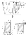
- the lower cover plate 1 and the upper cover plate 2 of the first embodiment have outer surfaces 3 and 4, respectively, which are intended for anchoring to the associated vertebral body. They are preferably flat. But there are also other substantially flat designs including suitable surface structures for better anchoring to the bone conceivable.
- the cover plates are preferably made of metal.
- the lower cover plate 1 applies to the upper cover plate 2 to a flat bottom surface 5, which is bordered on three sides by a collar 6, which forms an inwardly projecting bar 7 above an inner undercut.
- the lower cover plate 1 is oval or rectangular in plan view.
- the bottom surface 5 and the collar 6 of the lower cover plate 1 form a seat for the prosthesis core 10, which consists of lubricious material, such as polyethylene. He has a matching to the bottom surface 5 planar lower surface which is bounded laterally and dorsally by a skirt 11, above which a groove 12 is located.
- the strip 11 engages in the undercut of the collar 6 below the bar 7.
- the bar 7 engages in the groove 12 a.
- the core 10 has on all sides substantially the same outline shape in the plan view as the lower cover plate 1 and the upper cover plate 2. It covers in particular the collar 6, so that the size of the provided from the top of the core sliding surface 22 by the presence of the collar 6 is not reduced.
- the collar 6 may be made small in relation to the height of the core 10. Nevertheless, the core can not escape the gap between the cover plates 1 and 2, because it is prevented by the interaction of the undercut strips 7 and 11 at the lifting of the cover plate 1.
- the cover plates 1, 2 each have an approximately perpendicular projecting from them mounting flange 15, 16, the screw holes 17 for attachment to the vertebral body contains.
- a slot 18 which forms a sliding guide for a stop plate 14 which is slidably held therein. She can do the in Fig. 2 take illustrated blocking position in which it forms a stop for the forward movement of the core 10. It can also be shifted down into the slot 18 or removed altogether from it, that the prosthesis core can be easily inserted from ventral into the seat of the lower cover plate and between the cover plates.
- It contains two holes 19, which are aligned in the blocking position with the screw holes 17.
- the lateral branches of the collar 6 form with their strip 7 in cooperation with the strip 11 and the groove 12 of the core 10, a guide device for the prosthesis core 10, in which this from the open ventral side (in Fig. 2 right) in AP direction (in Fig. 3 indicated) can be inserted.
- the dorsal part 21 of the collar 6 acts as a safety stop, which prevents escape of the core in the dorsal direction from the space between the cover plates 1 and 2.
- the presence of the undercut on the collar 6 and on the edge of the core 10 is important for the guiding function only in the lateral regions 8 and 9 of the lower cover plate 1 and the core 10, but not in the dorsal course 21 of the collar 6.
- the core 10 On the upper side, the core 10 has a preferably convex spherical joint surface 22, which cooperates with the underside, concave-spherical sliding surface 23 of the upper cover plate 2 to form a joint.
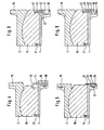
- Fig. 4 a variant in which the prosthesis core 10 ventral (in Fig. 4 right) is a little shorter than the lower cover plate, so that between its ventral end surface 13 and de stop 14 game remains when the prosthesis core is in its widest dorsal position.
- the core 10 can be mounted in the AP direction.
- the upper cover plate 2 pivots in relation to the lower cover plate 1 in the view according to Fig. 4 a little clockwise and at opposite to the stretching movement.
- the degree of movement play in the AP direction is preferably between one and four, more preferably on the order of two to three millimeters, in the case of a cervical prosthesis. If lateral relative movement is intended, their extent should not exceed two millimeters.
- the cover plates 1, 2 each have a right angle projecting from them flange 15, 16 which contains screw holes 17 for attachment to the vertebral body.
- flange 15 of the lower cover plate 1 is centered between two screw holes 17 a stop plate 28 rotatably secured by a head bolt 29.
- the plane in which it can slidably rotate is determined by the front surface of the mounting flange 15, which is therefore referred to as a sliding guide surface.
- the stopper plate has two wings 30 extending substantially to the side and a tongue 31 extending transversely thereto. It is made of resilient metal and is biased so that its wings 30 press against the sliding guide surface.
- a turning tool such as a screwdriver
- it contains a suitable opening or recess 32.
- a suitable opening or recess 32 When in the in Fig. 6 shown mounting position, it does not protrude beyond the bottom surface 5 of the lower cover plate.
- the core 10 can therefore be inserted unhindered into the insertion guide formed by the collar 6. Is it rotated 180 °, as it is in Fig. 5 and 7 is shown, the tongue 31 projects over the surface 5 and thereby forms a stop which prevents the core 10 from leaving the guide to the ventral side.
- tongue 31 of the stop plate 28 and the opposing surface 13 of the core 10 may - as in Fig. 7 indicated - a space of a few millimeters are located.
- the core 10 can move in the guide formed by the lateral sections 8, 9 of the collar 6 by a certain distance in the AP direction (see the description of Fig. 4 ). If this motion play is not desired, the clearance between face 13 and stop 14 is reduced to zero as shown in FIG Fig. 6 is required.
- a slot 40 is cut, which in the in Fig. 10 left half of the flange 15 passes completely from top to bottom and in the right part of the flange 15 of the in Fig. 10 Dashed line 41 is limited.
- the slot 40 opposite a slot 42 aligned with the slot 40 is cut into the bottom of the prosthesis core 10.
- the two slots 40, 42 serve to receive a stop plate 43 whose outline is approximately equal to the boundaries of the space intended for its reception, which is formed by the slots 40, 42. As Fig. 10 shows it can be inserted after insertion of the prosthesis core 10 from the side into the slots 40, 42.
- the stop plate 43 may be provided at the end with a nose 44, which after the complete insertion of the stop plate 43 in the slots 40, 42 on the right side (see Fig. 11 ) and can be bent to secure the stop plate.
- the flange 15 has screw holes 17 which serve to secure the lower cover plate 1 to the associated vertebral body. In the left part (see Fig. 10 ) the screw hole 17 there traverses the slot 40 which extends there over the entire height of the flange 15 to receive the left wide wing 45 of the stop plate.
- This wide wing 45 of the stop plate also includes a screw hole 46 that, when the stop plate 43 is inserted ( Fig. 9 and 11 ) is aligned with the local screw hole 17. If a fixing screw is in this screw hole, the stopper plate 43 can not escape from its securing position.
- the screw hole 46 and the nose 44 form mutually independent securing devices. It is therefore not necessary that always both are provided. If the screw hole 46 is present, the nose 44 may be missing. If the nose is provided, the wide wing 45 of the stop plate below the line 47 and the corresponding part of the slot in the mounting flange 15 may be missing. It then suffices a stop plate above the dash-dot line 47 ( Fig. 12 ) runs. So that the stop plate can not escape to the right from the receiving slot 40, 42 in this case, one of the nose 44 corresponding backup nose (not shown) may also be provided at the left end of the stop plate 43. Upwards, the stop plate 43 can not escape, because it is covered by that part of the prosthesis core 10, which forms the slot 42.
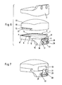
- the fourth embodiment according to FIGS. 13 and 14 illustrates an alternative embodiment of the seat, which is formed on the lower cover plate 1 for the prosthetic core 10.
- the prosthesis consists of a lower cover plate 51 and an upper cover plate 52.
- the lower cover plate has an upper, flat bottom surface 53, on which the prosthesis core 54 rests. While this core is guided at its outer edges in the previously described embodiments, in the fourth embodiment it has a recess 55 with undercut inner edges 56 which cooperate with an elongated projection 57 of the lower cover plate with correspondingly undercut edges 58.
- the core 54 is thereby - as explained with reference to the first embodiment - guided in the AP direction movable relative to the lower cover plate 51. In addition, it is protected by the cooperating undercuts against lifting from the lower cover plate. Not shown stops are provided which prevent the dorsal and ventral slipping out of the prosthesis core from the plate gap.
- the lower cover plate 51 can by the in Fig. 14 illustrated lower cover plate 51a to be replaced, which differs from the lower cover plate 31 in that its projection 57a is not elongated, but is designed circular limited in plan view. This allows the prosthesis core 54, which is believed to be rotationally connected to the upper cover plate 52 with respect to a vertical axis, to rotate about the projection 57a without impeding the desired AP movement. This may be desirable in aspherical design of the sliding surfaces between the core 54 and upper cover plate 52.
Landscapes
- Health & Medical Sciences (AREA)
- Engineering & Computer Science (AREA)
- Biomedical Technology (AREA)
- Neurology (AREA)
- Orthopedic Medicine & Surgery (AREA)
- Cardiology (AREA)
- Oral & Maxillofacial Surgery (AREA)
- Transplantation (AREA)
- Heart & Thoracic Surgery (AREA)
- Vascular Medicine (AREA)
- Life Sciences & Earth Sciences (AREA)
- Animal Behavior & Ethology (AREA)
- General Health & Medical Sciences (AREA)
- Public Health (AREA)
- Veterinary Medicine (AREA)
- Prostheses (AREA)
- Medicines Containing Material From Animals Or Micro-Organisms (AREA)
Priority Applications (1)
| Application Number | Priority Date | Filing Date | Title |
|---|---|---|---|
| EP02782913A EP1482875B1 (de) | 2002-03-12 | 2002-10-15 | Zwischenwirbelprothese |
Applications Claiming Priority (8)
| Application Number | Priority Date | Filing Date | Title |
|---|---|---|---|
| EP02005630A EP1344506A1 (de) | 2002-03-12 | 2002-03-12 | Zwischenwirbelprothese für die Halswirbelsäule |
| EP02005632 | 2002-03-12 | ||
| EP02005632A EP1344508B1 (de) | 2002-03-12 | 2002-03-12 | Zwischenwirbelprothese, insbesondere für die Halswirbelsäule |
| EP02005631A EP1344507A1 (de) | 2002-03-12 | 2002-03-12 | Zwischenwirbelprothese für die Halswirbelsäule |
| EP02005631 | 2002-03-12 | ||
| EP02005630 | 2002-03-12 | ||
| PCT/EP2002/011524 WO2003075803A1 (de) | 2002-03-12 | 2002-10-15 | Zwischenwirbelprothese |
| EP02782913A EP1482875B1 (de) | 2002-03-12 | 2002-10-15 | Zwischenwirbelprothese |
Publications (2)
| Publication Number | Publication Date |
|---|---|
| EP1482875A1 EP1482875A1 (de) | 2004-12-08 |
| EP1482875B1 true EP1482875B1 (de) | 2009-03-11 |
Family
ID=27808292
Family Applications (1)
| Application Number | Title | Priority Date | Filing Date |
|---|---|---|---|
| EP02782913A Expired - Lifetime EP1482875B1 (de) | 2002-03-12 | 2002-10-15 | Zwischenwirbelprothese |
Country Status (15)
| Country | Link |
|---|---|
| EP (1) | EP1482875B1 (https=) |
| JP (1) | JP4243197B2 (https=) |
| KR (1) | KR20050026696A (https=) |
| CN (1) | CN100444813C (https=) |
| AT (1) | ATE424788T1 (https=) |
| AU (2) | AU2002346916B2 (https=) |
| BR (1) | BR0215639A (https=) |
| CA (1) | CA2482403C (https=) |
| DE (1) | DE50213354D1 (https=) |
| ES (1) | ES2322446T3 (https=) |
| IL (2) | IL163649A0 (https=) |
| MX (1) | MXPA04008811A (https=) |
| PL (1) | PL371017A1 (https=) |
| WO (1) | WO2003075803A1 (https=) |
| ZA (1) | ZA200407101B (https=) |
Families Citing this family (45)
| Publication number | Priority date | Publication date | Assignee | Title |
|---|---|---|---|---|
| FR2824261B1 (fr) | 2001-05-04 | 2004-05-28 | Ldr Medical | Prothese de disque intervertebral et procede et outils de mise en place |
| US8388684B2 (en) | 2002-05-23 | 2013-03-05 | Pioneer Signal Technology, Inc. | Artificial disc device |
| US7001433B2 (en) | 2002-05-23 | 2006-02-21 | Pioneer Laboratories, Inc. | Artificial intervertebral disc device |
| US8012212B2 (en) | 2003-04-07 | 2011-09-06 | Nuvasive, Inc. | Cervical intervertebral disk prosthesis |
| DE10330698B4 (de) * | 2003-07-08 | 2005-05-25 | Aesculap Ag & Co. Kg | Zwischenwirbelimplantat |
| DE20310433U1 (de) | 2003-07-08 | 2003-09-04 | Aesculap AG & Co. KG, 78532 Tuttlingen | Chirurgisches Instrument zum Handhaben eines Implantats |
| DE20313183U1 (de) | 2003-08-22 | 2003-10-16 | Aesculap Ag & Co Kg | Zwischenwirbelimplantat |
| JP2007517616A (ja) * | 2004-01-09 | 2007-07-05 | ウォーソー・オーソペディック・インコーポレーテッド | スプリット脊椎デバイスおよび方法 |
| FR2865629B1 (fr) | 2004-02-04 | 2007-01-26 | Ldr Medical | Prothese de disque intervertebral |
| PT1711133E (pt) | 2004-02-04 | 2011-06-01 | Ldr Medical | Prótese de disco intervertebral |
| EP1570813A1 (de) * | 2004-03-05 | 2005-09-07 | Cervitech, Inc. | Zervikale Bandscheibenprothese mit Luxationssicherung und Instrumentarium |
| US7175662B2 (en) * | 2004-04-01 | 2007-02-13 | Cervitech, Inc. | Cervical intervertebral prosthesis |
| DE102004028967B4 (de) | 2004-06-16 | 2006-05-24 | Aesculap Ag & Co. Kg | Zwischenwirbelimplantat |
| ATE524121T1 (de) | 2004-11-24 | 2011-09-15 | Abdou Samy | Vorrichtungen zur platzierung eines orthopädischen intervertebralen implantats |
| FR2879436B1 (fr) | 2004-12-22 | 2007-03-09 | Ldr Medical | Prothese de disque intervertebral |
| FR2887435B1 (fr) * | 2005-06-24 | 2007-10-05 | Abbott Spine Sa | Prothese de disque intervertebral |
| FR2887762B1 (fr) | 2005-06-29 | 2007-10-12 | Ldr Medical Soc Par Actions Si | Instrumentation d'insertion de prothese de disque intervertebral entre des vertebres |
| FR2891135B1 (fr) | 2005-09-23 | 2008-09-12 | Ldr Medical Sarl | Prothese de disque intervertebral |
| FR2893838B1 (fr) | 2005-11-30 | 2008-08-08 | Ldr Medical Soc Par Actions Si | Prothese de disque intervertebral et instrumentation d'insertion de la prothese entre les vertebres |
| US8715350B2 (en) | 2006-09-15 | 2014-05-06 | Pioneer Surgical Technology, Inc. | Systems and methods for securing an implant in intervertebral space |
| EP2063817A4 (en) | 2006-09-15 | 2012-04-18 | Pioneer Surgical Technology Inc | JOINT CARDROPLASTY DEVICE WITH MOVING ELEMENTS |
| US8465546B2 (en) | 2007-02-16 | 2013-06-18 | Ldr Medical | Intervertebral disc prosthesis insertion assemblies |
| FR2916956B1 (fr) | 2007-06-08 | 2012-12-14 | Ldr Medical | Cage intersomatique,prothese intervertebrale,dispositif d'ancrage et instrumentation d'implantation |
| US10821003B2 (en) | 2007-06-20 | 2020-11-03 | 3Spline Sezc | Spinal osteotomy |
| US8764806B2 (en) | 2009-12-07 | 2014-07-01 | Samy Abdou | Devices and methods for minimally invasive spinal stabilization and instrumentation |
| JP5744319B2 (ja) * | 2011-05-18 | 2015-07-08 | ウルリッヒ ゲーエムベーハー ウント コー. カーゲー | 人工器官椎間板 |
| US8845728B1 (en) | 2011-09-23 | 2014-09-30 | Samy Abdou | Spinal fixation devices and methods of use |
| US9241807B2 (en) | 2011-12-23 | 2016-01-26 | Pioneer Surgical Technology, Inc. | Systems and methods for inserting a spinal device |
| US20130226240A1 (en) | 2012-02-22 | 2013-08-29 | Samy Abdou | Spinous process fixation devices and methods of use |
| US9198767B2 (en) | 2012-08-28 | 2015-12-01 | Samy Abdou | Devices and methods for spinal stabilization and instrumentation |
| US9320617B2 (en) | 2012-10-22 | 2016-04-26 | Cogent Spine, LLC | Devices and methods for spinal stabilization and instrumentation |
| KR101397192B1 (ko) * | 2013-12-18 | 2014-05-19 | 윤홍원 | 탄성력을 지닌 추간 인공 디스크 |
| CN105105890A (zh) * | 2015-08-31 | 2015-12-02 | 北京市春立正达医疗器械股份有限公司 | 一种颈椎椎间盘假体 |
| US10857003B1 (en) | 2015-10-14 | 2020-12-08 | Samy Abdou | Devices and methods for vertebral stabilization |
| CN105662661B (zh) * | 2016-02-26 | 2018-02-13 | 邹德威 | 用于脊椎减压的内植物、椎间植骨融合器和人工椎间盘 |
| CN106236332B (zh) * | 2016-08-31 | 2018-07-20 | 北京爱康宜诚医疗器材有限公司 | 椎间盘假体 |
| US10744000B1 (en) | 2016-10-25 | 2020-08-18 | Samy Abdou | Devices and methods for vertebral bone realignment |
| US10973648B1 (en) | 2016-10-25 | 2021-04-13 | Samy Abdou | Devices and methods for vertebral bone realignment |
| HUE055578T2 (hu) * | 2017-02-17 | 2021-12-28 | Inst Nat Sante Rech Med | Temporo-mandibuláris protézis |
| CN107049563B (zh) * | 2017-04-19 | 2020-02-07 | 北京爱康宜诚医疗器材有限公司 | 椎间盘假体 |
| JP7521152B2 (ja) | 2017-09-08 | 2024-07-24 | エクスタント メディカル ホールディングス,インコーポレイテッド. | 椎間インプラント、器具、及び方法 |
| USD907771S1 (en) | 2017-10-09 | 2021-01-12 | Pioneer Surgical Technology, Inc. | Intervertebral implant |
| CN108836579B (zh) * | 2018-07-06 | 2023-07-28 | 北京爱康宜诚医疗器材有限公司 | 人工椎间盘假体 |
| US11179248B2 (en) | 2018-10-02 | 2021-11-23 | Samy Abdou | Devices and methods for spinal implantation |
| US12409046B2 (en) | 2022-04-12 | 2025-09-09 | 3Spine, Inc. | Total spinal joint systems with motion moderators |
Family Cites Families (9)
| Publication number | Priority date | Publication date | Assignee | Title |
|---|---|---|---|---|
| FR2659226B1 (fr) | 1990-03-07 | 1992-05-29 | Jbs Sa | Prothese pour disques intervertebraux et ses instruments d'implantation. |
| US5425773A (en) * | 1992-01-06 | 1995-06-20 | Danek Medical, Inc. | Intervertebral disk arthroplasty device |
| US5676701A (en) * | 1993-01-14 | 1997-10-14 | Smith & Nephew, Inc. | Low wear artificial spinal disc |
| FR2718635B1 (fr) * | 1994-04-15 | 1996-07-05 | Axcyl Medical | Prothèse cervicale. |
| WO1999065412A1 (en) * | 1998-06-18 | 1999-12-23 | Pioneer Laboratories, Inc. | Spinal fixation system |
| DE29814174U1 (de) * | 1998-08-07 | 1999-12-16 | Howmedica GmbH, 24232 Schönkirchen | Instrumentarium für das Einbringen eines Implantats in die menschliche Wirbelsäule |
| US6368350B1 (en) * | 1999-03-11 | 2002-04-09 | Sulzer Spine-Tech Inc. | Intervertebral disc prosthesis and method |
| AU780719B2 (en) * | 1999-07-02 | 2005-04-14 | Spine Solutions Inc. | Intervertebral implant |
| CN2445722Y (zh) * | 2000-09-26 | 2001-09-05 | 沈强 | 一种人颈椎间盘假体 |
-
2002
- 2002-10-15 KR KR1020047014208A patent/KR20050026696A/ko not_active Ceased
- 2002-10-15 EP EP02782913A patent/EP1482875B1/de not_active Expired - Lifetime
- 2002-10-15 WO PCT/EP2002/011524 patent/WO2003075803A1/de not_active Ceased
- 2002-10-15 MX MXPA04008811A patent/MXPA04008811A/es active IP Right Grant
- 2002-10-15 CA CA2482403A patent/CA2482403C/en not_active Expired - Fee Related
- 2002-10-15 JP JP2003574081A patent/JP4243197B2/ja not_active Expired - Fee Related
- 2002-10-15 ES ES02782913T patent/ES2322446T3/es not_active Expired - Lifetime
- 2002-10-15 AU AU2002346916A patent/AU2002346916B2/en not_active Ceased
- 2002-10-15 IL IL16364902A patent/IL163649A0/xx unknown
- 2002-10-15 BR BR0215639-3A patent/BR0215639A/pt not_active IP Right Cessation
- 2002-10-15 CN CNB028285107A patent/CN100444813C/zh not_active Expired - Fee Related
- 2002-10-15 PL PL02371017A patent/PL371017A1/xx unknown
- 2002-10-15 DE DE50213354T patent/DE50213354D1/de not_active Expired - Lifetime
- 2002-10-15 AT AT02782913T patent/ATE424788T1/de not_active IP Right Cessation
-
2004
- 2004-08-19 IL IL163649A patent/IL163649A/en not_active IP Right Cessation
- 2004-09-06 ZA ZA2004/07101A patent/ZA200407101B/en unknown
-
2008
- 2008-10-20 AU AU2008230006A patent/AU2008230006A1/en not_active Abandoned
Also Published As
| Publication number | Publication date |
|---|---|
| ZA200407101B (en) | 2005-08-31 |
| PL371017A1 (en) | 2005-06-13 |
| CN1622793A (zh) | 2005-06-01 |
| IL163649A (en) | 2009-11-18 |
| JP2005526550A (ja) | 2005-09-08 |
| CA2482403C (en) | 2010-08-03 |
| AU2002346916A1 (en) | 2003-09-22 |
| IL163649A0 (en) | 2005-12-18 |
| MXPA04008811A (es) | 2005-07-01 |
| AU2008230006A1 (en) | 2008-11-13 |
| DE50213354D1 (de) | 2009-04-23 |
| AU2002346916B2 (en) | 2008-08-07 |
| KR20050026696A (ko) | 2005-03-15 |
| ATE424788T1 (de) | 2009-03-15 |
| EP1482875A1 (de) | 2004-12-08 |
| CA2482403A1 (en) | 2003-09-18 |
| JP4243197B2 (ja) | 2009-03-25 |
| CN100444813C (zh) | 2008-12-24 |
| WO2003075803A1 (de) | 2003-09-18 |
| ES2322446T3 (es) | 2009-06-22 |
| BR0215639A (pt) | 2004-12-21 |
Similar Documents
| Publication | Publication Date | Title |
|---|---|---|
| EP1482875B1 (de) | Zwischenwirbelprothese | |
| EP1344508B1 (de) | Zwischenwirbelprothese, insbesondere für die Halswirbelsäule | |
| EP1344507A1 (de) | Zwischenwirbelprothese für die Halswirbelsäule | |
| DE69918998T2 (de) | Wirbelsäule-osteosynthesevorrichtung zur vorderen fixierung mittels einer platte | |
| EP1729673B1 (de) | Zervikale zwischenwirbelprothese | |
| DE69833736T2 (de) | Drehbare Gelenkprothese mit axialer Fixierung | |
| EP1624830B1 (de) | Wirbelsäulenimplantat | |
| EP1344506A1 (de) | Zwischenwirbelprothese für die Halswirbelsäule | |
| EP1572037B1 (de) | Zwischenwirbelimplantat mit kippbaren gelenkteilen | |
| DE69918848T2 (de) | Vorderseitenplatte für lendenwirbel und positionierwerkzeug dafür | |
| DE3023353C2 (de) | Zwischenwirbel-Totalprothese | |
| EP0852934B1 (de) | Tibiaplattform für ein künstliches Kniegelenk | |
| EP1504733B1 (de) | Zervikalprothese mit Einsetzinstrument | |
| DE60022367T2 (de) | Bandscheibenprothese mit zähnen auf den seiten | |
| EP0808619B1 (de) | Ellbogengelenk-Endoprothese | |
| DE69915464T2 (de) | Knochenplatte mit mittel zur verriegelung der knochenschrauben | |
| DE60129036T2 (de) | Vorrichtung zur intervertebralen Stabilisierung | |
| EP1389982A1 (de) | System von bandscheibenprothesen | |
| DE9300791U1 (de) | Tibia-Element zum Ersatz einer Knieprothese | |
| EP1737350A1 (de) | Knochenspreizer | |
| DE102007052799A1 (de) | Implantat | |
| EP1841386A1 (de) | Zervikale zwischenwirbelprothesen | |
| EP1417940A1 (de) | Wirbelsäulenprothese | |
| EP1610731A1 (de) | Zervikale bandscheiben-gelenkprothese | |
| DE2901009A1 (de) | Kniegelenk-endoprothese |
Legal Events
| Date | Code | Title | Description |
|---|---|---|---|
| PUAI | Public reference made under article 153(3) epc to a published international application that has entered the european phase |
Free format text: ORIGINAL CODE: 0009012 |
|
| 17P | Request for examination filed |
Effective date: 20040811 |
|
| AK | Designated contracting states |
Kind code of ref document: A1 Designated state(s): AT BE BG CH CY CZ DE DK EE ES FI FR GB GR IE IT LI LU MC NL PT SE SK TR |
|
| AX | Request for extension of the european patent |
Extension state: AL LT LV MK RO SI |
|
| 17Q | First examination report despatched |
Effective date: 20080219 |
|
| GRAP | Despatch of communication of intention to grant a patent |
Free format text: ORIGINAL CODE: EPIDOSNIGR1 |
|
| GRAS | Grant fee paid |
Free format text: ORIGINAL CODE: EPIDOSNIGR3 |
|
| GRAA | (expected) grant |
Free format text: ORIGINAL CODE: 0009210 |
|
| AK | Designated contracting states |
Kind code of ref document: B1 Designated state(s): AT BE BG CH CY CZ DE DK EE ES FI FR GB GR IE IT LI LU MC NL PT SE SK TR |
|
| REG | Reference to a national code |
Ref country code: GB Ref legal event code: FG4D Free format text: NOT ENGLISH |
|
| REG | Reference to a national code |
Ref country code: CH Ref legal event code: EP |
|
| REG | Reference to a national code |
Ref country code: IE Ref legal event code: FG4D Free format text: LANGUAGE OF EP DOCUMENT: GERMAN |
|
| REF | Corresponds to: |
Ref document number: 50213354 Country of ref document: DE Date of ref document: 20090423 Kind code of ref document: P |
|
| REG | Reference to a national code |
Ref country code: ES Ref legal event code: FG2A Ref document number: 2322446 Country of ref document: ES Kind code of ref document: T3 |
|
| REG | Reference to a national code |
Ref country code: SE Ref legal event code: TRGR |
|
| PG25 | Lapsed in a contracting state [announced via postgrant information from national office to epo] |
Ref country code: FI Free format text: LAPSE BECAUSE OF FAILURE TO SUBMIT A TRANSLATION OF THE DESCRIPTION OR TO PAY THE FEE WITHIN THE PRESCRIBED TIME-LIMIT Effective date: 20090311 |
|
| REG | Reference to a national code |
Ref country code: CH Ref legal event code: PFA Owner name: CERVITECH, INC. Free format text: CERVITECH INC.#300 ROUNDHILL DRIVE#ROCKWAY, NJ 07866 (US) -TRANSFER TO- CERVITECH, INC.#C/O NUVASIVE, INC. 7475 LUSK BOULEVARD#SAN DIEGO, CA 92121 (US) |
|
| REG | Reference to a national code |
Ref country code: IE Ref legal event code: FD4D |
|
| PG25 | Lapsed in a contracting state [announced via postgrant information from national office to epo] |
Ref country code: PT Free format text: LAPSE BECAUSE OF FAILURE TO SUBMIT A TRANSLATION OF THE DESCRIPTION OR TO PAY THE FEE WITHIN THE PRESCRIBED TIME-LIMIT Effective date: 20090824 Ref country code: EE Free format text: LAPSE BECAUSE OF FAILURE TO SUBMIT A TRANSLATION OF THE DESCRIPTION OR TO PAY THE FEE WITHIN THE PRESCRIBED TIME-LIMIT Effective date: 20090311 Ref country code: IE Free format text: LAPSE BECAUSE OF FAILURE TO SUBMIT A TRANSLATION OF THE DESCRIPTION OR TO PAY THE FEE WITHIN THE PRESCRIBED TIME-LIMIT Effective date: 20090311 |
|
| PG25 | Lapsed in a contracting state [announced via postgrant information from national office to epo] |
Ref country code: SK Free format text: LAPSE BECAUSE OF FAILURE TO SUBMIT A TRANSLATION OF THE DESCRIPTION OR TO PAY THE FEE WITHIN THE PRESCRIBED TIME-LIMIT Effective date: 20090311 |
|
| PLBE | No opposition filed within time limit |
Free format text: ORIGINAL CODE: 0009261 |
|
| STAA | Information on the status of an ep patent application or granted ep patent |
Free format text: STATUS: NO OPPOSITION FILED WITHIN TIME LIMIT |
|
| PG25 | Lapsed in a contracting state [announced via postgrant information from national office to epo] |
Ref country code: BG Free format text: LAPSE BECAUSE OF FAILURE TO SUBMIT A TRANSLATION OF THE DESCRIPTION OR TO PAY THE FEE WITHIN THE PRESCRIBED TIME-LIMIT Effective date: 20090611 Ref country code: DK Free format text: LAPSE BECAUSE OF FAILURE TO SUBMIT A TRANSLATION OF THE DESCRIPTION OR TO PAY THE FEE WITHIN THE PRESCRIBED TIME-LIMIT Effective date: 20090311 |
|
| PGFP | Annual fee paid to national office [announced via postgrant information from national office to epo] |
Ref country code: AT Payment date: 20091022 Year of fee payment: 8 Ref country code: CH Payment date: 20091026 Year of fee payment: 8 Ref country code: CZ Payment date: 20091013 Year of fee payment: 8 Ref country code: ES Payment date: 20091026 Year of fee payment: 8 Ref country code: SE Payment date: 20091023 Year of fee payment: 8 |
|
| 26N | No opposition filed |
Effective date: 20091214 |
|
| PGFP | Annual fee paid to national office [announced via postgrant information from national office to epo] |
Ref country code: NL Payment date: 20091027 Year of fee payment: 8 |
|
| PGFP | Annual fee paid to national office [announced via postgrant information from national office to epo] |
Ref country code: IT Payment date: 20091023 Year of fee payment: 8 |
|
| PG25 | Lapsed in a contracting state [announced via postgrant information from national office to epo] |
Ref country code: MC Free format text: LAPSE BECAUSE OF NON-PAYMENT OF DUE FEES Effective date: 20091031 |
|
| PGFP | Annual fee paid to national office [announced via postgrant information from national office to epo] |
Ref country code: BE Payment date: 20091029 Year of fee payment: 8 |
|
| REG | Reference to a national code |
Ref country code: FR Ref legal event code: CA |
|
| PG25 | Lapsed in a contracting state [announced via postgrant information from national office to epo] |
Ref country code: GR Free format text: LAPSE BECAUSE OF FAILURE TO SUBMIT A TRANSLATION OF THE DESCRIPTION OR TO PAY THE FEE WITHIN THE PRESCRIBED TIME-LIMIT Effective date: 20090612 |
|
| PG25 | Lapsed in a contracting state [announced via postgrant information from national office to epo] |
Ref country code: LU Free format text: LAPSE BECAUSE OF NON-PAYMENT OF DUE FEES Effective date: 20091015 |
|
| BERE | Be: lapsed |
Owner name: CERVITECH INC. Effective date: 20101031 |
|
| REG | Reference to a national code |
Ref country code: NL Ref legal event code: V1 Effective date: 20110501 |
|
| REG | Reference to a national code |
Ref country code: CH Ref legal event code: PL |
|
| PG25 | Lapsed in a contracting state [announced via postgrant information from national office to epo] |
Ref country code: CH Free format text: LAPSE BECAUSE OF NON-PAYMENT OF DUE FEES Effective date: 20101031 Ref country code: CZ Free format text: LAPSE BECAUSE OF NON-PAYMENT OF DUE FEES Effective date: 20101015 Ref country code: LI Free format text: LAPSE BECAUSE OF NON-PAYMENT OF DUE FEES Effective date: 20101031 |
|
| PG25 | Lapsed in a contracting state [announced via postgrant information from national office to epo] |
Ref country code: NL Free format text: LAPSE BECAUSE OF NON-PAYMENT OF DUE FEES Effective date: 20110501 Ref country code: TR Free format text: LAPSE BECAUSE OF FAILURE TO SUBMIT A TRANSLATION OF THE DESCRIPTION OR TO PAY THE FEE WITHIN THE PRESCRIBED TIME-LIMIT Effective date: 20090311 Ref country code: AT Free format text: LAPSE BECAUSE OF NON-PAYMENT OF DUE FEES Effective date: 20101015 Ref country code: BE Free format text: LAPSE BECAUSE OF NON-PAYMENT OF DUE FEES Effective date: 20101031 |
|
| PG25 | Lapsed in a contracting state [announced via postgrant information from national office to epo] |
Ref country code: CY Free format text: LAPSE BECAUSE OF FAILURE TO SUBMIT A TRANSLATION OF THE DESCRIPTION OR TO PAY THE FEE WITHIN THE PRESCRIBED TIME-LIMIT Effective date: 20090311 Ref country code: SE Free format text: LAPSE BECAUSE OF NON-PAYMENT OF DUE FEES Effective date: 20101016 |
|
| REG | Reference to a national code |
Ref country code: ES Ref legal event code: FD2A Effective date: 20111118 |
|
| PG25 | Lapsed in a contracting state [announced via postgrant information from national office to epo] |
Ref country code: IT Free format text: LAPSE BECAUSE OF NON-PAYMENT OF DUE FEES Effective date: 20101015 |
|
| PG25 | Lapsed in a contracting state [announced via postgrant information from national office to epo] |
Ref country code: ES Free format text: LAPSE BECAUSE OF NON-PAYMENT OF DUE FEES Effective date: 20101016 |
|
| PGFP | Annual fee paid to national office [announced via postgrant information from national office to epo] |
Ref country code: FR Payment date: 20131018 Year of fee payment: 12 Ref country code: DE Payment date: 20131024 Year of fee payment: 12 |
|
| REG | Reference to a national code |
Ref country code: DE Ref legal event code: R119 Ref document number: 50213354 Country of ref document: DE |
|
| PG25 | Lapsed in a contracting state [announced via postgrant information from national office to epo] |
Ref country code: DE Free format text: LAPSE BECAUSE OF NON-PAYMENT OF DUE FEES Effective date: 20150501 |
|
| REG | Reference to a national code |
Ref country code: FR Ref legal event code: ST Effective date: 20150630 |
|
| PG25 | Lapsed in a contracting state [announced via postgrant information from national office to epo] |
Ref country code: FR Free format text: LAPSE BECAUSE OF NON-PAYMENT OF DUE FEES Effective date: 20141031 |
|
| PGFP | Annual fee paid to national office [announced via postgrant information from national office to epo] |
Ref country code: GB Payment date: 20210922 Year of fee payment: 20 |
|
| REG | Reference to a national code |
Ref country code: GB Ref legal event code: PE20 Expiry date: 20221014 |
|
| PG25 | Lapsed in a contracting state [announced via postgrant information from national office to epo] |
Ref country code: GB Free format text: LAPSE BECAUSE OF EXPIRATION OF PROTECTION Effective date: 20221014 |