EP1482292B1 - Pistolet de distribution avec capteur de fuites d'hydrogène integré - Google Patents
Pistolet de distribution avec capteur de fuites d'hydrogène integré Download PDFInfo
- Publication number
- EP1482292B1 EP1482292B1 EP04012781.3A EP04012781A EP1482292B1 EP 1482292 B1 EP1482292 B1 EP 1482292B1 EP 04012781 A EP04012781 A EP 04012781A EP 1482292 B1 EP1482292 B1 EP 1482292B1
- Authority
- EP
- European Patent Office
- Prior art keywords
- nozzle
- hydrogen
- sensor
- oxygen
- sensors
- Prior art date
- Legal status (The legal status is an assumption and is not a legal conclusion. Google has not performed a legal analysis and makes no representation as to the accuracy of the status listed.)
- Expired - Lifetime
Links
- UFHFLCQGNIYNRP-UHFFFAOYSA-N Hydrogen Chemical compound [H][H] UFHFLCQGNIYNRP-UHFFFAOYSA-N 0.000 title claims description 184
- 239000001257 hydrogen Substances 0.000 title claims description 169
- 229910052739 hydrogen Inorganic materials 0.000 title claims description 169
- 238000012546 transfer Methods 0.000 claims description 59
- QVGXLLKOCUKJST-UHFFFAOYSA-N atomic oxygen Chemical compound [O] QVGXLLKOCUKJST-UHFFFAOYSA-N 0.000 claims description 56
- 239000001301 oxygen Substances 0.000 claims description 56
- 229910052760 oxygen Inorganic materials 0.000 claims description 56
- 239000007788 liquid Substances 0.000 claims description 48
- 150000002431 hydrogen Chemical class 0.000 claims description 27
- 238000000034 method Methods 0.000 claims description 26
- 230000008878 coupling Effects 0.000 claims description 16
- 238000010168 coupling process Methods 0.000 claims description 16
- 238000005859 coupling reaction Methods 0.000 claims description 16
- PXHVJJICTQNCMI-UHFFFAOYSA-N nickel Substances [Ni] PXHVJJICTQNCMI-UHFFFAOYSA-N 0.000 claims description 10
- 229910052759 nickel Inorganic materials 0.000 claims description 6
- 230000005669 field effect Effects 0.000 claims description 5
- 230000000977 initiatory effect Effects 0.000 claims description 5
- 230000003213 activating effect Effects 0.000 claims description 4
- 238000010926 purge Methods 0.000 claims description 3
- 230000001419 dependent effect Effects 0.000 claims 1
- 239000007789 gas Substances 0.000 description 36
- 239000011324 bead Substances 0.000 description 17
- 238000012544 monitoring process Methods 0.000 description 13
- 238000003860 storage Methods 0.000 description 12
- 238000005516 engineering process Methods 0.000 description 9
- VNWKTOKETHGBQD-UHFFFAOYSA-N methane Chemical compound C VNWKTOKETHGBQD-UHFFFAOYSA-N 0.000 description 8
- BASFCYQUMIYNBI-UHFFFAOYSA-N platinum Chemical compound [Pt] BASFCYQUMIYNBI-UHFFFAOYSA-N 0.000 description 8
- KDLHZDBZIXYQEI-UHFFFAOYSA-N Palladium Chemical compound [Pd] KDLHZDBZIXYQEI-UHFFFAOYSA-N 0.000 description 7
- 230000007246 mechanism Effects 0.000 description 7
- 239000003570 air Substances 0.000 description 6
- 238000001514 detection method Methods 0.000 description 6
- 239000000463 material Substances 0.000 description 6
- 239000003054 catalyst Substances 0.000 description 5
- 239000000126 substance Substances 0.000 description 5
- 230000008859 change Effects 0.000 description 4
- 238000010276 construction Methods 0.000 description 4
- 238000010586 diagram Methods 0.000 description 4
- 229910044991 metal oxide Inorganic materials 0.000 description 4
- 150000004706 metal oxides Chemical class 0.000 description 4
- 239000012071 phase Substances 0.000 description 4
- 229910052697 platinum Inorganic materials 0.000 description 4
- 230000008569 process Effects 0.000 description 4
- 239000010409 thin film Substances 0.000 description 4
- QMMFVYPAHWMCMS-UHFFFAOYSA-N Dimethyl sulfide Chemical compound CSC QMMFVYPAHWMCMS-UHFFFAOYSA-N 0.000 description 3
- 230000009471 action Effects 0.000 description 3
- 239000012080 ambient air Substances 0.000 description 3
- 230000003197 catalytic effect Effects 0.000 description 3
- 238000005259 measurement Methods 0.000 description 3
- VLKZOEOYAKHREP-UHFFFAOYSA-N n-Hexane Chemical compound CCCCCC VLKZOEOYAKHREP-UHFFFAOYSA-N 0.000 description 3
- 239000003345 natural gas Substances 0.000 description 3
- 230000003287 optical effect Effects 0.000 description 3
- 230000004044 response Effects 0.000 description 3
- 239000004065 semiconductor Substances 0.000 description 3
- -1 >10%) be present Chemical compound 0.000 description 2
- IJGRMHOSHXDMSA-UHFFFAOYSA-N Atomic nitrogen Chemical compound N#N IJGRMHOSHXDMSA-UHFFFAOYSA-N 0.000 description 2
- LSDPWZHWYPCBBB-UHFFFAOYSA-N Methanethiol Chemical compound SC LSDPWZHWYPCBBB-UHFFFAOYSA-N 0.000 description 2
- 238000013459 approach Methods 0.000 description 2
- 238000006243 chemical reaction Methods 0.000 description 2
- 230000000694 effects Effects 0.000 description 2
- 230000005611 electricity Effects 0.000 description 2
- 239000003792 electrolyte Substances 0.000 description 2
- 239000002360 explosive Substances 0.000 description 2
- 239000000446 fuel Substances 0.000 description 2
- 239000002828 fuel tank Substances 0.000 description 2
- 238000007254 oxidation reaction Methods 0.000 description 2
- 229910052763 palladium Inorganic materials 0.000 description 2
- 238000012545 processing Methods 0.000 description 2
- SUVIGLJNEAMWEG-UHFFFAOYSA-N propane-1-thiol Chemical compound CCCS SUVIGLJNEAMWEG-UHFFFAOYSA-N 0.000 description 2
- KJRCEJOSASVSRA-UHFFFAOYSA-N propane-2-thiol Chemical compound CC(C)S KJRCEJOSASVSRA-UHFFFAOYSA-N 0.000 description 2
- 229920006395 saturated elastomer Polymers 0.000 description 2
- 238000009738 saturating Methods 0.000 description 2
- 239000000758 substrate Substances 0.000 description 2
- OKTJSMMVPCPJKN-UHFFFAOYSA-N Carbon Chemical compound [C] OKTJSMMVPCPJKN-UHFFFAOYSA-N 0.000 description 1
- UGFAIRIUMAVXCW-UHFFFAOYSA-N Carbon monoxide Chemical compound [O+]#[C-] UGFAIRIUMAVXCW-UHFFFAOYSA-N 0.000 description 1
- OTMSDBZUPAUEDD-UHFFFAOYSA-N Ethane Chemical compound CC OTMSDBZUPAUEDD-UHFFFAOYSA-N 0.000 description 1
- 241000321453 Paranthias colonus Species 0.000 description 1
- VYPSYNLAJGMNEJ-UHFFFAOYSA-N Silicium dioxide Chemical compound O=[Si]=O VYPSYNLAJGMNEJ-UHFFFAOYSA-N 0.000 description 1
- XUIMIQQOPSSXEZ-UHFFFAOYSA-N Silicon Chemical compound [Si] XUIMIQQOPSSXEZ-UHFFFAOYSA-N 0.000 description 1
- 230000004913 activation Effects 0.000 description 1
- 238000005275 alloying Methods 0.000 description 1
- 230000015572 biosynthetic process Effects 0.000 description 1
- 239000003990 capacitor Substances 0.000 description 1
- 229910052799 carbon Inorganic materials 0.000 description 1
- 229910002091 carbon monoxide Inorganic materials 0.000 description 1
- 238000007084 catalytic combustion reaction Methods 0.000 description 1
- 239000000919 ceramic Substances 0.000 description 1
- 239000003610 charcoal Substances 0.000 description 1
- 238000001311 chemical methods and process Methods 0.000 description 1
- 239000011248 coating agent Substances 0.000 description 1
- 238000000576 coating method Methods 0.000 description 1
- 150000001875 compounds Chemical class 0.000 description 1
- 238000009833 condensation Methods 0.000 description 1
- 230000005494 condensation Effects 0.000 description 1
- 238000001816 cooling Methods 0.000 description 1
- 230000007423 decrease Effects 0.000 description 1
- 230000003247 decreasing effect Effects 0.000 description 1
- 238000013461 design Methods 0.000 description 1
- XYWDPYKBIRQXQS-UHFFFAOYSA-N di-isopropyl sulphide Natural products CC(C)SC(C)C XYWDPYKBIRQXQS-UHFFFAOYSA-N 0.000 description 1
- 238000003891 environmental analysis Methods 0.000 description 1
- 230000007613 environmental effect Effects 0.000 description 1
- 230000005284 excitation Effects 0.000 description 1
- 238000007710 freezing Methods 0.000 description 1
- 230000008014 freezing Effects 0.000 description 1
- 229930195733 hydrocarbon Natural products 0.000 description 1
- 150000002430 hydrocarbons Chemical class 0.000 description 1
- 125000004435 hydrogen atom Chemical group [H]* 0.000 description 1
- 230000007062 hydrolysis Effects 0.000 description 1
- 238000006460 hydrolysis reaction Methods 0.000 description 1
- 230000002401 inhibitory effect Effects 0.000 description 1
- 239000007791 liquid phase Substances 0.000 description 1
- 238000012423 maintenance Methods 0.000 description 1
- 238000004519 manufacturing process Methods 0.000 description 1
- 229910052751 metal Inorganic materials 0.000 description 1
- 239000002184 metal Substances 0.000 description 1
- WXEHBUMAEPOYKP-UHFFFAOYSA-N methylsulfanylethane Chemical compound CCSC WXEHBUMAEPOYKP-UHFFFAOYSA-N 0.000 description 1
- 238000002156 mixing Methods 0.000 description 1
- 239000000203 mixture Substances 0.000 description 1
- 229910052757 nitrogen Inorganic materials 0.000 description 1
- 230000036961 partial effect Effects 0.000 description 1
- 238000002360 preparation method Methods 0.000 description 1
- 230000001681 protective effect Effects 0.000 description 1
- 230000000630 rising effect Effects 0.000 description 1
- 238000007789 sealing Methods 0.000 description 1
- 230000035945 sensitivity Effects 0.000 description 1
- 229910052710 silicon Inorganic materials 0.000 description 1
- 239000010703 silicon Substances 0.000 description 1
- 229910052814 silicon oxide Inorganic materials 0.000 description 1
- 241000894007 species Species 0.000 description 1
- WMXCDAVJEZZYLT-UHFFFAOYSA-N tert-butylthiol Chemical compound CC(C)(C)S WMXCDAVJEZZYLT-UHFFFAOYSA-N 0.000 description 1
- 231100000331 toxic Toxicity 0.000 description 1
- 230000002588 toxic effect Effects 0.000 description 1
- 230000007704 transition Effects 0.000 description 1
- 238000011144 upstream manufacturing Methods 0.000 description 1
- 238000010792 warming Methods 0.000 description 1
- XLYOFNOQVPJJNP-UHFFFAOYSA-N water Substances O XLYOFNOQVPJJNP-UHFFFAOYSA-N 0.000 description 1
- 238000004804 winding Methods 0.000 description 1
Images




Classifications
-
- F—MECHANICAL ENGINEERING; LIGHTING; HEATING; WEAPONS; BLASTING
- F02—COMBUSTION ENGINES; HOT-GAS OR COMBUSTION-PRODUCT ENGINE PLANTS
- F02M—SUPPLYING COMBUSTION ENGINES IN GENERAL WITH COMBUSTIBLE MIXTURES OR CONSTITUENTS THEREOF
- F02M21/00—Apparatus for supplying engines with non-liquid fuels, e.g. gaseous fuels stored in liquid form
- F02M21/02—Apparatus for supplying engines with non-liquid fuels, e.g. gaseous fuels stored in liquid form for gaseous fuels
- F02M21/0218—Details on the gaseous fuel supply system, e.g. tanks, valves, pipes, pumps, rails, injectors or mixers
- F02M21/0221—Fuel storage reservoirs, e.g. cryogenic tanks
-
- F—MECHANICAL ENGINEERING; LIGHTING; HEATING; WEAPONS; BLASTING
- F02—COMBUSTION ENGINES; HOT-GAS OR COMBUSTION-PRODUCT ENGINE PLANTS
- F02D—CONTROLLING COMBUSTION ENGINES
- F02D19/00—Controlling engines characterised by their use of non-liquid fuels, pluralities of fuels, or non-fuel substances added to the combustible mixtures
- F02D19/02—Controlling engines characterised by their use of non-liquid fuels, pluralities of fuels, or non-fuel substances added to the combustible mixtures peculiar to engines working with gaseous fuels
- F02D19/026—Measuring or estimating parameters related to the fuel supply system
- F02D19/029—Determining density, viscosity, concentration or composition
-
- F—MECHANICAL ENGINEERING; LIGHTING; HEATING; WEAPONS; BLASTING
- F02—COMBUSTION ENGINES; HOT-GAS OR COMBUSTION-PRODUCT ENGINE PLANTS
- F02M—SUPPLYING COMBUSTION ENGINES IN GENERAL WITH COMBUSTIBLE MIXTURES OR CONSTITUENTS THEREOF
- F02M21/00—Apparatus for supplying engines with non-liquid fuels, e.g. gaseous fuels stored in liquid form
- F02M21/02—Apparatus for supplying engines with non-liquid fuels, e.g. gaseous fuels stored in liquid form for gaseous fuels
- F02M21/0203—Apparatus for supplying engines with non-liquid fuels, e.g. gaseous fuels stored in liquid form for gaseous fuels characterised by the type of gaseous fuel
- F02M21/0206—Non-hydrocarbon fuels, e.g. hydrogen, ammonia or carbon monoxide
-
- F—MECHANICAL ENGINEERING; LIGHTING; HEATING; WEAPONS; BLASTING
- F02—COMBUSTION ENGINES; HOT-GAS OR COMBUSTION-PRODUCT ENGINE PLANTS
- F02M—SUPPLYING COMBUSTION ENGINES IN GENERAL WITH COMBUSTIBLE MIXTURES OR CONSTITUENTS THEREOF
- F02M21/00—Apparatus for supplying engines with non-liquid fuels, e.g. gaseous fuels stored in liquid form
- F02M21/02—Apparatus for supplying engines with non-liquid fuels, e.g. gaseous fuels stored in liquid form for gaseous fuels
- F02M21/0218—Details on the gaseous fuel supply system, e.g. tanks, valves, pipes, pumps, rails, injectors or mixers
- F02M21/0293—Safety devices; Fail-safe measures
-
- F—MECHANICAL ENGINEERING; LIGHTING; HEATING; WEAPONS; BLASTING
- F17—STORING OR DISTRIBUTING GASES OR LIQUIDS
- F17C—VESSELS FOR CONTAINING OR STORING COMPRESSED, LIQUEFIED OR SOLIDIFIED GASES; FIXED-CAPACITY GAS-HOLDERS; FILLING VESSELS WITH, OR DISCHARGING FROM VESSELS, COMPRESSED, LIQUEFIED, OR SOLIDIFIED GASES
- F17C2205/00—Vessel construction, in particular mounting arrangements, attachments or identifications means
- F17C2205/03—Fluid connections, filters, valves, closure means or other attachments
- F17C2205/0302—Fittings, valves, filters, or components in connection with the gas storage device
- F17C2205/037—Quick connecting means, e.g. couplings
-
- Y—GENERAL TAGGING OF NEW TECHNOLOGICAL DEVELOPMENTS; GENERAL TAGGING OF CROSS-SECTIONAL TECHNOLOGIES SPANNING OVER SEVERAL SECTIONS OF THE IPC; TECHNICAL SUBJECTS COVERED BY FORMER USPC CROSS-REFERENCE ART COLLECTIONS [XRACs] AND DIGESTS
- Y02—TECHNOLOGIES OR APPLICATIONS FOR MITIGATION OR ADAPTATION AGAINST CLIMATE CHANGE
- Y02E—REDUCTION OF GREENHOUSE GAS [GHG] EMISSIONS, RELATED TO ENERGY GENERATION, TRANSMISSION OR DISTRIBUTION
- Y02E60/00—Enabling technologies; Technologies with a potential or indirect contribution to GHG emissions mitigation
- Y02E60/30—Hydrogen technology
- Y02E60/32—Hydrogen storage
-
- Y—GENERAL TAGGING OF NEW TECHNOLOGICAL DEVELOPMENTS; GENERAL TAGGING OF CROSS-SECTIONAL TECHNOLOGIES SPANNING OVER SEVERAL SECTIONS OF THE IPC; TECHNICAL SUBJECTS COVERED BY FORMER USPC CROSS-REFERENCE ART COLLECTIONS [XRACs] AND DIGESTS
- Y02—TECHNOLOGIES OR APPLICATIONS FOR MITIGATION OR ADAPTATION AGAINST CLIMATE CHANGE
- Y02P—CLIMATE CHANGE MITIGATION TECHNOLOGIES IN THE PRODUCTION OR PROCESSING OF GOODS
- Y02P90/00—Enabling technologies with a potential contribution to greenhouse gas [GHG] emissions mitigation
- Y02P90/45—Hydrogen technologies in production processes
-
- Y—GENERAL TAGGING OF NEW TECHNOLOGICAL DEVELOPMENTS; GENERAL TAGGING OF CROSS-SECTIONAL TECHNOLOGIES SPANNING OVER SEVERAL SECTIONS OF THE IPC; TECHNICAL SUBJECTS COVERED BY FORMER USPC CROSS-REFERENCE ART COLLECTIONS [XRACs] AND DIGESTS
- Y02—TECHNOLOGIES OR APPLICATIONS FOR MITIGATION OR ADAPTATION AGAINST CLIMATE CHANGE
- Y02T—CLIMATE CHANGE MITIGATION TECHNOLOGIES RELATED TO TRANSPORTATION
- Y02T10/00—Road transport of goods or passengers
- Y02T10/10—Internal combustion engine [ICE] based vehicles
- Y02T10/30—Use of alternative fuels, e.g. biofuels
Definitions
- the present invention relates generally to chemical detection and more particularly to an apparatus and process for the measurement of hydrogen, a flammable material, when the hydrogen is being transferred from one storage container to another storage container.
- a mercaptan e.g., tertiary butyl mercaptan, isopropyl mercaptan, normal propyl mercaptan, dimethyl sulfide mercaptan, and methyl ethyl sulfide
- a mercaptan e.g., tertiary butyl mercaptan, isopropyl mercaptan, normal propyl mercaptan, dimethyl sulfide mercaptan, and methyl ethyl sulfide
- thermal conductivity sensors may pose an "ignition source” problem that can ignite leaking hydrogen, when the hydrogen concentration is greater than about 4% per volume; electrochemical and MOS technologies require the presence of oxygen to operate; optical sensors cannot get wet or be exposed to a wet environment and therefore must typically be used in a clean and dry environment.
- CGI combustible gas indicator
- Mine Safety Appliances Co. of Pittsburgh, PA combustible gas indicator
- the CGI is one of the most widely used instruments to provide a warning to safety responders when flammable substances in the atmosphere begin to approach their explosive limits. Most fire departments and industrial facilities have such instruments.
- the CGI is a non-specific detector that detects flammable gases in the atmosphere. Its operation is based upon the catalytic combustion of the flammable gas on a filament in a detector known as a "Wheatstone Bridge".
- the CGI is calibrated with a flammable gas (e.g., hexane) using a known concentration referenced to NIST (National Institute of Standard Technology).
- a flammable gas e.g., hexane
- NIST National Institute of Standard Technology
- the burning of this known concentration of the calibrant gas on the filament produces a signal, which is directly proportional to this specified concentration of the calibrant gas.
- the detection of a different flammable gas produces a signal that can be related to the response of the calibrant gas by pre-determined "response factors" that are provided by the manufacturer of the instrument.
- this approach cannot be used within the fueling nozzle because of its mode of operation, because its hot wire-filament, can cause an unsafe condition, by generating a spark source.
- the flammable detection means requires substantial amounts of oxygen (e.g., >10%) be present, best applied to metal oxide semiconductor (MOS) sensor technology. This is also not acceptable because mixing air, or oxygen, with hydrogen (i.e., 4% - 74% hydrogen in air or 4% - 90% hydrogen in oxygen) in the presence of an ignition source (e.g., at least 0.02 millijoules), results in a dangerous condition.
- MOS-based sensors as primary information providers are widely used in many fields of technology and industry for environmental analysis. The most ardent problems of MOS-based sensor manufacturing are the reproduction of resistive properties and possibility of the formation of thin film metal oxide sensitive layers in certain configurations.
- a catalytic bead sensor which also requires the presence of oxygen.
- This type of sensor is made from two separate elements or “beads" that surround a wire operating at a high temperature (approximately 450°C).
- a first element, the active element is made by winding a small coil of wire, sealing it in a ceramic substance, and then coating it with a catalyst to promote a reaction with the gas.
- the second element, the reference element is made identical to the active element except in place of the catalyst, a passivating substance is used to prevent this bead from reacting with the gas molecules.
- the reference bead compensates for changes in ambient temperature, humidity, and pressure variations.
- the beads are generally placed in separate legs of a Wheatstone bridge circuit.
- gas comes into the environment, it has no effect on the passivated bead, but has a significant effect (primarily in terms of temperature) on the catalyzed bead.
- the increase in heat increases the resistance; the difference between the readings of the wires in the two beads forms the sensor signal.
- catalytic bead sensors operate above a threshold or "turn-on" voltage corresponding to the bead temperature that can, in the presence of the catalyst and oxygen, first ignite the gas.
- the catalyst slowly deactivates on the bead.
- the threshold voltage gradually increases, and the sensor sensitivity decreases.
- changes in the wire coil cause increased zero drift and noise.
- the sensor must be replaced.
- a mixture of combustible gas or vapor in air diffuses through the sensor flame arrestor, it oxidizes on the catalytically-treated sensing bead. Since this oxidation reaction is exothermic, it causes an increase in the temperature of this bead (in relationship to the temperature of the reference bead) and a resulting increase in the electrical resistance of a small platinum coil embedded in this bead.
- the change in resistance in the embedded platinum coil is proportional to the amount of chemical energy released by the oxidation reaction.
- Electronic circuitry e.g., a transmitter immediately detects this increase in resistance and reduces electrical power to the bead until the original platinum coil resistance is restored. The amount of electrical power removed is linearly proportional to the combustible gas concentration present.
- Electrochemical sensors utilize a technology similar to fuel cells.
- Fuel cells consist of an electrolyte with an anode on one side and a cathode on the other. They create electricity by passing a gas (usually hydrogen) over the anode and oxygen over the cathode. The two electrodes are separated by an electrolyte. This produces electricity, water, and heat.
- Electrochemical sensors work the same way. The gas passing over the electrode creates a chemical reaction and electrical current. The current generated is proportional to the amount of gas in the cell. In order for these to work, there must be oxygen on the other side of the cell.
- a first embodiment of the invention relates to a nozzle for dispensing hydrogen gas from a hydrogen gas source into a container and for detecting hydrogen gas leaks, as defined in claim 1.
- a second embodiment of the invention relates to a method for detecting hydrogen gas leaks during the transfer of hydrogen gas from a hydrogen gas source into a container according to claim 12.
- a third embodiment of the invention relates to a nozzle for use in a transfer system for dispensing liquid hydrogen from a liquid hydrogen source into a container and for detecting the undesirable entry of oxygen into the system according to claim 20.
- a fourth embodiment of the invention relates to a method for detecting the undesirable entry of oxygen into a transfer system that transfers liquid hydrogen from a liquid hydrogen source into a container according to claim 21.
- the present invention provides an apparatus and method according to claims 1, 12, 20 and 21 for accurately measuring the hydrogen concentration within a hydrogen fueling nozzle during transfer of hydrogen from one storage container to another storage container and automatically alerting and/or safely controlling such transfer as required.
- the first container 1 may comprise any supply source such as a pressure vessel (wherein a pressure vessel is defined as a closed container capable of withstanding internal pressure greater than ambient pressure, and in as used in this Specification, typically less than 900 atmospheres), or hydrogen generator such as a hydrolysis unit or a reformer, a gas compressor, or a liquid hydrogen pump.
- the second container 2 may comprise a pressure vessel.
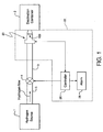
- this fueling nozzle 20 forms part of a monitoring and control system 22 that also comprises a controller 26 and alarm 28.
- the fueling nozzle 20 informs, via the use of molecular sensors 100 internal to the nozzle housing, the controller 26 of the absolute concentration of the hydrogen in transit and the controller 26 can activate a series of alarms 28, if necessary, and can even stop the flow of the hydrogen, where required, by controlling, e.g., a transfer valve 4.
- the molecular sensors 100 emit a signal indicative of the current concentration of hydrogen to the controller 26.
- the term “internal” means “within or on the nozzle” and excludes any location off of the outside surface of the nozzle. To that end, as will be discussed in detail below, the term “internal” includes any and all locations inside or on the nozzle such as but not limited to the normal flow path of the hydrogen gas through the nozzle, the walls of the nozzle, seals in the nozzle, shafts, valves, shrouds, rings, etc. that form any portion of the nozzle.
- the preferred embodiment of the fueling nozzle 20 is for use with hydrogen gas transfer.
- a fueling nozzle also using internal sensors, for transferring liquid hydrogen from one container to another container; the discussion of such a fueling nozzle for transferring liquid hydrogen will be discussed later.
- Fig. 3 shows a cross-sectional view of the nozzle 20 of the present invention which comprises a typical high pressure gas nozzle 202 ( Fig. 2 ) that includes internal hydrogen gas sensors 100, and whereby the normal flow path (NFP) of the hydrogen gas is shown.
- these hydrogen sensors 100 are positioned internal to the gas nozzle 202, not external to the nozzle housing.
- the high pressure gas nozzle 202 ( Fig. 2 ) is shown by way of example only and that any high pressure gas nozzle 202 could be used.
- the exemplary gas nozzle 202 depicted in Fig. 2 comprises a "double block and bleed nozzle" construction having an input 204, an output 206, a vent 208, and a control handle 210.
- the internal hydrogen gas sensors 100 are positioned at locations within the nozzle housing 202 that may be prone to leaks, i.e., locations having a seal, seat and/or O-ring.
- the sensors 100 can accurately detect the absolute concentration of hydrogen gas at these internal locations and therefore permit the monitoring and control system 22 to automatically respond (when necessary) to these detected levels.
- all of these sensors 100 are positioned in the nozzle 20 for ease of maintenance/removal.
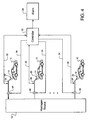
- a hydrogen fueling station is depicted using a plurality of these fueling nozzles 20 which include these internal hydrogen gas sensors 100 (hereinafter "IHG sensors 100").
- Each fueling nozzle 20 is coupled to a common hydrogen source 1A via respective control valves 4A.
- Each IHG sensor 100 is independently coupled to the controller 26 for providing an electrical signal from each sensor 100 in the nozzle 20 representing the respective hydrogen concentration detected, as well as for providing excitation (e.g., 24VDC) to the sensor 100.
- a wire harness 32 represents all of the signal/power cabling from each of IHG sensors 100 to the controller 26 for each nozzle 20.
- a control cable 34 is coupled between the controller 26 and each control valve 4A that allows the controller 26 to shutdown a particular hydrogen transfer, if necessary.
- Vehicles 10 (or other destination hydrogen containers) can be then be positioned adjacent a corresponding a fueling nozzle 20.
- the nozzle output 206 is adapted for coupling and effecting a tight seal to a fueling port 14 of the vehicle's hydrogen tank 2A.
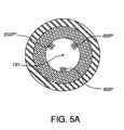
- the fueling nozzle 20 can be coupled to the fueling port 14 in any position rotated around its axis 101 ( Fig. 3 ), it is possible that an IHG sensor, e.g., IHG sensor 202P, could be temporarily located at an elevation beneath the hydrogen gas leak point, thereby resulting in that leak being undetected by IHG sensor 202P. To prevent this from occurring, it may be necessary to position three IHG sensors around that particular location within the nozzle 20. For example, as shown in Fig. 5A , three IHG sensors, namely, IHG sensor 202P, 202P' and 202P" are displaced 120o around the inside circumference of the shroud 100P.
- Fig. 6 depicts a typical hydrogen fueling process over time based on IHG sensor 100P at the nozzle shroud 202P which surrounds the nozzle output 206.
- IHG sensor 100P should only be detecting background hydrogen levels (BHL; see Fig. 6 ); this is defined as the pre-fueling stage, t PF .
- BHL background hydrogen levels
- IHG sensor 100P begins detecting the hydrogen concentration emitted from the fueling port 14 itself which causes the detected hydrogen concentration level to spike, during this nozzle coupling period, t NC .
- the fueling period, t F begins when the operator manipulates the handle 210 wherein hydrogen gas is delivered to the vehicle fuel tank 2A.
- the pressure increases and some hydrogen may leak around the seal which is detected by the IHG sensor 100P, which is indicated by the slowly rising hydrogen concentration shown in Fig. 4 .
- the operator de-couples the nozzle 20 (t ND ) which causes the detected hydrogen level to spike.
- any finite amount of hydrogen gas released then dissipates; as a result, as shown in Fig. 6 , during this "after fueling" period, t AF , the IHG sensor 100P detects this decreasing hydrogen concentration level which returns to the BHL.
- these sensors 100 In order to accurately account for hydrogen leaks in a closed environment (e.g., low oxygen content) with high precision, these sensors 100 must:
- a hydrogen gas sensor that can achieve these performance characteristics is presently sold under the tradename ROBUST HYDROGEN SENSOR TM by H2SCAN, LLC of Valencia, California.
- the H2SCAN sensor utilizes a two-part hydrogen-detection mechanism that permits the sensor to detect hydrogen concentrations over a broad range while remaining exclusively selective to hydrogen.
- the H2SCAN sensor is an ASIC (application specific integrated circuit) comprising a hydrogen-sensing field effect transistor 104 (FET- also referred to as a MOS or MIS (metal-insulator-semiconductor) transistor/capacitor) for detecting low levels of hydrogen (e.g., 1ppm-5000ppm) and a palladium-nickel (Pd-Ni) chemiresistor 102 for detecting high levels of hydrogen (e.g., 2500ppm-1x10 6 ppm).
- FET- field effect transistor
- MOS or MIS metal-insulator-semiconductor
- Pd-Ni palladium-nickel
- each of these two hydrogen-detecting mechanisms 102/104 can be temperature-compensated and pressure-compensated by respective on-board circuitries 106/108.
- the construction and operation of the H2SCAN sensor is set forth in U.S. Patent No. 5,279,795 (Hughes et al. ) whose entire disclosure is incorporated by reference herein.
- Sandia National Laboratories Report SAND2000-8248, June 2000, entitled "A Small Form Factor Solid-State Hydrogen Sensor Package" by S.E. Fass and G.R. Dulleck provides further details about the H2SCAN sensor design and operation.
- This H2SCAN sensor structure is unique in that only hydrogen atoms can diffuse into the sensor material to trigger the changes in electrical behavior, i.e., the H2SCAN sensor is selective for hydrogen. Alloying palladium with nickel prevents phase transitions in the thin films at high H 2 overpressures, making this sensor suitable for chemical process conditions.
- the sensor entitled “The DCH Robust Hydrogen Sensor TM ", the sensor:
- the hydrogen-sensing FET 104/Pd-Ni chemiresistor 102 can continue to accurately detect hydrogen concentrations (e.g., 2500ppm-1x10 6 ppm), whereas other conventional hydrogen sensors would otherwise saturate.
- This last feature is important because by not saturating, the H2SCAN sensor can continue to provide accurate hydrogen concentration levels to the controller 26; this uniquely allows the controller 26 to allow hydrogen transfer in those lines still operating safely while taking appropriate action (setting an alarm, shutting down a particular transfer, etc.) for transfers that have reached a first safety level (e.g., 10,000 ppm), thereby avoiding a "worst case scenario" by implementing an across-the-board shutdown of all transfers; in contrast, because conventional hydrogen sensors saturate at the first safety level, those monitoring systems must implement the worst case scenario action and shutdown all transfers.
- a first safety level e.g. 10,000 ppm
- the IHG sensors 100 (100B-100P) located at internal nozzle locations 202B-202P require only the Pd-Ni chemiresistor 102 while the IHG sensor 100 (100A) at location 202A (a coupling location between the nozzle 20 and the transfer line 3A) requires only the hydrogen-sensing FET 104.
- These particular hydrogen-detecting mechanisms are established based on the conditions at these nozzle locations.
- the hydrogen-sensing FET 104 would be quickly saturated and no longer provide an accurate measurement of the absolute hydrogen concentration.
- IHG sensor 100 (100A) at nozzle location 202A which forms one of the most leak-tight points in the fueling system, hydrogen concentration levels at all times during the fueling process remain in the low range (e.g., 1ppm-5000ppm) where the hydrogen-sensing FET 104 accurately operates and to which the Pd-Ni chemiresistor 102 could not accurately detect.
- each IHG sensor 100 may comprise a H2SCAN sensor with one of the two hydrogen-detecting mechanisms being activated, or in the alternative, may comprise a new ASIC having only one of the two hydrogen-detecting mechanisms thereon (i.e., Pd-Ni chemiresistor 102 or the hydrogen-sensing FET 104) along with the temperature-compensation circuitry 106 and the pressure compensation circuitry 108.
- An example of a sensor that comprises only the hydrogen-sensing FET is sensor model no. AS-FHH-400, or sensor model no. AS-FHH-450, both manufactured by AppliedSensor of Linköping, Sweden.
- the IHG sensor 1000 in the protection sleeve 2020 is the only IHG sensor 100 that detects the hydrogen level in the immediate outside physical environment. This sensor is recessed inside the protective sleeve 2020 to prevent any damage to the sensor during use.
- Each of the IHG sensors 100 is continuously reporting hydrogen concentration levels to the controller 26.
- the controller 26 checks the data from each IHG sensor 100 to see if there is a 10% or greater change in hydrogen concentration level from the last reading, which is indicative of a possible leak.
- the monitoring and control system 22 operates on safety limits which are in turn based on the lower explosive limit (LEL) of hydrogen in ambient air.
- LEL lower explosive limit
- hydrogen is a flammable gas that can be ignited in ambient air at minimum concentration of 40,000ppm or 4 volume%, i.e., the LEL of hydrogen in ambient air.
- the first safety level is defined as 10,000ppm or 25%LEL (also referred to as 1 volume%).
- a second safety limit is 20,000ppm or 50%LEL.
- the monitoring and control system 22 takes action via the controller 26 activating the alarm 28 and/or controlling the shutoff valves 4A.
- this sensor typically operates in atmospheric pressure (e.g., 0.8 - 1.2 bars) in the temperature range of -40°C to 85°C.
- the hydrogen concentration level detected by this sensor 100O is within the "background hydrogen level-open air (BHL-OA)", e.g., 50-250 ppm v/v (with an error of approximately ⁇ 5ppm), the operating condition is "normal".
- BHL-OA background hydrogen level-open air
- a leak can be manifested in several ways as detected by the IHG sensor 100O:
- the processor 26 In processing this sensor's signals, the processor 26:
- these sensors typically operate in atmospheric pressure (e.g., 0.8 - 1.2 bars) in the temperature range of -40°C to 85°C.
- atmospheric pressure e.g., 0.8 - 1.2 bars
- the hydrogen concentration level detected by these sensors 100A-100N and 100P is within the "background hydrogen level-inside nozzle (BHL-IN)", e.g., 50-5000 ppm v/v (with an error of approximately ⁇ 5ppm)
- the operating condition is "normal".
- a leak can be manifested in several ways as detected by these IHG sensors 100A-100N and 100P:
- the processor 26 In processing these sensors' signals, the processor 26:
- a nozzle for transferring liquid hydrogen is shown in Fig. 8 , which is similar to the nozzle disclosed in European Patent Application EP 0574 811 entitled "Method for Cooling a Storage Container'.
- a hydrogen source tank 1 B is connected to the input side of the nozzle housing 302 through a pump 401, a cryogenic check valve 403 and a vacuum-insulated hose 3B.
- the distal end 303 of the nozzle housing 302 comprises a cryogenic shut-off member 308.
- the distal end 303 of the nozzle housing 302 couples to a coupling port 314 which comprises a coupling socket 305 whose distal end 307 also comprises a cryogenic shut-off member 315.
- a coupling port 314 which comprises a coupling socket 305 whose distal end 307 also comprises a cryogenic shut-off member 315.
- the output side of the coupling socket 305 is coupled to an opening in the storage container 2B via another vacuum-insulated hose 5B.
- the controller 26 also controls the operation of the cryogenic valve 403 and pump 401.
- the open end of a line-terminating tube 333 is slidably (the double-headed arrow 309 indicates the possible movement of the line-terminating tube 333) and concentrically-positioned within the input end of the nozzle housing 302 of the nozzle 320; the other end of the line-terminating tube 333 is coupled to the vacuum-insulated hose 3B.
- the line-terminating tube 333 comprises an output 306 for delivering liquid hydrogen and a projection 334, the purpose of which is discussed below.
- a relief line or vent stack 6A and cryogenic check valve 6B are coupled to the vacuum-insulated hose 3B.
- Each of the shut-off members 308/315 comprises a bore 313 and 317 that permit the line-terminating tube 333 to pass therethrough.
- An output line 416 of the storage container 2B includes a heat exchanger 416 for warming the stored liquid hydrogen before use.
- the methodology in detecting leaks is different.
- the transfer of liquid hydrogen involves only low pressures and the temperature during transfer of the liquid hydrogen is extremely low, e.g., approximately -252.8°C.
- the nozzle 320 comprises 100% hydrogen.
- any of the cryogenic components e.g., the shut-off members 406/408, may begin to leak, thereby allowing allow air to enter, possibly resulting in either oxygen or nitrogen freezing in the storage container 2B.
- an oxygen sensor 400 is positioned inside the nozzle 320, preferably in the line-terminating tube 333, or alternatively, upstream of the liquid hydrogen flow; e.g., in the vacuum-insulated hose 3B.
- the oxygen sensor 400 (e.g., Microsens' MSGS MGSM3000 O 2 monosensor) provides a signal to the controller 26 representative of the oxygen concentration level that it is detecting when the liquid hydrogen is not flowing. Because of the extreme cold temperature of the liquid hydrogen flow, the oxygen sensor 400 does not communicate with the controller 26 while liquid hydrogen is flowing; instead, the oxygen sensor 400 provides a signal to the controller 26 representative of the oxygen concentration level that it is detecting before the liquid hydrogen begins to flow and then after the flow has stopped.
- the controller 26 representative of the oxygen concentration level that it is detecting before the liquid hydrogen begins to flow and then after the flow has stopped.
- the sensor 400 If the sensor 400 detects any oxygen in the nozzle 320 prior to initiating the liquid hydrogen flow, the sensor 400 informs the controller 26 about this detected oxygen level and the controller 26 activates the alarm 28, prevents a transfer system operator (or, if automated, a transfer controller, not shown) from initiating the liquid hydrogen transfer (e.g., by inhibiting the activation of cryogenic valve 403 and pump 404) and institutes an auto-purge phase to drive out the oxygen. Once the oxygen sensor 400 no longer detects any oxygen in the transfer system, the alarm 28 is de-activated and the transfer system is enabled to begin liquid hydrogen transfer.
- a transfer system operator or, if automated, a transfer controller, not shown
- the sensor 400 can begin again detecting for any oxygen that may have entered the flow path and thereby warn the controller 26 to auto-purge the flow path (as well as set the alarm 28 and prevent the transfer system operator, or transfer controller, from initiating another liquid hydrogen transfer) in preparation for the next liquid hydrogen transfer. If there is no oxygen detected, the controller 26 enables the next transfer of liquid hydrogen.
- the oxygen sensor 400 (e.g., Microsens' MSGS 3000 monosensor) used therein may comprise a MOS-type construction wherein a metal oxide layer is doped with metal catalyst and covered with a charcoal/carbon filter to allow for selectivity of oxygen and to reduce cross interference.
- the sensor is deposited on platinum and insulated on a SiO x substrate. This construction can operate in extreme temperatures when working under a gas-to-liquid phase of hydrogen.
- the oxygen sensor 400 must be able to recover, after being exposed to -252.8°C of the NFP of the liquid hydrogen for approximately 2-10 minutes and must respond to the gas phase of oxygen.
- the oxygen sensor 400 can detect the oxygen concentration at the start of the liquid hydrogen transfer and then again at the end of the transfer, when the gas phase condition has returned.
Landscapes
- Engineering & Computer Science (AREA)
- Chemical & Material Sciences (AREA)
- Combustion & Propulsion (AREA)
- Mechanical Engineering (AREA)
- General Engineering & Computer Science (AREA)
- Chemical Kinetics & Catalysis (AREA)
- General Chemical & Material Sciences (AREA)
- Oil, Petroleum & Natural Gas (AREA)
- Investigating Or Analyzing Materials By The Use Of Electric Means (AREA)
- Filling Or Discharging Of Gas Storage Vessels (AREA)
- Examining Or Testing Airtightness (AREA)
Claims (25)
- Pistolet (20) de distribution de gaz d'hydrogène provenant d'une source de gaz d'hydrogène (1A) dans un récipient et de détection de fuites de gaz d'hydrogène, ledit pistolet comprenant :un logement (202) présentant une sortie de pistolet (206) qui est adaptée pour apporter un joint étanche sur une ouverture du récipient ; etau moins un capteur qui est positionné à l'intérieur dudit pistolet, ledit capteur détectant la concentration en hydrogène (100) et émettant un signal indiquant la concentration en hydrogène.
- Pistolet selon la revendication 1, dans lequel ledit au moins un capteur détecte uniquement l'hydrogène et fonctionne lorsqu'un endroit est dépourvu d'oxygène.
- Pistolet selon la revendication 2, dans lequel ledit au moins un capteur comprend une résistance chimique (chemiresistor) au palladium - nickel.
- Pistolet selon la revendication 2, dans lequel ledit au moins un capteur comprend un transistor à effet de champ détectant l'hydrogène.
- Pistolet selon la revendication 2, dans lequel ledit au moins un capteur comprend une pluralité de capteurs, chacun d'eux détectant uniquement l'hydrogène et fonctionnant lorsqu'un endroit est dépourvu d'oxygène, chacun desdits capteurs émettant un signal respectif indiquant la concentration en hydrogène qu'il détecte, chacun de ladite pluralité de capteurs étant positionné au niveau d'un emplacement respectif à l'intérieur dudit pistolet.
- Pistolet selon la revendication 5, dans lequel chacun de ladite pluralité de capteurs comprend une résistance chimique au palladium - nickel.
- Pistolet selon la revendication 5, dans lequel chacun de ladite pluralité de capteurs comprend une résistance chimique au palladium - nickel et un transistor à effet de champ détectant l'hydrogène, ledit résistance chimique ou ledit transistor à effet de champ étant actif selon ledit emplacement respectif dudit capteur.
- Pistolet selon la revendication 5, comprenant une enveloppe entourant une sortie dudit pistolet et dans lequel l'un de ladite pluralité de capteurs est positionné au niveau de ladite enveloppe.
- Pistolet selon la revendication 5, dans lequel l'un de ladite pluralité de capteurs est positionné à l'intérieur d'une paroi dudit pistolet pour détecter les concentrations en hydrogène à l'air libre à proximité immédiate dudit pistolet.
- Pistolet selon la revendication 5, incluant une position de couplage entre ledit pistolet et une ligne de transfert provenant de la source de gaz d'hydrogène, et dans lequel l'un de ladite pluralité de capteurs est positionné à l'intérieur dudit pistolet au niveau de ladite position de couplage.
- Pistolet selon la revendication 10, dans lequel ledit un capteur de ladite pluralité de capteurs qui est positionné à l'intérieur dudit pistolet au niveau de ladite position de couplage, comprend un transistor à effet de champ détectant l'hydrogène.
- Procédé de détection de fuites de gaz d'hydrogène au cours d'un transfert de gaz d'hydrogène provenant d'une source de gaz d'hydrogène dans un récipient, ledit procédé comprenant les étapes consistant à :fournir un pistolet (20), couplé au niveau d'une extrémité à une ligne de transfert provenant de la source de gaz d'hydrogène, et présentant une sortie au niveau de son autre extrémité ;positionner au moins un capteur à l'intérieur dudit pistolet, ledit au moins un capteur émettant un signal indiquant la concentration en hydrogène (100) qu'il détecte tandis que l'hydrogène est transféré ;coupler ledit au moins un capteur à un dispositif de commande (26), ledit dispositif de commande recevant ledit signal indiquant la concentration en hydrogène ;apporter un joint étanche entre ladite extrémité de sortie dudit pistolet et une ouverture du récipient ;amorcer le transfert de gaz d'hydrogène à partir de la source de gaz d'hydrogène dans le récipient ; etavertir un opérateur ou arrêter le transfert de gaz d'hydrogène, à l'aide dudit dispositif de commande, lorsque ledit dispositif de commande détermine que ledit signal reçu a atteint ou dépasse une concentration en hydrogène prédéterminée.
- Procédé selon la revendication 12, dans lequel ladite étape consistant à positionner au moins un capteur à l'intérieur dudit pistolet, comprend le positionnement d'au moins un capteur à l'intérieur dudit pistolet, qui détecte uniquement l'hydrogène et fonctionne lorsqu'un endroit est dépourvu d'oxygène.
- Procédé selon la revendication 13, dans lequel ladite étape consistant à avertir un opérateur ou à arrêter le transfert de gaz d'hydrogène comprend les étapes consistant à :coupler ledit dispositif de commande à une soupape de commande couplée entre la ligne de transfert et ledit pistolet ; etarrêter automatiquement le transfert de gaz d'hydrogène à l'aide dudit dispositif de commande en activant ladite soupape de commande une fois que ladite concentration en hydrogène prédéterminée est atteinte ou dépassée.
- Procédé selon la revendication 11, dans lequel ladite étape consistant à positionner au moins un capteur à l'intérieur dudit pistolet comprend :la localisation d'une pluralité de capteurs à l'intérieur dudit pistolet à des emplacements respectifs à l'intérieur de celui-ci ; etle couplage de chacun de ladite pluralité de capteurs audit dispositif de commande de sorte que ledit dispositif de commande reçoit un signal respectif indiquant la concentration en hydrogène détectée par chacun desdits capteurs.
- Procédé selon la revendication 15, dans lequel ladite étape consistant à localiser une pluralité de capteurs à l'intérieur dudit pistolet à des emplacements respectifs situés à l'intérieur de celui-ci, comprend le positionnement d'une pluralité de capteurs à l'intérieur dudit pistolet, et dans lequel chacun de ladite pluralité de capteurs détecte uniquement l'hydrogène et fonctionne lorsqu'un endroit est dépourvu d'oxygène.
- Procédé selon la revendication 16, dans lequel ladite étape consistant à localiser une pluralité de capteurs à l'intérieur dudit pistolet, comprend la localisation d'un capteur au niveau d'une enveloppe qui entoure une sortie dudit pistolet.
- Procédé selon la revendication 16, dans lequel ladite étape consistant à localiser une pluralité de capteurs à l'intérieur dudit pistolet, comprend la localisation d'un capteur à l'intérieur d'une paroi dudit pistolet de façon à détecter une concentration en hydrogène à l'air libre à proximité immédiate dudit pistolet.
- Procédé selon la revendication 16, dans lequel ladite étape consistant à localiser une pluralité de capteurs à l'intérieur dudit pistolet, comprend la localisation d'un capteur au niveau d'un emplacement de couplage situé entre ledit pistolet et une ligne de transfert provenant de ladite source de gaz d'hydrogène.
- Pistolet (20) destiné à être utilisé dans un système de transfert pour distribuer de l'hydrogène liquide à partir d'une source d'hydrogène liquide (1A) dans un récipient, et détecter une entrée indésirable d'oxygène dans le système, ledit pistolet comprenant :un logement présentant une sortie de pistolet (206) qui est adaptée pour apporter un joint étanche sur une ouverture du récipient ; etun capteur d'oxygène (400), positionné à l'intérieur dudit pistolet, pour détecter la concentration en oxygène lorsque l'hydrogène liquide ne circule pas, ledit capteur émettant un signal indiquant la concentration en oxygène, dans lequel ledit capteur d'oxygène est positionné à l'intérieur dudit pistolet de sorte qu'il soit exposé à un chemin d'écoulement normal de l'hydrogène liquide.
- Procédé de détection d'une entrée indésirable d'oxygène dans un système de transfert qui transfère de l'hydrogène liquide à partir d'une source d'hydrogène liquide dans un récipient, ledit procédé comprenant les étapes consistant à :fournir un pistolet (20), couplé au niveau d'une extrémité à une ligne de transfert provenant de la source d'hydrogène liquide (1A), et présentant une sortie au niveau de son autre extrémité ;positionner un capteur d'oxygène (400) à l'intérieur dudit pistolet et coupler ledit capteur à un dispositif de commande ;dans lequel ledit capteur d'oxygène est positionné à l'intérieur dudit pistolet de sorte qu'il soit exposé à un chemin d'écoulement normal de l'hydrogène liquide ;apporter un joint étanche entre ladite extrémité de sortie dudit pistolet et une ouverture du récipient ;émettre un signal, à l'aide dudit capteur d'oxygène, indiquant la concentration en oxygène dans le système de transfert avant que l'hydrogène liquide ne commence à être transféré, ledit signal étant reçu par ledit dispositif de commande ; etempêcher le transfert d'hydrogène liquide jusqu'à ce que l'oxygène soit éliminé du système de transfert.
- Procédé selon la revendication 21, comprenant en outre une étape selon laquelle ledit dispositif de commande active une phase de purge automatique pour expulser l'oxygène du système.
- Procédé selon la revendication 21, comprenant en outre une étape selon laquelle ledit dispositif de commande active une alarme afin d'avertir un opérateur du système de transfert.
- Procédé selon la revendication 22, comprenant en outre une étape consistant à permettre le transfert d'hydrogène liquide dès que ledit capteur d'oxygène ne détecte plus d'oxygène.
- Procédé selon la revendication 24, dans lequel, une fois que le volume souhaité d'hydrogène liquide a été transféré et que l'écoulement d'hydrogène liquide est terminé, ledit procédé comprend en outre les étapes consistant à :émettre un signal, à l'aide dudit capteur d'oxygène, indiquant la concentration en oxygène dans le système de transfert, ledit signal étant reçu par ledit dispositif de commande ; etempêcher le transfert d'hydrogène liquide jusqu'à ce que l'oxygène soit éliminé du système de transfert.
Applications Claiming Priority (2)
| Application Number | Priority Date | Filing Date | Title |
|---|---|---|---|
| US452549 | 1982-12-23 | ||
| US10/452,549 US7028724B2 (en) | 2003-05-30 | 2003-05-30 | Fueling nozzle with integral molecular leak sensor |
Publications (3)
| Publication Number | Publication Date |
|---|---|
| EP1482292A2 EP1482292A2 (fr) | 2004-12-01 |
| EP1482292A3 EP1482292A3 (fr) | 2012-03-28 |
| EP1482292B1 true EP1482292B1 (fr) | 2014-05-07 |
Family
ID=33131656
Family Applications (1)
| Application Number | Title | Priority Date | Filing Date |
|---|---|---|---|
| EP04012781.3A Expired - Lifetime EP1482292B1 (fr) | 2003-05-30 | 2004-05-28 | Pistolet de distribution avec capteur de fuites d'hydrogène integré |
Country Status (3)
| Country | Link |
|---|---|
| US (2) | US7028724B2 (fr) |
| EP (1) | EP1482292B1 (fr) |
| CA (1) | CA2468291C (fr) |
Cited By (4)
| Publication number | Priority date | Publication date | Assignee | Title |
|---|---|---|---|---|
| WO2017124051A1 (fr) * | 2016-01-16 | 2017-07-20 | Mcnicholas Daniel | Système et procédé de sécurité pour véhicule à gaz naturel comprimé |
| US9919663B2 (en) | 2012-05-03 | 2018-03-20 | Daniel McNicholas | Compressed natural gas vehicle safety system and method |
| US10040680B2 (en) | 2012-05-03 | 2018-08-07 | Daniel McNicholas | Compressed natural gas vehicle safety system and method |
| US10500954B2 (en) | 2012-05-03 | 2019-12-10 | Daniel McNicholas | Compressed natural gas vehicle safety system and method |
Families Citing this family (46)
| Publication number | Priority date | Publication date | Assignee | Title |
|---|---|---|---|---|
| DE50210311D1 (de) * | 2002-04-10 | 2007-07-26 | Sfc Smart Fuel Cell Ag | Adapter als Alternative für eine Brennstoffpatrone |
| WO2004066415A2 (fr) * | 2003-01-23 | 2004-08-05 | The Penn State Research Foundation | Membranes semi-permeables en couche mince pour detecteurs de gaz et applications catalytiques |
| US7568507B2 (en) * | 2005-12-06 | 2009-08-04 | Air Products And Chemicals, Inc. | Diagnostic method and apparatus for a pressurized gas supply system |
| US20070246512A1 (en) * | 2006-04-20 | 2007-10-25 | Shahabudin Kazi | Use of tunable diode lasers for controlling a brazing processes |
| US8020589B2 (en) * | 2007-01-04 | 2011-09-20 | Air Products And Chemicals, Inc. | Hydrogen dispensing station and method of operating the same |
| US7841228B2 (en) * | 2007-02-05 | 2010-11-30 | Toyota Motor Engineering & Manufacturing North America, Inc. | Method of detecting hydrogen sensor saturation in a hydrogen powered fuel cell |
| US20100083581A1 (en) * | 2007-06-18 | 2010-04-08 | Mattice Douglas A | Environmental brush seal |
| JP4311486B2 (ja) * | 2007-09-25 | 2009-08-12 | トヨタ自動車株式会社 | ガス燃料車両 |
| CN102037349A (zh) * | 2008-04-06 | 2011-04-27 | H2Scan公司 | 用于应用催化金属的固态气体传感器的保护涂层 |
| US7780764B2 (en) | 2008-06-27 | 2010-08-24 | Praxair Technology, Inc. | Methods and systems for helium recovery |
| US8615360B2 (en) * | 2009-10-30 | 2013-12-24 | Telenav, Inc. | Navigation system with single selection mileage single capture mechanism and method of operation thereof |
| DE102010048982B4 (de) * | 2010-09-03 | 2022-06-09 | Inficon Gmbh | Lecksuchgerät |
| US8812179B1 (en) * | 2010-10-05 | 2014-08-19 | The Boeing Company | Ammonia detection |
| US8973624B2 (en) * | 2011-01-27 | 2015-03-10 | GM Global Technology Operations LLC | Compressed hydrogen fueling control valve |
| US9458004B2 (en) * | 2011-02-01 | 2016-10-04 | GM Global Technology Operations LLC | Fueling nozzle for gaseous fuels with integrated means for gas detection |
| US9291114B2 (en) * | 2013-02-28 | 2016-03-22 | Briggs & Stratton Corporation | Generator including a fuel shutoff valve |
| JP6189693B2 (ja) * | 2013-09-26 | 2017-08-30 | トヨタ自動車株式会社 | 燃料電池搭載車両 |
| FR3034836B1 (fr) * | 2015-04-10 | 2017-12-01 | Air Liquide | Station et procede de remplissage d'un reservoir avec un gaz carburant |
| CA2982830A1 (fr) * | 2015-04-24 | 2016-10-27 | Cmd Corporation | Procede et appareil servant a des fins de distribution de carburant gazeux a un vehicule |
| US10773822B2 (en) * | 2016-05-29 | 2020-09-15 | Neoex Systems, Inc. | System and method for the transfer of cryogenic fluids |
| JP6516207B2 (ja) * | 2016-11-16 | 2019-05-22 | 株式会社タツノ | 充填装置 |
| JP6558643B2 (ja) * | 2016-11-16 | 2019-08-14 | 株式会社タツノ | 充填装置 |
| US10365665B2 (en) | 2017-01-17 | 2019-07-30 | Rodney Laible | Automatic detection system for detecting disruptions in the flow to a dispensing apparatus |
| US10279942B1 (en) * | 2017-01-17 | 2019-05-07 | Rodney Laible | Automatic detection system for detecting disruptions in the flow to a dispensing apparatus |
| JP6575825B2 (ja) * | 2017-07-11 | 2019-09-18 | 株式会社タツノ | 充填装置 |
| US11331019B2 (en) | 2017-08-07 | 2022-05-17 | The Research Foundation For The State University Of New York | Nanoparticle sensor having a nanofibrous membrane scaffold |
| CN107941860A (zh) * | 2017-11-10 | 2018-04-20 | 中国人民解放军陆军防化学院 | 气体发生装置、配气装置及气体检测装置 |
| CN111684198B (zh) * | 2018-02-09 | 2022-09-23 | 株式会社龙野 | 填充装置 |
| US20220180733A1 (en) * | 2020-01-10 | 2022-06-09 | Daniel McNicholas | Vapor displacement refueling including data communications |
| US12011989B1 (en) | 2021-01-17 | 2024-06-18 | Neoex Systems, Inc. | Direct liquefaction for vehicle refueling |
| CN115723634B (zh) * | 2021-08-27 | 2025-05-30 | 宇通客车股份有限公司 | 一种燃料电池车辆及其加氢口故障检测方法及系统 |
| US20230137335A1 (en) | 2021-10-29 | 2023-05-04 | Air Products And Chemicals, Inc. | Hydrogen storage and dispensing apparatus and method |
| CN114229779B (zh) * | 2021-12-17 | 2024-07-26 | 深圳迎凯生物科技有限公司 | 进液机构、进液方法及体外诊断分析仪 |
| US11998649B2 (en) | 2022-02-24 | 2024-06-04 | Jvis-Usa, Llc | Antimicrobial, push button switch assembly for use at a self-service, dispensing or charging station |
| US12092093B2 (en) | 2022-03-08 | 2024-09-17 | Air Products And Chemicals, Inc. | Apparatus and method for cryogenic pump cooldown |
| CN114383038B (zh) * | 2022-03-24 | 2022-05-24 | 四川凯德源科技有限公司 | 一种氢能汽车加氢充装用机械手臂 |
| SE545827C2 (en) * | 2022-05-13 | 2024-02-13 | Dover Fueling Solutions Uk Ltd | A gas dispenser with a gas sensor |
| US11946599B2 (en) | 2022-06-08 | 2024-04-02 | Air Products And Chemicals, Inc. | Apparatus and method for hydrogen fuel dispensing |
| US20240353066A1 (en) | 2023-04-20 | 2024-10-24 | Air Products And Chemicals, Inc. | Apparatus and Method for Dispensing a Cryogenic Fluid |
| US12129165B1 (en) * | 2023-04-26 | 2024-10-29 | Air Products And Chemicals, Inc. | Apparatus and method for fuel dispensing nozzle maintenance or vehicle battery recharging nozzle maintenance |
| US20250075858A1 (en) | 2023-08-30 | 2025-03-06 | Air Products And Chemicals, Inc. | Apparatus and process for cryogenic liquid vaporization to re-cool gas for cryogenic fluid recovery |
| US20250075455A1 (en) | 2023-08-30 | 2025-03-06 | Air Products And Chemicals, Inc. | Apparatus and process for fog mitigation |
| US20250130554A1 (en) | 2023-10-24 | 2025-04-24 | Air Products And Chemicals, Inc. | Apparatus and process for controlling a display for fuel dispensing |
| US12497936B2 (en) | 2023-11-20 | 2025-12-16 | Air Products And Chemicals, Inc. | Apparatus and process for cooling pressurized gas for fueling |
| US20250332910A1 (en) | 2024-04-24 | 2025-10-30 | Air Products And Chemicals, Inc. | Apparatus, control system and process for rapid fuel dispensing |
| US12613010B2 (en) | 2024-04-24 | 2026-04-28 | Air Products And Chemicals, Inc. | Apparatus, control system and process for rapid fuel dispensing |
Family Cites Families (14)
| Publication number | Priority date | Publication date | Assignee | Title |
|---|---|---|---|---|
| US4782302A (en) * | 1986-10-31 | 1988-11-01 | The United States Of America As Represented By The United States Department Of Energy | Detector and energy analyzer for energetic-hydrogen in beams and plasmas |
| US5012672A (en) * | 1987-09-03 | 1991-05-07 | The United States Of America As Represented By The United States Department Of Energy | Hydrogen gas sensor and method of manufacture |
| US5279795A (en) * | 1993-01-04 | 1994-01-18 | The United States Of America As Represented By The United States Department Of Energy | Extended range chemical sensing apparatus |
| JPH09292491A (ja) * | 1996-04-26 | 1997-11-11 | Hitachi Ltd | 可燃性ガス濃度低減装置及びその制御方法 |
| US5932797A (en) * | 1996-05-08 | 1999-08-03 | Southeastern Universities Research Assn. | Sensitive hydrogen leak detector |
| JP4278181B2 (ja) * | 1996-11-01 | 2009-06-10 | ビーピー オイル インターナショナル リミテッド | 検査装置と使用方法 |
| US5834627A (en) * | 1996-12-17 | 1998-11-10 | Sandia Corporation | Calorimetric gas sensor |
| ATE444481T1 (de) * | 1998-11-16 | 2009-10-15 | California Inst Of Techn | Gleichzeitige bestimmung von gleichgewichts- und kinetischen eigenschaften |
| US6293137B1 (en) * | 2000-05-04 | 2001-09-25 | National Science Council | Hydrogen sensor |
| US6223789B1 (en) * | 1999-06-24 | 2001-05-01 | Tokheim Corporation | Regulation of vapor pump valve |
| US6418983B1 (en) * | 1999-11-17 | 2002-07-16 | Gilbasco Inc. | Vapor flow and hydrocarbon concentration sensor for improved vapor recovery in fuel dispensers |
| DE10044786A1 (de) * | 2000-09-11 | 2002-04-04 | Emitec Emissionstechnologie | Brennstoffzellenanlage und Verfahren zum Betreiben einer Brennstoffzellenanlage |
| CA2472027A1 (fr) * | 2002-01-10 | 2003-07-24 | Matthew A. Harper | Station-service distribuant de l'hydrogene |
| US6755225B1 (en) * | 2003-01-24 | 2004-06-29 | Quantum Fuel Systems Technologies Worldwide, Inc. | Transportable hydrogen refueling station |
-
2003
- 2003-05-30 US US10/452,549 patent/US7028724B2/en not_active Expired - Fee Related
-
2004
- 2004-05-25 CA CA002468291A patent/CA2468291C/fr not_active Expired - Fee Related
- 2004-05-28 EP EP04012781.3A patent/EP1482292B1/fr not_active Expired - Lifetime
-
2006
- 2006-02-06 US US11/347,924 patent/US7191805B2/en not_active Expired - Fee Related
Cited By (8)
| Publication number | Priority date | Publication date | Assignee | Title |
|---|---|---|---|---|
| US9919663B2 (en) | 2012-05-03 | 2018-03-20 | Daniel McNicholas | Compressed natural gas vehicle safety system and method |
| US10040680B2 (en) | 2012-05-03 | 2018-08-07 | Daniel McNicholas | Compressed natural gas vehicle safety system and method |
| US10500954B2 (en) | 2012-05-03 | 2019-12-10 | Daniel McNicholas | Compressed natural gas vehicle safety system and method |
| US11001210B2 (en) | 2012-05-03 | 2021-05-11 | Daniel McNicholas | Compressed natural gas vehicle safety system and method |
| US11679675B2 (en) | 2012-05-03 | 2023-06-20 | Daniel Joseph McNicholas | Compressed natural gas vehicle safety system and method |
| WO2017124051A1 (fr) * | 2016-01-16 | 2017-07-20 | Mcnicholas Daniel | Système et procédé de sécurité pour véhicule à gaz naturel comprimé |
| CN108602433A (zh) * | 2016-01-16 | 2018-09-28 | D·麦克尼克拉斯 | 压缩天然气载具安全系统及方法 |
| CN108602433B (zh) * | 2016-01-16 | 2022-04-12 | D·麦克尼克拉斯 | 压缩天然气载具安全系统及方法 |
Also Published As
| Publication number | Publication date |
|---|---|
| EP1482292A2 (fr) | 2004-12-01 |
| US7191805B2 (en) | 2007-03-20 |
| US20060124195A1 (en) | 2006-06-15 |
| CA2468291C (fr) | 2009-05-19 |
| US7028724B2 (en) | 2006-04-18 |
| CA2468291A1 (fr) | 2004-11-30 |
| US20040237631A1 (en) | 2004-12-02 |
| EP1482292A3 (fr) | 2012-03-28 |
Similar Documents
| Publication | Publication Date | Title |
|---|---|---|
| CA2468291C (fr) | Buse d'alimentation en combustible munie d'un detecteur de fuite moleculaire integre | |
| US7013905B2 (en) | System and method for monitoring the performance of an inert gas distribution system | |
| US7736815B2 (en) | Method of operating a fuel cell system by detecting leakage of a combustible gas | |
| AU2002222165B2 (en) | Gas sensor calibration system | |
| US7231809B2 (en) | Oxygen monitoring device | |
| US6492043B1 (en) | Method and apparatus for detecting a leak within a fuel cell | |
| US20130145814A1 (en) | Flame safety system for insitu process analyzer | |
| US20080179199A1 (en) | Economical and Reliable Gas Sensor | |
| US8846268B2 (en) | Combustion apparatus, combustion processor, and fuel cell generating system | |
| US7342505B2 (en) | Gas detection apparatus and method for controlling gas sensor | |
| US20210399320A1 (en) | Determining the mass flow of an exhaust gas constituent of a fuel cell | |
| US7937984B2 (en) | Gas sensor test system and methods related thereto | |
| US5364262A (en) | Apparatus for the early detection and relief of unsafe conditions in a gaseous system | |
| US7269993B2 (en) | Gas detecting apparatus, gas detecting method and fuel cell vehicle | |
| KR101691740B1 (ko) | 고압인젝터 오링의 내한성 평가장치 및 방법 | |
| WO1999017110A1 (fr) | Detecteur de gaz combustible a generateur d'hydrogene integre | |
| JP3999651B2 (ja) | ガスセンサの検査装置及び測定方法 | |
| JP4996785B2 (ja) | ガス検出装置 | |
| CN100466352C (zh) | 燃料电池系统 | |
| US7655186B2 (en) | Gas generation for sensor calibration | |
| JP2006177863A (ja) | 校正方法、及び校正機能を備えたガス検出装置 | |
| JP2004053429A (ja) | 流量測定装置 | |
| JP2005129491A (ja) | 燃料電池発電システム | |
| US20140093971A1 (en) | System and Method for Determining Concentration of Oxygen in Chemical Mixtures | |
| JP2005322579A (ja) | 燃料電池の水素ガス漏洩検知装置 |
Legal Events
| Date | Code | Title | Description |
|---|---|---|---|
| PUAI | Public reference made under article 153(3) epc to a published international application that has entered the european phase |
Free format text: ORIGINAL CODE: 0009012 |
|
| AK | Designated contracting states |
Kind code of ref document: A2 Designated state(s): AT BE BG CH CY CZ DE DK EE ES FI FR GB GR HU IE IT LI LU MC NL PL PT RO SE SI SK TR |
|
| AX | Request for extension of the european patent |
Extension state: AL HR LT LV MK |
|
| PUAL | Search report despatched |
Free format text: ORIGINAL CODE: 0009013 |
|
| AK | Designated contracting states |
Kind code of ref document: A3 Designated state(s): AT BE BG CH CY CZ DE DK EE ES FI FR GB GR HU IE IT LI LU MC NL PL PT RO SE SI SK TR |
|
| AX | Request for extension of the european patent |
Extension state: AL HR LT LV MK |
|
| RIC1 | Information provided on ipc code assigned before grant |
Ipc: H01M 8/04 20060101ALI20120217BHEP Ipc: G01N 33/00 20060101ALI20120217BHEP Ipc: G01M 3/04 20060101AFI20120217BHEP |
|
| 17P | Request for examination filed |
Effective date: 20120808 |
|
| 17Q | First examination report despatched |
Effective date: 20120913 |
|
| AKX | Designation fees paid |
Designated state(s): AT BE BG CH CY CZ DE DK EE ES FI FR GB GR HU IE IT LI LU MC NL PL PT RO SE SI SK TR |
|
| REG | Reference to a national code |
Ref country code: DE Ref legal event code: R079 Ref document number: 602004045005 Country of ref document: DE Free format text: PREVIOUS MAIN CLASS: G01M0003040000 Ipc: F02M0021020000 |
|
| GRAP | Despatch of communication of intention to grant a patent |
Free format text: ORIGINAL CODE: EPIDOSNIGR1 |
|
| RIC1 | Information provided on ipc code assigned before grant |
Ipc: F02M 21/02 20060101AFI20130916BHEP |
|
| INTG | Intention to grant announced |
Effective date: 20131001 |
|
| GRAS | Grant fee paid |
Free format text: ORIGINAL CODE: EPIDOSNIGR3 |
|
| GRAP | Despatch of communication of intention to grant a patent |
Free format text: ORIGINAL CODE: EPIDOSNIGR1 |
|
| INTG | Intention to grant announced |
Effective date: 20140303 |
|
| GRAA | (expected) grant |
Free format text: ORIGINAL CODE: 0009210 |
|
| AK | Designated contracting states |
Kind code of ref document: B1 Designated state(s): AT BE BG CH CY CZ DE DK EE ES FI FR GB GR HU IE IT LI LU MC NL PL PT RO SE SI SK TR |
|
| REG | Reference to a national code |
Ref country code: GB Ref legal event code: FG4D |
|
| REG | Reference to a national code |
Ref country code: AT Ref legal event code: REF Ref document number: 666896 Country of ref document: AT Kind code of ref document: T Effective date: 20140515 |
|
| REG | Reference to a national code |
Ref country code: IE Ref legal event code: FG4D |
|
| REG | Reference to a national code |
Ref country code: NL Ref legal event code: T3 |
|
| REG | Reference to a national code |
Ref country code: DE Ref legal event code: R096 Ref document number: 602004045005 Country of ref document: DE Effective date: 20140612 |
|
| PGFP | Annual fee paid to national office [announced via postgrant information from national office to epo] |
Ref country code: GB Payment date: 20140624 Year of fee payment: 11 |
|
| PGFP | Annual fee paid to national office [announced via postgrant information from national office to epo] |
Ref country code: DE Payment date: 20140630 Year of fee payment: 11 |
|
| REG | Reference to a national code |
Ref country code: AT Ref legal event code: MK05 Ref document number: 666896 Country of ref document: AT Kind code of ref document: T Effective date: 20140507 |
|
| PG25 | Lapsed in a contracting state [announced via postgrant information from national office to epo] |
Ref country code: GR Free format text: LAPSE BECAUSE OF FAILURE TO SUBMIT A TRANSLATION OF THE DESCRIPTION OR TO PAY THE FEE WITHIN THE PRESCRIBED TIME-LIMIT Effective date: 20140808 Ref country code: CY Free format text: LAPSE BECAUSE OF FAILURE TO SUBMIT A TRANSLATION OF THE DESCRIPTION OR TO PAY THE FEE WITHIN THE PRESCRIBED TIME-LIMIT Effective date: 20140507 Ref country code: FI Free format text: LAPSE BECAUSE OF FAILURE TO SUBMIT A TRANSLATION OF THE DESCRIPTION OR TO PAY THE FEE WITHIN THE PRESCRIBED TIME-LIMIT Effective date: 20140507 |
|
| PGFP | Annual fee paid to national office [announced via postgrant information from national office to epo] |
Ref country code: NL Payment date: 20140630 Year of fee payment: 11 |
|
| PG25 | Lapsed in a contracting state [announced via postgrant information from national office to epo] |
Ref country code: SE Free format text: LAPSE BECAUSE OF FAILURE TO SUBMIT A TRANSLATION OF THE DESCRIPTION OR TO PAY THE FEE WITHIN THE PRESCRIBED TIME-LIMIT Effective date: 20140507 Ref country code: ES Free format text: LAPSE BECAUSE OF FAILURE TO SUBMIT A TRANSLATION OF THE DESCRIPTION OR TO PAY THE FEE WITHIN THE PRESCRIBED TIME-LIMIT Effective date: 20140507 Ref country code: AT Free format text: LAPSE BECAUSE OF FAILURE TO SUBMIT A TRANSLATION OF THE DESCRIPTION OR TO PAY THE FEE WITHIN THE PRESCRIBED TIME-LIMIT Effective date: 20140507 Ref country code: PL Free format text: LAPSE BECAUSE OF FAILURE TO SUBMIT A TRANSLATION OF THE DESCRIPTION OR TO PAY THE FEE WITHIN THE PRESCRIBED TIME-LIMIT Effective date: 20140507 |
|
| PG25 | Lapsed in a contracting state [announced via postgrant information from national office to epo] |
Ref country code: PT Free format text: LAPSE BECAUSE OF FAILURE TO SUBMIT A TRANSLATION OF THE DESCRIPTION OR TO PAY THE FEE WITHIN THE PRESCRIBED TIME-LIMIT Effective date: 20140908 |
|
| REG | Reference to a national code |
Ref country code: CH Ref legal event code: PL |
|
| PG25 | Lapsed in a contracting state [announced via postgrant information from national office to epo] |
Ref country code: CZ Free format text: LAPSE BECAUSE OF FAILURE TO SUBMIT A TRANSLATION OF THE DESCRIPTION OR TO PAY THE FEE WITHIN THE PRESCRIBED TIME-LIMIT Effective date: 20140507 Ref country code: EE Free format text: LAPSE BECAUSE OF FAILURE TO SUBMIT A TRANSLATION OF THE DESCRIPTION OR TO PAY THE FEE WITHIN THE PRESCRIBED TIME-LIMIT Effective date: 20140507 Ref country code: LI Free format text: LAPSE BECAUSE OF NON-PAYMENT OF DUE FEES Effective date: 20140531 Ref country code: BE Free format text: LAPSE BECAUSE OF FAILURE TO SUBMIT A TRANSLATION OF THE DESCRIPTION OR TO PAY THE FEE WITHIN THE PRESCRIBED TIME-LIMIT Effective date: 20140507 Ref country code: DK Free format text: LAPSE BECAUSE OF FAILURE TO SUBMIT A TRANSLATION OF THE DESCRIPTION OR TO PAY THE FEE WITHIN THE PRESCRIBED TIME-LIMIT Effective date: 20140507 Ref country code: SK Free format text: LAPSE BECAUSE OF FAILURE TO SUBMIT A TRANSLATION OF THE DESCRIPTION OR TO PAY THE FEE WITHIN THE PRESCRIBED TIME-LIMIT Effective date: 20140507 Ref country code: CH Free format text: LAPSE BECAUSE OF NON-PAYMENT OF DUE FEES Effective date: 20140531 Ref country code: RO Free format text: LAPSE BECAUSE OF FAILURE TO SUBMIT A TRANSLATION OF THE DESCRIPTION OR TO PAY THE FEE WITHIN THE PRESCRIBED TIME-LIMIT Effective date: 20140507 |
|
| REG | Reference to a national code |
Ref country code: DE Ref legal event code: R097 Ref document number: 602004045005 Country of ref document: DE |
|
| REG | Reference to a national code |
Ref country code: IE Ref legal event code: MM4A |
|
| PLBE | No opposition filed within time limit |
Free format text: ORIGINAL CODE: 0009261 |
|
| STAA | Information on the status of an ep patent application or granted ep patent |
Free format text: STATUS: NO OPPOSITION FILED WITHIN TIME LIMIT |
|
| REG | Reference to a national code |
Ref country code: FR Ref legal event code: ST Effective date: 20150302 |
|
| 26N | No opposition filed |
Effective date: 20150210 |
|
| PG25 | Lapsed in a contracting state [announced via postgrant information from national office to epo] |
Ref country code: IT Free format text: LAPSE BECAUSE OF FAILURE TO SUBMIT A TRANSLATION OF THE DESCRIPTION OR TO PAY THE FEE WITHIN THE PRESCRIBED TIME-LIMIT Effective date: 20140507 Ref country code: IE Free format text: LAPSE BECAUSE OF NON-PAYMENT OF DUE FEES Effective date: 20140528 |
|
| REG | Reference to a national code |
Ref country code: DE Ref legal event code: R097 Ref document number: 602004045005 Country of ref document: DE Effective date: 20150210 |
|
| PG25 | Lapsed in a contracting state [announced via postgrant information from national office to epo] |
Ref country code: FR Free format text: LAPSE BECAUSE OF NON-PAYMENT OF DUE FEES Effective date: 20140707 |
|
| PG25 | Lapsed in a contracting state [announced via postgrant information from national office to epo] |
Ref country code: SI Free format text: LAPSE BECAUSE OF FAILURE TO SUBMIT A TRANSLATION OF THE DESCRIPTION OR TO PAY THE FEE WITHIN THE PRESCRIBED TIME-LIMIT Effective date: 20140507 |
|
| REG | Reference to a national code |
Ref country code: DE Ref legal event code: R119 Ref document number: 602004045005 Country of ref document: DE |
|
| GBPC | Gb: european patent ceased through non-payment of renewal fee |
Effective date: 20150528 |
|
| REG | Reference to a national code |
Ref country code: NL Ref legal event code: MM Effective date: 20150601 |
|
| PG25 | Lapsed in a contracting state [announced via postgrant information from national office to epo] |
Ref country code: GB Free format text: LAPSE BECAUSE OF NON-PAYMENT OF DUE FEES Effective date: 20150528 Ref country code: DE Free format text: LAPSE BECAUSE OF NON-PAYMENT OF DUE FEES Effective date: 20151201 Ref country code: NL Free format text: LAPSE BECAUSE OF NON-PAYMENT OF DUE FEES Effective date: 20150601 Ref country code: MC Free format text: LAPSE BECAUSE OF FAILURE TO SUBMIT A TRANSLATION OF THE DESCRIPTION OR TO PAY THE FEE WITHIN THE PRESCRIBED TIME-LIMIT Effective date: 20140507 |
|
| PG25 | Lapsed in a contracting state [announced via postgrant information from national office to epo] |
Ref country code: BG Free format text: LAPSE BECAUSE OF FAILURE TO SUBMIT A TRANSLATION OF THE DESCRIPTION OR TO PAY THE FEE WITHIN THE PRESCRIBED TIME-LIMIT Effective date: 20140507 |
|
| PG25 | Lapsed in a contracting state [announced via postgrant information from national office to epo] |
Ref country code: LU Free format text: LAPSE BECAUSE OF NON-PAYMENT OF DUE FEES Effective date: 20140528 Ref country code: TR Free format text: LAPSE BECAUSE OF FAILURE TO SUBMIT A TRANSLATION OF THE DESCRIPTION OR TO PAY THE FEE WITHIN THE PRESCRIBED TIME-LIMIT Effective date: 20140507 Ref country code: HU Free format text: LAPSE BECAUSE OF FAILURE TO SUBMIT A TRANSLATION OF THE DESCRIPTION OR TO PAY THE FEE WITHIN THE PRESCRIBED TIME-LIMIT; INVALID AB INITIO Effective date: 20040528 |