EP1481886B1 - Kupplungssystem zwischen Rahmen und Hinteraufhängung/motor Gruppe eines Kraftfahrzeugs - Google Patents
Kupplungssystem zwischen Rahmen und Hinteraufhängung/motor Gruppe eines Kraftfahrzeugs Download PDFInfo
- Publication number
- EP1481886B1 EP1481886B1 EP04076525A EP04076525A EP1481886B1 EP 1481886 B1 EP1481886 B1 EP 1481886B1 EP 04076525 A EP04076525 A EP 04076525A EP 04076525 A EP04076525 A EP 04076525A EP 1481886 B1 EP1481886 B1 EP 1481886B1
- Authority
- EP
- European Patent Office
- Prior art keywords
- frame
- engine
- coupling
- fork
- suspension group
- Prior art date
- Legal status (The legal status is an assumption and is not a legal conclusion. Google has not performed a legal analysis and makes no representation as to the accuracy of the status listed.)
- Expired - Lifetime
Links
- 239000000725 suspension Substances 0.000 title claims abstract description 19
- 230000008878 coupling Effects 0.000 title claims description 18
- 238000010168 coupling process Methods 0.000 title claims description 18
- 238000005859 coupling reaction Methods 0.000 title claims description 18
- 239000000872 buffer Substances 0.000 claims description 10
- 238000013016 damping Methods 0.000 claims description 6
- 230000033001 locomotion Effects 0.000 description 5
- 238000006243 chemical reaction Methods 0.000 description 3
- 230000001133 acceleration Effects 0.000 description 2
- 230000000694 effects Effects 0.000 description 2
- 230000036316 preload Effects 0.000 description 2
- 230000005540 biological transmission Effects 0.000 description 1
- 230000000903 blocking effect Effects 0.000 description 1
- 238000012986 modification Methods 0.000 description 1
- 230000004048 modification Effects 0.000 description 1
- 230000010355 oscillation Effects 0.000 description 1
- 239000003380 propellant Substances 0.000 description 1
- 230000003584 silencer Effects 0.000 description 1
Images
Classifications
-
- B—PERFORMING OPERATIONS; TRANSPORTING
- B62—LAND VEHICLES FOR TRAVELLING OTHERWISE THAN ON RAILS
- B62K—CYCLES; CYCLE FRAMES; CYCLE STEERING DEVICES; RIDER-OPERATED TERMINAL CONTROLS SPECIALLY ADAPTED FOR CYCLES; CYCLE AXLE SUSPENSIONS; CYCLE SIDE-CARS, FORECARS, OR THE LIKE
- B62K25/00—Axle suspensions
- B62K25/04—Axle suspensions for mounting axles resiliently on cycle frame or fork
- B62K25/28—Axle suspensions for mounting axles resiliently on cycle frame or fork with pivoted chain-stay
- B62K25/283—Axle suspensions for mounting axles resiliently on cycle frame or fork with pivoted chain-stay for cycles without a pedal crank, e.g. motorcycles
Definitions
- the present invention concerns a coupling system between frame and rear engine-suspension group of a motor vehicle.
- the invention concerns a system of said type, researched and realised in particular to reduce the passage of vibrations produced, for example, by a spark-ignition engine, and the torsional effects with respect to the axial plane of motion, but which can be used for any system or means equivalent to the one indicated.
- Document EP-A-1 186 526 discloses a coupling system between frame and rear engine-suspension group of a motorcycle according to the preamble of claim 1, wherein a plurality of mutually parallel connection elements between frame and engine are provided.
- Document EP-A-0 737 615 discloses a swing arm structure for supporting an axle of a motorcycle rear wheel, the swing arm being connected to the motorcycle engine through a pair of bolts.
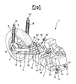
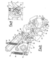
- said group comprises an engine 2, to which the fork 3 is connected, on which the rear wheel 4 is mounted, together with the brake disc 5.
- a sprocket 6 is foreseen, connected through a driving belt 6' to a pulley 7.
- Two rear dampers 8 and 8' and a silencer 9 are also foreseen.
- the frame of the motorcycle is applied onto the engine-suspension group 1.
- Said frame is connected to said rear engine-suspension group 1 and to the fork 3 through two pairs of arms 10, 10' and 11, 11', respectively arranged at the rear and front of said engine 2, coupled together through two transversal cylindrical elements 12, for arms 10, 10', and 13 for arms 11, 11'.
- the pivot of the rear wheel 3 On the axis of the transversal cylindrical element 12 the pivot of the rear wheel 3 is fixed, which rotates on cases with rollers or ball bearings contained in said transversal cylinder 12.
- the rotation of the fork 3 is controlled by the pair of dampers 8 and 8' fixed to the frame and to the fork 3 through silentblock 14, 14' and 15, 15', contained in said pair of dampers 8 and 8'.
- silentblock 15, 15' can be housed directly on the fork 3.
- the rear dampers 8 and 8' foresee a clevis 24 that fixes to the silentblock 15, 15' and then to the fork 3.
- Both of the pairs of arms 10, 10' and 11, 11' are pivoted on the frame through silentblocks 16, 16' and 17, 17' contained in them, or else through means which in any case allow rotation, like for example bearings.
- the silentblocks 16, 16' and 17, 17' allow an elastic connection with respect to the frame.
- the silentblock 20 with axis perpendicular to the pivots of the arms 10, 10' and 11, 11' is fixed to the engine 2 in the middle part of its axis.
- the reaction on the frame is assigned to a side bracket (not shown in the figure) that is gripped by the pair of buffers 22 and by the transversal tension rod 19, which work in opposition.
- the different radial rigidities, axial and torsional, of the silentblocks 20 and 21 and the longitudinal 18 and transversal 19 tension rods allow the engine to be left the freedom of movement necessary to limit the passage of vibrations and allow the movements that influence the driving of the vehicle to be counteracted.
- the rear dampers 8 and 8' are fixed onto the fork 3 at the rear wheel and remain almost vertical during their travel so as to reduce the effects of the forces of the rear suspension on the arms 10, 10' and 11, 11', and on the preload of the pair of buffers 23 of the longitudinal tension rod 18.
- the arms 10, 10' and 11, 11', which support the engine, are orientated so that the weight of the engine 2 does not influence the preload of said pair of buffers 23 of the longitudinal tension rod 18.
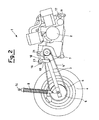
- FIG. 2 it is possible to observe the side view of the engine-suspension group 1, comprising the wheel 4.
- the arms 10 and 11 the longitudinal tension rod 18 and the pair of buffers 23 can be seen.
- the frame, the engine 2 and the arms 10, 10' and 11, 11' form, in the longitudinal plane of the vehicle, a quadrilateral the arms 10, 10' and 11, 11' of which are substantially vertical sides.
- the engine 2 can oscillate in the longitudinal plane but is countered by the longitudinal tension rod 18 and by the torsional rigidity of the silentblocks 16, 16' and 17, 17' and 14, 14' and 15, 15' contained in the arms and in the dampers 8 and 8'.
- the longitudinal tension rod 18 allows small movements of the engine due to vibrations but limits the oscillations deriving from acceleration of the vehicle.
- the reaction on the frame by said longitudinal tension rod 18 is assigned to a bracket (not shown) that is gripped by the pair of buffers 23.
- the rear engine-suspension group keeps the axes of the pinion 7 coming out from the engine 2, of the transversal cylindrical pivot element 12 and of the rear wheel 4 parallel in all of the travel of the dampers 8, 8'.
- the aforementioned parallelism of the axes improves the work of the end transmission from the driving pinion 7 to the rear wheel 4, which can be realised with a toothed belt 6 or even with a chain with rollers.
- the fundamental advantage of the present invention is that of reducing the passage of vibrations from the engine to the vehicle.
- the engine and the frame do not have rigid fitting points, but each connection point has an articulation.
- the connections to the frame of the rear engine-suspension group are not carried out directly through buffers or silentblock, but each attachment is carried out through arms or connecting rods.
Landscapes
- Engineering & Computer Science (AREA)
- Mechanical Engineering (AREA)
- Arrangement Or Mounting Of Propulsion Units For Vehicles (AREA)
- Vehicle Body Suspensions (AREA)
- Axle Suspensions And Sidecars For Cycles (AREA)
- Body Structure For Vehicles (AREA)
Claims (15)
- Verbindungssystem zwischen Rahmen und hinterer Motoraufhängungsgruppe eines Motorfahrzeugs, wobei das genannte Motorfahrzeug einen Rahmen, eine Gabel (3), welche an einem Ende mit der genannten hinteren Motoraufhängungsgruppe (1) und am anderen Ende mit wenigsten einem Rad (4) verbunden ist, umfasst, und wobei das genannte System starre Verbindungsmittel (10, 10' und 11, 11') zwischen dem genannten Rahmen und der genannten hinteren Motoraufhängungsgruppe (1) umfasst, wobei die starren Verbindungsmittel (10, 10' und 11, 11') an der Vorderseite und der Hinterseite des Motors (2) angeordnet sind und mit dem genannten Rahmen mittels erster Verbindungselemente (16, 16' und 17, 17') und mit der genannten hinteren Motoraufhängungsgruppe (1) mittels zweiter Verbindungselemente verbunden sind, dadurch gekennzeichnet, dass weiters wenigstens ein querlaufendes Kupplungsstück (19) und/oder wenigstens ein längslaufendes Kupplungsstück (18) zwischen dem genannten Rahmen und dem genannten Motor (2) vorgesehen sind, wobei jedes des genannten wenigstens einen querlaufenden Kupplungsstückes (19) und des genannten wenigstens einen längslaufenden Kupplungsstückes (18) eine Zugstange aufweist.
- System nach Anspruch 1, dadurch gekennzeichnet, dass die genannte Zugstange des genannten wenigstens einen querlaufenden Kupplungsstückes (19) über ein Paar von Dämpfern (22) mit dem genannten Rahmen verbunden ist.
- System nach Anspruch 1 und 2, dadurch gekennzeichnet, dass die genannte Zugstange des genannten wenigstens einen querlaufenden Kupplungsstückes (19) mit einem Gummilager (20), der an dem genannten Motor (2) angebracht ist, verbunden ist.
- System nach Anspruch 1, dadurch gekennzeichnet, dass die genannte Zugstange des genannten wenigstens einen längslaufenden Kupplungsstückes (18) über ein Paar von Dämpfern (23) mit dem genannten Rahmen verbunden ist.
- System nach Anspruch 1 und 4, dadurch gekennzeichnet, dass die genannte Zugstange des genannten wenigstens einen längslaufenden Kupplungsstückes (18) mit einem Gummilager (21) an den genannten Motor (2) gekoppelt ist.
- System nach Anspruch 1, dadurch gekennzeichnet, dass die genannten Verbindungselemente (10, 10' und 11, 11') Ausleger umfassen.
- System nach Anspruch 6, dadurch gekennzeichnet, dass die genannten Verbindungselemente (10, 10' und 11, 11') zwei Paare von Auslegern umfassen.
- System nach Anspruch 7, dadurch gekennzeichnet, dass jedes der genannten Paare von Auslegern durch ein querstehendes, zylindrisches Element (12, 13) verbunden sind.
- System nach Anspruch 1, dadurch gekennzeichnet, dass die genannten ersten Verbindungselemente (16, 16' und 17, 17') und die genannten zweiten Verbindungsmittel Elemente umfassen, die eine Rotation zulassen.
- System nach Anspruch 9, dadurch gekennzeichnet, dass die Elemente, die eine Rotation zulassen, Gummilager oder Lager umfassen.
- System nach Anspruch 1, dadurch gekennzeichnet, dass die genannte Gabel (3) mit Dämpfungsmitteln (8, 8') mit dem Rahmen verbunden ist.
- System nach Anspruch 11, dadurch gekennzeichnet, dass die genannte Gabel (3) Verbindungs-Gummilager (14, 14' und 15, 15') an den Enden der genannten Dämpfungsmittel (8, 8') umfasst, die mit einem Bohrloch versehen sind.
- System nach Anspruch 11, dadurch gekennzeichnet, dass die genannte Gabel (3) mit den Verbindungs-Gummilager (14, 14' und 15, 15'), die an den Enden der genannten Dämpfungsmittel (8, 8') angebracht sind, verbunden ist.
- System nach Anspruch 11, dadurch gekennzeichnet, dass die genannten Dämpfungsmittel (8, 8') zwei Dämpfer aufweisen.
- System nach Anspruch 12, dadurch gekennzeichnet, dass die genannten Dämpfungsmittel (8, 8') während ihrer Bewegung im wesentlichen lotrecht zum Boden bleiben.
Applications Claiming Priority (2)
| Application Number | Priority Date | Filing Date | Title |
|---|---|---|---|
| IT001053A ITMI20031053A1 (it) | 2003-05-26 | 2003-05-26 | Sistema di accoppiamento tra telaio e gruppo motore-sospensione posteriore di un motoveicolo |
| ITMI20031053 | 2003-05-26 |
Publications (3)
| Publication Number | Publication Date |
|---|---|
| EP1481886A2 EP1481886A2 (de) | 2004-12-01 |
| EP1481886A3 EP1481886A3 (de) | 2006-04-12 |
| EP1481886B1 true EP1481886B1 (de) | 2008-09-10 |
Family
ID=30131083
Family Applications (1)
| Application Number | Title | Priority Date | Filing Date |
|---|---|---|---|
| EP04076525A Expired - Lifetime EP1481886B1 (de) | 2003-05-26 | 2004-05-24 | Kupplungssystem zwischen Rahmen und Hinteraufhängung/motor Gruppe eines Kraftfahrzeugs |
Country Status (7)
| Country | Link |
|---|---|
| EP (1) | EP1481886B1 (de) |
| CN (1) | CN100335306C (de) |
| AT (1) | ATE407867T1 (de) |
| DE (1) | DE602004016414D1 (de) |
| ES (1) | ES2312916T3 (de) |
| IT (1) | ITMI20031053A1 (de) |
| TW (1) | TWI327979B (de) |
Families Citing this family (2)
| Publication number | Priority date | Publication date | Assignee | Title |
|---|---|---|---|---|
| JP5728272B2 (ja) * | 2011-03-31 | 2015-06-03 | 本田技研工業株式会社 | 電動車両 |
| CN106542037B (zh) * | 2015-09-22 | 2019-03-29 | 光阳工业股份有限公司 | 摩托车后叉结构 |
Family Cites Families (5)
| Publication number | Priority date | Publication date | Assignee | Title |
|---|---|---|---|---|
| US4373602A (en) * | 1980-03-06 | 1983-02-15 | Honda Giken Kogyo Kabushiki Kaisha | Power unit suspension system for motorcycles |
| JP3485996B2 (ja) * | 1995-04-11 | 2004-01-13 | 本田技研工業株式会社 | スイングユニット式車両におけるスイングアーム構造 |
| TW446664B (en) * | 1999-05-25 | 2001-07-21 | Honda Motor Co Ltd | Scooter type motorcycle |
| JP4205297B2 (ja) * | 2000-09-08 | 2009-01-07 | 本田技研工業株式会社 | 自動二輪車のエンジン取付構造 |
| JP3801901B2 (ja) * | 2001-10-23 | 2006-07-26 | 本田技研工業株式会社 | 自動二輪車のエンジン取付構造 |
-
2003
- 2003-05-26 IT IT001053A patent/ITMI20031053A1/it unknown
-
2004
- 2004-05-24 TW TW093114624A patent/TWI327979B/zh active
- 2004-05-24 DE DE602004016414T patent/DE602004016414D1/de not_active Expired - Lifetime
- 2004-05-24 EP EP04076525A patent/EP1481886B1/de not_active Expired - Lifetime
- 2004-05-24 AT AT04076525T patent/ATE407867T1/de not_active IP Right Cessation
- 2004-05-24 ES ES04076525T patent/ES2312916T3/es not_active Expired - Lifetime
- 2004-05-26 CN CNB2004100475914A patent/CN100335306C/zh not_active Expired - Lifetime
Also Published As
| Publication number | Publication date |
|---|---|
| ATE407867T1 (de) | 2008-09-15 |
| EP1481886A2 (de) | 2004-12-01 |
| CN100335306C (zh) | 2007-09-05 |
| TW200505726A (en) | 2005-02-16 |
| DE602004016414D1 (de) | 2008-10-23 |
| EP1481886A3 (de) | 2006-04-12 |
| ES2312916T3 (es) | 2009-03-01 |
| ITMI20031053A1 (it) | 2004-11-27 |
| ITMI20031053A0 (it) | 2003-05-26 |
| TWI327979B (en) | 2010-08-01 |
| CN1572562A (zh) | 2005-02-02 |
Similar Documents
| Publication | Publication Date | Title |
|---|---|---|
| JP4837531B2 (ja) | 後輪懸架構造 | |
| JP4733538B2 (ja) | 自動二輪車 | |
| JP4071577B2 (ja) | 自動二輪車等車両におけるリンク式フロントサスペンション装置 | |
| JP2007230537A (ja) | フレーム構造 | |
| MXPA05009753A (es) | Estructura de armazon. | |
| AU594707B2 (en) | Saddle type vehicle running on uneven ground | |
| JP4287136B2 (ja) | 車両のサスペンション配置構造 | |
| US7641015B2 (en) | Motorcycle | |
| JP2006232061A (ja) | 鞍乗り型不整地走行車両 | |
| US4436174A (en) | Vehicular power unit supporting device | |
| JP4558432B2 (ja) | スイングアーム部構造 | |
| EP1481886B1 (de) | Kupplungssystem zwischen Rahmen und Hinteraufhängung/motor Gruppe eines Kraftfahrzeugs | |
| US20100013180A1 (en) | Three-wheeled vehicle with rear axle control link | |
| US10065700B2 (en) | Arrangement for the vibration decoupling of a motor for motorized two-wheelers, having an engine-mount swing arm | |
| US4655310A (en) | Automotive vehicle | |
| JP4575256B2 (ja) | 四輪車両 | |
| CN100532186C (zh) | 摩托车 | |
| JPH05221370A (ja) | スクータのパワーユニット懸架装置 | |
| EP1495957B1 (de) | Kopplung zwischen Rahmen und Motor eines Motorfahrzeugs | |
| JPS647918B2 (de) | ||
| JPH0547033Y2 (de) | ||
| JPH02162186A (ja) | 自動二輪車のパワーユニット懸架装置 | |
| JP2550342B2 (ja) | 車両用パワ−プラント体の支持構造 | |
| EP1693293B1 (de) | Kraftübertragungssystem | |
| JPH11342886A (ja) | スクーターのパワーユニット懸架装置 |
Legal Events
| Date | Code | Title | Description |
|---|---|---|---|
| PUAI | Public reference made under article 153(3) epc to a published international application that has entered the european phase |
Free format text: ORIGINAL CODE: 0009012 |
|
| AK | Designated contracting states |
Kind code of ref document: A2 Designated state(s): AT BE BG CH CY CZ DE DK EE ES FI FR GB GR HU IE IT LI LU MC NL PL PT RO SE SI SK TR |
|
| AX | Request for extension of the european patent |
Extension state: AL HR LT LV MK |
|
| PUAL | Search report despatched |
Free format text: ORIGINAL CODE: 0009013 |
|
| AK | Designated contracting states |
Kind code of ref document: A3 Designated state(s): AT BE BG CH CY CZ DE DK EE ES FI FR GB GR HU IE IT LI LU MC NL PL PT RO SE SI SK TR |
|
| AX | Request for extension of the european patent |
Extension state: AL HR LT LV MK |
|
| 17P | Request for examination filed |
Effective date: 20061003 |
|
| AKX | Designation fees paid |
Designated state(s): AT BE BG CH CY CZ DE DK EE ES FI FR GB GR HU IE IT LI LU MC NL PL PT RO SE SI SK TR |
|
| 17Q | First examination report despatched |
Effective date: 20061124 |
|
| GRAP | Despatch of communication of intention to grant a patent |
Free format text: ORIGINAL CODE: EPIDOSNIGR1 |
|
| GRAS | Grant fee paid |
Free format text: ORIGINAL CODE: EPIDOSNIGR3 |
|
| GRAA | (expected) grant |
Free format text: ORIGINAL CODE: 0009210 |
|
| AK | Designated contracting states |
Kind code of ref document: B1 Designated state(s): AT BE BG CH CY CZ DE DK EE ES FI FR GB GR HU IE IT LI LU MC NL PL PT RO SE SI SK TR |
|
| REG | Reference to a national code |
Ref country code: GB Ref legal event code: FG4D |
|
| REG | Reference to a national code |
Ref country code: CH Ref legal event code: EP |
|
| REG | Reference to a national code |
Ref country code: IE Ref legal event code: FG4D |
|
| REF | Corresponds to: |
Ref document number: 602004016414 Country of ref document: DE Date of ref document: 20081023 Kind code of ref document: P |
|
| REG | Reference to a national code |
Ref country code: GR Ref legal event code: EP Ref document number: 20080403288 Country of ref document: GR |
|
| PG25 | Lapsed in a contracting state [announced via postgrant information from national office to epo] |
Ref country code: AT Free format text: LAPSE BECAUSE OF FAILURE TO SUBMIT A TRANSLATION OF THE DESCRIPTION OR TO PAY THE FEE WITHIN THE PRESCRIBED TIME-LIMIT Effective date: 20080910 Ref country code: FI Free format text: LAPSE BECAUSE OF FAILURE TO SUBMIT A TRANSLATION OF THE DESCRIPTION OR TO PAY THE FEE WITHIN THE PRESCRIBED TIME-LIMIT Effective date: 20080910 Ref country code: SI Free format text: LAPSE BECAUSE OF FAILURE TO SUBMIT A TRANSLATION OF THE DESCRIPTION OR TO PAY THE FEE WITHIN THE PRESCRIBED TIME-LIMIT Effective date: 20080910 |
|
| REG | Reference to a national code |
Ref country code: ES Ref legal event code: FG2A Ref document number: 2312916 Country of ref document: ES Kind code of ref document: T3 |
|
| NLV1 | Nl: lapsed or annulled due to failure to fulfill the requirements of art. 29p and 29m of the patents act | ||
| PG25 | Lapsed in a contracting state [announced via postgrant information from national office to epo] |
Ref country code: BE Free format text: LAPSE BECAUSE OF FAILURE TO SUBMIT A TRANSLATION OF THE DESCRIPTION OR TO PAY THE FEE WITHIN THE PRESCRIBED TIME-LIMIT Effective date: 20080910 |
|
| PG25 | Lapsed in a contracting state [announced via postgrant information from national office to epo] |
Ref country code: BG Free format text: LAPSE BECAUSE OF FAILURE TO SUBMIT A TRANSLATION OF THE DESCRIPTION OR TO PAY THE FEE WITHIN THE PRESCRIBED TIME-LIMIT Effective date: 20081210 |
|
| PG25 | Lapsed in a contracting state [announced via postgrant information from national office to epo] |
Ref country code: SK Free format text: LAPSE BECAUSE OF FAILURE TO SUBMIT A TRANSLATION OF THE DESCRIPTION OR TO PAY THE FEE WITHIN THE PRESCRIBED TIME-LIMIT Effective date: 20080910 Ref country code: CZ Free format text: LAPSE BECAUSE OF FAILURE TO SUBMIT A TRANSLATION OF THE DESCRIPTION OR TO PAY THE FEE WITHIN THE PRESCRIBED TIME-LIMIT Effective date: 20080910 Ref country code: RO Free format text: LAPSE BECAUSE OF FAILURE TO SUBMIT A TRANSLATION OF THE DESCRIPTION OR TO PAY THE FEE WITHIN THE PRESCRIBED TIME-LIMIT Effective date: 20080910 Ref country code: PT Free format text: LAPSE BECAUSE OF FAILURE TO SUBMIT A TRANSLATION OF THE DESCRIPTION OR TO PAY THE FEE WITHIN THE PRESCRIBED TIME-LIMIT Effective date: 20090210 Ref country code: NL Free format text: LAPSE BECAUSE OF FAILURE TO SUBMIT A TRANSLATION OF THE DESCRIPTION OR TO PAY THE FEE WITHIN THE PRESCRIBED TIME-LIMIT Effective date: 20080910 |
|
| PLBE | No opposition filed within time limit |
Free format text: ORIGINAL CODE: 0009261 |
|
| STAA | Information on the status of an ep patent application or granted ep patent |
Free format text: STATUS: NO OPPOSITION FILED WITHIN TIME LIMIT |
|
| PG25 | Lapsed in a contracting state [announced via postgrant information from national office to epo] |
Ref country code: DK Free format text: LAPSE BECAUSE OF FAILURE TO SUBMIT A TRANSLATION OF THE DESCRIPTION OR TO PAY THE FEE WITHIN THE PRESCRIBED TIME-LIMIT Effective date: 20080910 Ref country code: EE Free format text: LAPSE BECAUSE OF FAILURE TO SUBMIT A TRANSLATION OF THE DESCRIPTION OR TO PAY THE FEE WITHIN THE PRESCRIBED TIME-LIMIT Effective date: 20080910 |
|
| 26N | No opposition filed |
Effective date: 20090611 |
|
| PG25 | Lapsed in a contracting state [announced via postgrant information from national office to epo] |
Ref country code: MC Free format text: LAPSE BECAUSE OF NON-PAYMENT OF DUE FEES Effective date: 20090531 |
|
| REG | Reference to a national code |
Ref country code: CH Ref legal event code: PL |
|
| PG25 | Lapsed in a contracting state [announced via postgrant information from national office to epo] |
Ref country code: SE Free format text: LAPSE BECAUSE OF FAILURE TO SUBMIT A TRANSLATION OF THE DESCRIPTION OR TO PAY THE FEE WITHIN THE PRESCRIBED TIME-LIMIT Effective date: 20081210 Ref country code: LI Free format text: LAPSE BECAUSE OF NON-PAYMENT OF DUE FEES Effective date: 20090531 Ref country code: CH Free format text: LAPSE BECAUSE OF NON-PAYMENT OF DUE FEES Effective date: 20090531 |
|
| REG | Reference to a national code |
Ref country code: IE Ref legal event code: MM4A |
|
| PG25 | Lapsed in a contracting state [announced via postgrant information from national office to epo] |
Ref country code: IE Free format text: LAPSE BECAUSE OF NON-PAYMENT OF DUE FEES Effective date: 20090524 |
|
| PG25 | Lapsed in a contracting state [announced via postgrant information from national office to epo] |
Ref country code: PL Free format text: LAPSE BECAUSE OF FAILURE TO SUBMIT A TRANSLATION OF THE DESCRIPTION OR TO PAY THE FEE WITHIN THE PRESCRIBED TIME-LIMIT Effective date: 20080910 |
|
| PG25 | Lapsed in a contracting state [announced via postgrant information from national office to epo] |
Ref country code: GR Free format text: LAPSE BECAUSE OF NON-PAYMENT OF DUE FEES Effective date: 20091202 |
|
| PG25 | Lapsed in a contracting state [announced via postgrant information from national office to epo] |
Ref country code: LU Free format text: LAPSE BECAUSE OF NON-PAYMENT OF DUE FEES Effective date: 20090524 |
|
| PG25 | Lapsed in a contracting state [announced via postgrant information from national office to epo] |
Ref country code: HU Free format text: LAPSE BECAUSE OF FAILURE TO SUBMIT A TRANSLATION OF THE DESCRIPTION OR TO PAY THE FEE WITHIN THE PRESCRIBED TIME-LIMIT Effective date: 20090311 |
|
| PG25 | Lapsed in a contracting state [announced via postgrant information from national office to epo] |
Ref country code: TR Free format text: LAPSE BECAUSE OF FAILURE TO SUBMIT A TRANSLATION OF THE DESCRIPTION OR TO PAY THE FEE WITHIN THE PRESCRIBED TIME-LIMIT Effective date: 20080910 |
|
| PG25 | Lapsed in a contracting state [announced via postgrant information from national office to epo] |
Ref country code: CY Free format text: LAPSE BECAUSE OF FAILURE TO SUBMIT A TRANSLATION OF THE DESCRIPTION OR TO PAY THE FEE WITHIN THE PRESCRIBED TIME-LIMIT Effective date: 20080910 |
|
| REG | Reference to a national code |
Ref country code: FR Ref legal event code: PLFP Year of fee payment: 13 |
|
| REG | Reference to a national code |
Ref country code: FR Ref legal event code: PLFP Year of fee payment: 14 |
|
| REG | Reference to a national code |
Ref country code: FR Ref legal event code: PLFP Year of fee payment: 15 |
|
| PGFP | Annual fee paid to national office [announced via postgrant information from national office to epo] |
Ref country code: GB Payment date: 20220519 Year of fee payment: 19 Ref country code: FR Payment date: 20220530 Year of fee payment: 19 Ref country code: ES Payment date: 20220601 Year of fee payment: 19 Ref country code: DE Payment date: 20220519 Year of fee payment: 19 |
|
| P01 | Opt-out of the competence of the unified patent court (upc) registered |
Effective date: 20230529 |
|
| PGFP | Annual fee paid to national office [announced via postgrant information from national office to epo] |
Ref country code: IT Payment date: 20230405 Year of fee payment: 20 |
|
| REG | Reference to a national code |
Ref country code: DE Ref legal event code: R119 Ref document number: 602004016414 Country of ref document: DE |
|
| GBPC | Gb: european patent ceased through non-payment of renewal fee |
Effective date: 20230524 |
|
| PG25 | Lapsed in a contracting state [announced via postgrant information from national office to epo] |
Ref country code: DE Free format text: LAPSE BECAUSE OF NON-PAYMENT OF DUE FEES Effective date: 20231201 Ref country code: GB Free format text: LAPSE BECAUSE OF NON-PAYMENT OF DUE FEES Effective date: 20230524 |