EP1481886B1 - Coupling system between frame and rear engine-suspension group of a motor vehicle - Google Patents
Coupling system between frame and rear engine-suspension group of a motor vehicle Download PDFInfo
- Publication number
- EP1481886B1 EP1481886B1 EP04076525A EP04076525A EP1481886B1 EP 1481886 B1 EP1481886 B1 EP 1481886B1 EP 04076525 A EP04076525 A EP 04076525A EP 04076525 A EP04076525 A EP 04076525A EP 1481886 B1 EP1481886 B1 EP 1481886B1
- Authority
- EP
- European Patent Office
- Prior art keywords
- frame
- engine
- coupling
- fork
- suspension group
- Prior art date
- Legal status (The legal status is an assumption and is not a legal conclusion. Google has not performed a legal analysis and makes no representation as to the accuracy of the status listed.)
- Active
Links
- 239000000725 suspension Substances 0.000 title claims abstract description 19
- 230000008878 coupling Effects 0.000 title claims description 18
- 238000010168 coupling process Methods 0.000 title claims description 18
- 238000005859 coupling reaction Methods 0.000 title claims description 18
- 239000000872 buffer Substances 0.000 claims description 10
- 238000013016 damping Methods 0.000 claims description 6
- 230000033001 locomotion Effects 0.000 description 5
- 238000006243 chemical reaction Methods 0.000 description 3
- 230000001133 acceleration Effects 0.000 description 2
- 230000000694 effects Effects 0.000 description 2
- 230000036316 preload Effects 0.000 description 2
- 230000005540 biological transmission Effects 0.000 description 1
- 230000000903 blocking effect Effects 0.000 description 1
- 238000012986 modification Methods 0.000 description 1
- 230000004048 modification Effects 0.000 description 1
- 230000010355 oscillation Effects 0.000 description 1
- 239000003380 propellant Substances 0.000 description 1
- 230000003584 silencer Effects 0.000 description 1
Images
Classifications
-
- B—PERFORMING OPERATIONS; TRANSPORTING
- B62—LAND VEHICLES FOR TRAVELLING OTHERWISE THAN ON RAILS
- B62K—CYCLES; CYCLE FRAMES; CYCLE STEERING DEVICES; RIDER-OPERATED TERMINAL CONTROLS SPECIALLY ADAPTED FOR CYCLES; CYCLE AXLE SUSPENSIONS; CYCLE SIDE-CARS, FORECARS, OR THE LIKE
- B62K25/00—Axle suspensions
- B62K25/04—Axle suspensions for mounting axles resiliently on cycle frame or fork
- B62K25/28—Axle suspensions for mounting axles resiliently on cycle frame or fork with pivoted chain-stay
- B62K25/283—Axle suspensions for mounting axles resiliently on cycle frame or fork with pivoted chain-stay for cycles without a pedal crank, e.g. motorcycles
Definitions
- the present invention concerns a coupling system between frame and rear engine-suspension group of a motor vehicle.
- the invention concerns a system of said type, researched and realised in particular to reduce the passage of vibrations produced, for example, by a spark-ignition engine, and the torsional effects with respect to the axial plane of motion, but which can be used for any system or means equivalent to the one indicated.
- Document EP-A-1 186 526 discloses a coupling system between frame and rear engine-suspension group of a motorcycle according to the preamble of claim 1, wherein a plurality of mutually parallel connection elements between frame and engine are provided.
- Document EP-A-0 737 615 discloses a swing arm structure for supporting an axle of a motorcycle rear wheel, the swing arm being connected to the motorcycle engine through a pair of bolts.
- said group comprises an engine 2, to which the fork 3 is connected, on which the rear wheel 4 is mounted, together with the brake disc 5.
- a sprocket 6 is foreseen, connected through a driving belt 6' to a pulley 7.
- Two rear dampers 8 and 8' and a silencer 9 are also foreseen.
- the frame of the motorcycle is applied onto the engine-suspension group 1.
- Said frame is connected to said rear engine-suspension group 1 and to the fork 3 through two pairs of arms 10, 10' and 11, 11', respectively arranged at the rear and front of said engine 2, coupled together through two transversal cylindrical elements 12, for arms 10, 10', and 13 for arms 11, 11'.
- the pivot of the rear wheel 3 On the axis of the transversal cylindrical element 12 the pivot of the rear wheel 3 is fixed, which rotates on cases with rollers or ball bearings contained in said transversal cylinder 12.
- the rotation of the fork 3 is controlled by the pair of dampers 8 and 8' fixed to the frame and to the fork 3 through silentblock 14, 14' and 15, 15', contained in said pair of dampers 8 and 8'.
- silentblock 15, 15' can be housed directly on the fork 3.
- the rear dampers 8 and 8' foresee a clevis 24 that fixes to the silentblock 15, 15' and then to the fork 3.
- Both of the pairs of arms 10, 10' and 11, 11' are pivoted on the frame through silentblocks 16, 16' and 17, 17' contained in them, or else through means which in any case allow rotation, like for example bearings.
- the silentblocks 16, 16' and 17, 17' allow an elastic connection with respect to the frame.
- the silentblock 20 with axis perpendicular to the pivots of the arms 10, 10' and 11, 11' is fixed to the engine 2 in the middle part of its axis.
- the reaction on the frame is assigned to a side bracket (not shown in the figure) that is gripped by the pair of buffers 22 and by the transversal tension rod 19, which work in opposition.
- the different radial rigidities, axial and torsional, of the silentblocks 20 and 21 and the longitudinal 18 and transversal 19 tension rods allow the engine to be left the freedom of movement necessary to limit the passage of vibrations and allow the movements that influence the driving of the vehicle to be counteracted.
- the rear dampers 8 and 8' are fixed onto the fork 3 at the rear wheel and remain almost vertical during their travel so as to reduce the effects of the forces of the rear suspension on the arms 10, 10' and 11, 11', and on the preload of the pair of buffers 23 of the longitudinal tension rod 18.
- the arms 10, 10' and 11, 11', which support the engine, are orientated so that the weight of the engine 2 does not influence the preload of said pair of buffers 23 of the longitudinal tension rod 18.
- FIG. 2 it is possible to observe the side view of the engine-suspension group 1, comprising the wheel 4.
- the arms 10 and 11 the longitudinal tension rod 18 and the pair of buffers 23 can be seen.
- the frame, the engine 2 and the arms 10, 10' and 11, 11' form, in the longitudinal plane of the vehicle, a quadrilateral the arms 10, 10' and 11, 11' of which are substantially vertical sides.
- the engine 2 can oscillate in the longitudinal plane but is countered by the longitudinal tension rod 18 and by the torsional rigidity of the silentblocks 16, 16' and 17, 17' and 14, 14' and 15, 15' contained in the arms and in the dampers 8 and 8'.
- the longitudinal tension rod 18 allows small movements of the engine due to vibrations but limits the oscillations deriving from acceleration of the vehicle.
- the reaction on the frame by said longitudinal tension rod 18 is assigned to a bracket (not shown) that is gripped by the pair of buffers 23.
- the rear engine-suspension group keeps the axes of the pinion 7 coming out from the engine 2, of the transversal cylindrical pivot element 12 and of the rear wheel 4 parallel in all of the travel of the dampers 8, 8'.
- the aforementioned parallelism of the axes improves the work of the end transmission from the driving pinion 7 to the rear wheel 4, which can be realised with a toothed belt 6 or even with a chain with rollers.
- the fundamental advantage of the present invention is that of reducing the passage of vibrations from the engine to the vehicle.
- the engine and the frame do not have rigid fitting points, but each connection point has an articulation.
- the connections to the frame of the rear engine-suspension group are not carried out directly through buffers or silentblock, but each attachment is carried out through arms or connecting rods.
Landscapes
- Engineering & Computer Science (AREA)
- Mechanical Engineering (AREA)
- Arrangement Or Mounting Of Propulsion Units For Vehicles (AREA)
- Vehicle Body Suspensions (AREA)
- Axle Suspensions And Sidecars For Cycles (AREA)
- Body Structure For Vehicles (AREA)
Abstract
Description
- The present invention concerns a coupling system between frame and rear engine-suspension group of a motor vehicle.
- In greater detail, the invention concerns a system of said type, researched and realised in particular to reduce the passage of vibrations produced, for example, by a spark-ignition engine, and the torsional effects with respect to the axial plane of motion, but which can be used for any system or means equivalent to the one indicated.
- Hereafter, the description shall focus upon application to a motorcycle, but it is clear how it does not have to be considered limited to this specific use.
- It is well known that currently the performance of propellants of motorcycles is increasing very quickly. This involves the need to give, at the design stage, particular attention to the equipping of such means with sophisticated systems and devices, suitable for the safety of the driver and the comfort of the ride itself. Indeed, the acceleration capability and the road-holding capability when cornering and on demanding road sections involve ever greater stresses between the frame and the engine group and on the frame itself.
- Currently, devices are known that allow the damping of vibrations, such as tension rods, generally associated with buffers, inserted in many contact points, which allow a reaction to the stresses between the various parts that make up the motorcycle, which may be stressed and/or stress each other, to be applied. Amongst the aforementioned parts most involved in this type of problems, we must consider in particular the rear fork, with which the rear driving-wheel is coupled, the motorcycle frame and the engine group.
- Moreover, in the points of contact, devices are also foreseen that allow an elastic coupling, also known as "silentblock", which allow the vibrations to be damped effectively.
- However, currently the systems listed above, following the increase in propulsion power, do not allow an effective blocking of the passage of vibrations from the engine to the frame.
- It is also known how the basic parts of a motorcycle, that is the engine group, the rear fork together with the driving-wheel, and the frame thereof, are stresses independently and that it would therefore be suitable, as well as to attenuate the propagation of vibrations from the engine to the frame, also to make the overall structure equipped with suitable rigidity, which allows the torsional stresses to which the various parts of the motorcycle are subjected to be reduced.
- Document
EP-A-1 186 526 discloses a coupling system between frame and rear engine-suspension group of a motorcycle according to the preamble of claim 1, wherein a plurality of mutually parallel connection elements between frame and engine are provided. - Document
EP-A-0 737 615 discloses a swing arm structure for supporting an axle of a motorcycle rear wheel, the swing arm being connected to the motorcycle engine through a pair of bolts. - In light of the above, it is clear that there is a need to be able to have a system like the one according to the present invention that allows a frame - fork/wheel - engine group connection to be created that minimises the propagation of vibrations between the engine group and the frame.
- Therefore, the specific object of the present invention is achieved with a coupling system between frame and rear engine-suspension group of a motor vehicle as described in claim 1.
- Further characteristics of the invention are illustrated in the subsequent claims.
- The present invention shall now be described for indicating but not limiting purposes, according to its preferred embodiments, with particular reference to the figures of the attached drawings, in which:
-
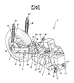
Figure 1 shows a first perspective view of the engine-suspension-rear wheel group of a motorcycle comprising the system according to the present invention; -
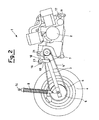
Figure 2 is a side view of the engine-suspension-rear wheel group of 1; -
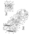
Figure 3 shows a perspective view of the rear engine-suspension group of a motorcycle comprising the system according to the present invention; and -
Figure 4 shows a perspective view of a particular alternative attachment between damper and fork. - To better understand the present invention, hereafter we describe the operating modes of the preferred embodiment, with analogous modes being valid for other possible embodiments.
- With reference to the attached figures it is possible to observe an engine-suspension group 1 of a motorcycle with (
figures 1 and3 ) and without (figure 3 ) a wheel 4, comprising the solution of the present invention. In particular, said group comprises anengine 2, to which thefork 3 is connected, on which the rear wheel 4 is mounted, together with thebrake disc 5. On the axis of the rear wheel 4 asprocket 6 is foreseen, connected through a driving belt 6' to apulley 7. Tworear dampers 8 and 8' and asilencer 9 are also foreseen. - The frame of the motorcycle, not shown in the figures, is applied onto the engine-suspension group 1. Said frame is connected to said rear engine-suspension group 1 and to the
fork 3 through two pairs ofarms engine 2, coupled together through two transversalcylindrical elements 12, forarms arms 11, 11'. - On the axis of the transversal
cylindrical element 12 the pivot of therear wheel 3 is fixed, which rotates on cases with rollers or ball bearings contained in saidtransversal cylinder 12. The rotation of thefork 3 is controlled by the pair ofdampers 8 and 8' fixed to the frame and to thefork 3 throughsilentblock dampers 8 and 8'. - Alternatively,
silentblock 15, 15', as shown infigure 4 , can be housed directly on thefork 3. In this case therear dampers 8 and 8' foresee aclevis 24 that fixes to thesilentblock 15, 15' and then to thefork 3. - Both of the pairs of
arms silentblocks silentblocks - Further connections between the frame and the engine-suspension group 1 are foreseen, which comprise a
longitudinal tension rod 18 and atransversal tension rod 19. The movements of the rear engine-suspension group 1, in the vertical and horizontal transversal planes, are limited by the presence of saidtension rods silentblocks arms dampers 8 and 8'. Said tension rods are also connected to the engine throughsilentblocks buffers silentblock 20 with axis perpendicular to the pivots of thearms engine 2 in the middle part of its axis. The reaction on the frame is assigned to a side bracket (not shown in the figure) that is gripped by the pair ofbuffers 22 and by thetransversal tension rod 19, which work in opposition. - The different radial rigidities, axial and torsional, of the
silentblocks rear dampers 8 and 8' are fixed onto thefork 3 at the rear wheel and remain almost vertical during their travel so as to reduce the effects of the forces of the rear suspension on thearms buffers 23 of thelongitudinal tension rod 18. Thearms engine 2 does not influence the preload of said pair ofbuffers 23 of thelongitudinal tension rod 18. - Considering, in particular,
figure 2 , it is possible to observe the side view of the engine-suspension group 1, comprising the wheel 4. In particular, thearms longitudinal tension rod 18 and the pair ofbuffers 23 can be seen. - Through this figure it can be seen that the frame, the
engine 2 and thearms arms engine 2 can oscillate in the longitudinal plane but is countered by thelongitudinal tension rod 18 and by the torsional rigidity of thesilentblocks dampers 8 and 8'. Thelongitudinal tension rod 18 allows small movements of the engine due to vibrations but limits the oscillations deriving from acceleration of the vehicle. The reaction on the frame by saidlongitudinal tension rod 18 is assigned to a bracket (not shown) that is gripped by the pair ofbuffers 23. - Thanks to the absence of elastic elements in the connection between the fork and the engine, the rear engine-suspension group keeps the axes of the
pinion 7 coming out from theengine 2, of the transversalcylindrical pivot element 12 and of the rear wheel 4 parallel in all of the travel of thedampers 8, 8'. The aforementioned parallelism of the axes improves the work of the end transmission from the drivingpinion 7 to the rear wheel 4, which can be realised with atoothed belt 6 or even with a chain with rollers. - Based upon the previous description, it can be observed that the fundamental advantage of the present invention is that of reducing the passage of vibrations from the engine to the vehicle. In particular, the engine and the frame do not have rigid fitting points, but each connection point has an articulation. The connections to the frame of the rear engine-suspension group are not carried out directly through buffers or silentblock, but each attachment is carried out through arms or connecting rods.
- The present invention has been described for illustrative but not limiting purposes, according to its preferred embodiments, but it should be understood that variations and/or modifications can be made by men skilled in the art without for this reason departing from the relative scope of protection, as defined by the attached claims.
Claims (15)
- Coupling system between frame and rear engine-suspension group of a motor vehicle, said motor vehicle comprising a frame, a fork (3) coupled at one end with said rear engine-suspension group (1) and at the other end with at least one wheel (4), said system comprising rigid connection elements (10, 10' and 11, 11') between said frame and said rear engine-suspension group (1), said rigid connection elements (10, 10' and 11, 11') being arranged at the front and rear of the engine (2) and being coupled with said frame by means of first coupling means (16, 16' and 17, 17') and with said rear engine-suspension group (1) by means of second coupling means, characterised in that at least one transversal coupling (19) and/or at least one longitudinal coupling (18) are furthermore provided between said frame and said engine (2), each of said at least one transversal coupling (19) and of said at least one longitudinal coupling (18) comprising a tension rod.
- System according to claim 1, characterised in that said tension rod of said at least one transversal coupling (19) is connected to said frame through a pair of buffers (22).
- System according to claims 1 and 2, characterised in that said tension rod of said at least one transversal coupling (19) is coupled with a silentblock (20) arranged on said engine (2).
- System according to claim 1, characterised in that said tension rod of said at least one longitudinal coupling (18) is connected to said frame through a pair of buffers (23).
- System according to claims 1 and 4, characterised in that said tension rod of said at least one longitudinal coupling (18) is coupled with a silentblock (21) on said engine (2).
- System according to claim 1, characterised in that said connection elements (10, 10' and 11, 11') comprise arms.
- System according to claim 6, characterised in that said connection elements (10, 10' and 11, 11') comprise two pairs of arms.
- System according to claim 7, characterised in that each of said pairs of arms are connected through a transversal cylindrical element (12, 13).
- System according to claim 1, characterised in that said first coupling means (16, 16' and 17, 17') and said second coupling means comprise elements that allow rotation.
- System according to claim 9, characterised in that said elements that allow rotation comprise silentblocks or bearings.
- System according to claim 1, characterised in that said fork (3) is connected to the frame by means of damping means (8, 8').
- System according to claim 11, characterised in that said fork (3) incorporates connection silentblocks (14, 14' and 15, 15') at ends of said damping means (8, 8') equipped with clevis.
- System according to claim 11, characterised in that said fork (3) is connected to connection silentblocks 14, 14' and 15, 15') incorporated in ends of said damping means (8, 8').
- System according to claim 11, characterised in that said damping means (8, 8') comprise two dampers.
- System according to claim 12, characterised in that said damping means (8, 8') remain substantially vertical relative to the ground during their travel.
Applications Claiming Priority (2)
| Application Number | Priority Date | Filing Date | Title |
|---|---|---|---|
| IT001053A ITMI20031053A1 (en) | 2003-05-26 | 2003-05-26 | COUPLING SYSTEM BETWEEN FRAME AND ENGINE ASSEMBLY - REAR SUSPENSION OF A MOTOR VEHICLE |
| ITMI20031053 | 2003-05-26 |
Publications (3)
| Publication Number | Publication Date |
|---|---|
| EP1481886A2 EP1481886A2 (en) | 2004-12-01 |
| EP1481886A3 EP1481886A3 (en) | 2006-04-12 |
| EP1481886B1 true EP1481886B1 (en) | 2008-09-10 |
Family
ID=30131083
Family Applications (1)
| Application Number | Title | Priority Date | Filing Date |
|---|---|---|---|
| EP04076525A Active EP1481886B1 (en) | 2003-05-26 | 2004-05-24 | Coupling system between frame and rear engine-suspension group of a motor vehicle |
Country Status (7)
| Country | Link |
|---|---|
| EP (1) | EP1481886B1 (en) |
| CN (1) | CN100335306C (en) |
| AT (1) | ATE407867T1 (en) |
| DE (1) | DE602004016414D1 (en) |
| ES (1) | ES2312916T3 (en) |
| IT (1) | ITMI20031053A1 (en) |
| TW (1) | TWI327979B (en) |
Families Citing this family (2)
| Publication number | Priority date | Publication date | Assignee | Title |
|---|---|---|---|---|
| JP5728272B2 (en) * | 2011-03-31 | 2015-06-03 | 本田技研工業株式会社 | Electric vehicle |
| CN106542037B (en) * | 2015-09-22 | 2019-03-29 | 光阳工业股份有限公司 | Rear fork of motorcycle structure |
Family Cites Families (5)
| Publication number | Priority date | Publication date | Assignee | Title |
|---|---|---|---|---|
| US4373602A (en) * | 1980-03-06 | 1983-02-15 | Honda Giken Kogyo Kabushiki Kaisha | Power unit suspension system for motorcycles |
| JP3485996B2 (en) * | 1995-04-11 | 2004-01-13 | 本田技研工業株式会社 | Swing arm structure for swing unit type vehicle |
| TW446664B (en) * | 1999-05-25 | 2001-07-21 | Honda Motor Co Ltd | Scooter type motorcycle |
| JP4205297B2 (en) * | 2000-09-08 | 2009-01-07 | 本田技研工業株式会社 | Motorcycle engine mounting structure |
| JP3801901B2 (en) * | 2001-10-23 | 2006-07-26 | 本田技研工業株式会社 | Motorcycle engine mounting structure |
-
2003
- 2003-05-26 IT IT001053A patent/ITMI20031053A1/en unknown
-
2004
- 2004-05-24 EP EP04076525A patent/EP1481886B1/en active Active
- 2004-05-24 AT AT04076525T patent/ATE407867T1/en not_active IP Right Cessation
- 2004-05-24 TW TW093114624A patent/TWI327979B/en active
- 2004-05-24 ES ES04076525T patent/ES2312916T3/en active Active
- 2004-05-24 DE DE602004016414T patent/DE602004016414D1/en active Active
- 2004-05-26 CN CNB2004100475914A patent/CN100335306C/en active Active
Also Published As
| Publication number | Publication date |
|---|---|
| DE602004016414D1 (en) | 2008-10-23 |
| ATE407867T1 (en) | 2008-09-15 |
| EP1481886A2 (en) | 2004-12-01 |
| ES2312916T3 (en) | 2009-03-01 |
| ITMI20031053A0 (en) | 2003-05-26 |
| TWI327979B (en) | 2010-08-01 |
| TW200505726A (en) | 2005-02-16 |
| CN1572562A (en) | 2005-02-02 |
| CN100335306C (en) | 2007-09-05 |
| EP1481886A3 (en) | 2006-04-12 |
| ITMI20031053A1 (en) | 2004-11-27 |
Similar Documents
| Publication | Publication Date | Title |
|---|---|---|
| JP4837531B2 (en) | Rear wheel suspension structure | |
| JP4733538B2 (en) | Motorcycle | |
| JP4071577B2 (en) | Link-type front suspension device for motorcycles and other vehicles | |
| JP2007230537A (en) | Frame structure | |
| MXPA05009753A (en) | Frame structure. | |
| AU594707B2 (en) | Saddle type vehicle running on uneven ground | |
| JP4287136B2 (en) | Vehicle suspension arrangement structure | |
| US7641015B2 (en) | Motorcycle | |
| JP2006232061A (en) | Saddle riding type off-road travelling vehicle | |
| US4436174A (en) | Vehicular power unit supporting device | |
| JP4558432B2 (en) | Swing arm structure | |
| EP1481886B1 (en) | Coupling system between frame and rear engine-suspension group of a motor vehicle | |
| US4372417A (en) | Drive unit mounting structure | |
| US20100013180A1 (en) | Three-wheeled vehicle with rear axle control link | |
| US10065700B2 (en) | Arrangement for the vibration decoupling of a motor for motorized two-wheelers, having an engine-mount swing arm | |
| US4655310A (en) | Automotive vehicle | |
| JP4575256B2 (en) | Four-wheeled vehicle | |
| CN100532186C (en) | Motorcycle | |
| JPH05221370A (en) | Power unit suspension device for scooter | |
| EP1495957B1 (en) | Coupling system between frame and engine group of a motor vehicle | |
| JPS647918B2 (en) | ||
| JPH0547033Y2 (en) | ||
| JPH02162186A (en) | Power unit suspension device for motorcycle | |
| JP2550342B2 (en) | Support structure for vehicle power plant | |
| EP1693293B1 (en) | Transmission system |
Legal Events
| Date | Code | Title | Description |
|---|---|---|---|
| PUAI | Public reference made under article 153(3) epc to a published international application that has entered the european phase |
Free format text: ORIGINAL CODE: 0009012 |
|
| AK | Designated contracting states |
Kind code of ref document: A2 Designated state(s): AT BE BG CH CY CZ DE DK EE ES FI FR GB GR HU IE IT LI LU MC NL PL PT RO SE SI SK TR |
|
| AX | Request for extension of the european patent |
Extension state: AL HR LT LV MK |
|
| PUAL | Search report despatched |
Free format text: ORIGINAL CODE: 0009013 |
|
| AK | Designated contracting states |
Kind code of ref document: A3 Designated state(s): AT BE BG CH CY CZ DE DK EE ES FI FR GB GR HU IE IT LI LU MC NL PL PT RO SE SI SK TR |
|
| AX | Request for extension of the european patent |
Extension state: AL HR LT LV MK |
|
| 17P | Request for examination filed |
Effective date: 20061003 |
|
| AKX | Designation fees paid |
Designated state(s): AT BE BG CH CY CZ DE DK EE ES FI FR GB GR HU IE IT LI LU MC NL PL PT RO SE SI SK TR |
|
| 17Q | First examination report despatched |
Effective date: 20061124 |
|
| GRAP | Despatch of communication of intention to grant a patent |
Free format text: ORIGINAL CODE: EPIDOSNIGR1 |
|
| GRAS | Grant fee paid |
Free format text: ORIGINAL CODE: EPIDOSNIGR3 |
|
| GRAA | (expected) grant |
Free format text: ORIGINAL CODE: 0009210 |
|
| AK | Designated contracting states |
Kind code of ref document: B1 Designated state(s): AT BE BG CH CY CZ DE DK EE ES FI FR GB GR HU IE IT LI LU MC NL PL PT RO SE SI SK TR |
|
| REG | Reference to a national code |
Ref country code: GB Ref legal event code: FG4D |
|
| REG | Reference to a national code |
Ref country code: CH Ref legal event code: EP |
|
| REG | Reference to a national code |
Ref country code: IE Ref legal event code: FG4D |
|
| REF | Corresponds to: |
Ref document number: 602004016414 Country of ref document: DE Date of ref document: 20081023 Kind code of ref document: P |
|
| REG | Reference to a national code |
Ref country code: GR Ref legal event code: EP Ref document number: 20080403288 Country of ref document: GR |
|
| PG25 | Lapsed in a contracting state [announced via postgrant information from national office to epo] |
Ref country code: AT Free format text: LAPSE BECAUSE OF FAILURE TO SUBMIT A TRANSLATION OF THE DESCRIPTION OR TO PAY THE FEE WITHIN THE PRESCRIBED TIME-LIMIT Effective date: 20080910 Ref country code: FI Free format text: LAPSE BECAUSE OF FAILURE TO SUBMIT A TRANSLATION OF THE DESCRIPTION OR TO PAY THE FEE WITHIN THE PRESCRIBED TIME-LIMIT Effective date: 20080910 Ref country code: SI Free format text: LAPSE BECAUSE OF FAILURE TO SUBMIT A TRANSLATION OF THE DESCRIPTION OR TO PAY THE FEE WITHIN THE PRESCRIBED TIME-LIMIT Effective date: 20080910 |
|
| REG | Reference to a national code |
Ref country code: ES Ref legal event code: FG2A Ref document number: 2312916 Country of ref document: ES Kind code of ref document: T3 |
|
| NLV1 | Nl: lapsed or annulled due to failure to fulfill the requirements of art. 29p and 29m of the patents act | ||
| PG25 | Lapsed in a contracting state [announced via postgrant information from national office to epo] |
Ref country code: BE Free format text: LAPSE BECAUSE OF FAILURE TO SUBMIT A TRANSLATION OF THE DESCRIPTION OR TO PAY THE FEE WITHIN THE PRESCRIBED TIME-LIMIT Effective date: 20080910 |
|
| PG25 | Lapsed in a contracting state [announced via postgrant information from national office to epo] |
Ref country code: BG Free format text: LAPSE BECAUSE OF FAILURE TO SUBMIT A TRANSLATION OF THE DESCRIPTION OR TO PAY THE FEE WITHIN THE PRESCRIBED TIME-LIMIT Effective date: 20081210 |
|
| PG25 | Lapsed in a contracting state [announced via postgrant information from national office to epo] |
Ref country code: SK Free format text: LAPSE BECAUSE OF FAILURE TO SUBMIT A TRANSLATION OF THE DESCRIPTION OR TO PAY THE FEE WITHIN THE PRESCRIBED TIME-LIMIT Effective date: 20080910 Ref country code: CZ Free format text: LAPSE BECAUSE OF FAILURE TO SUBMIT A TRANSLATION OF THE DESCRIPTION OR TO PAY THE FEE WITHIN THE PRESCRIBED TIME-LIMIT Effective date: 20080910 Ref country code: RO Free format text: LAPSE BECAUSE OF FAILURE TO SUBMIT A TRANSLATION OF THE DESCRIPTION OR TO PAY THE FEE WITHIN THE PRESCRIBED TIME-LIMIT Effective date: 20080910 Ref country code: PT Free format text: LAPSE BECAUSE OF FAILURE TO SUBMIT A TRANSLATION OF THE DESCRIPTION OR TO PAY THE FEE WITHIN THE PRESCRIBED TIME-LIMIT Effective date: 20090210 Ref country code: NL Free format text: LAPSE BECAUSE OF FAILURE TO SUBMIT A TRANSLATION OF THE DESCRIPTION OR TO PAY THE FEE WITHIN THE PRESCRIBED TIME-LIMIT Effective date: 20080910 |
|
| PLBE | No opposition filed within time limit |
Free format text: ORIGINAL CODE: 0009261 |
|
| STAA | Information on the status of an ep patent application or granted ep patent |
Free format text: STATUS: NO OPPOSITION FILED WITHIN TIME LIMIT |
|
| PG25 | Lapsed in a contracting state [announced via postgrant information from national office to epo] |
Ref country code: DK Free format text: LAPSE BECAUSE OF FAILURE TO SUBMIT A TRANSLATION OF THE DESCRIPTION OR TO PAY THE FEE WITHIN THE PRESCRIBED TIME-LIMIT Effective date: 20080910 Ref country code: EE Free format text: LAPSE BECAUSE OF FAILURE TO SUBMIT A TRANSLATION OF THE DESCRIPTION OR TO PAY THE FEE WITHIN THE PRESCRIBED TIME-LIMIT Effective date: 20080910 |
|
| 26N | No opposition filed |
Effective date: 20090611 |
|
| PG25 | Lapsed in a contracting state [announced via postgrant information from national office to epo] |
Ref country code: MC Free format text: LAPSE BECAUSE OF NON-PAYMENT OF DUE FEES Effective date: 20090531 |
|
| REG | Reference to a national code |
Ref country code: CH Ref legal event code: PL |
|
| PG25 | Lapsed in a contracting state [announced via postgrant information from national office to epo] |
Ref country code: SE Free format text: LAPSE BECAUSE OF FAILURE TO SUBMIT A TRANSLATION OF THE DESCRIPTION OR TO PAY THE FEE WITHIN THE PRESCRIBED TIME-LIMIT Effective date: 20081210 Ref country code: LI Free format text: LAPSE BECAUSE OF NON-PAYMENT OF DUE FEES Effective date: 20090531 Ref country code: CH Free format text: LAPSE BECAUSE OF NON-PAYMENT OF DUE FEES Effective date: 20090531 |
|
| REG | Reference to a national code |
Ref country code: IE Ref legal event code: MM4A |
|
| PG25 | Lapsed in a contracting state [announced via postgrant information from national office to epo] |
Ref country code: IE Free format text: LAPSE BECAUSE OF NON-PAYMENT OF DUE FEES Effective date: 20090524 |
|
| PG25 | Lapsed in a contracting state [announced via postgrant information from national office to epo] |
Ref country code: PL Free format text: LAPSE BECAUSE OF FAILURE TO SUBMIT A TRANSLATION OF THE DESCRIPTION OR TO PAY THE FEE WITHIN THE PRESCRIBED TIME-LIMIT Effective date: 20080910 |
|
| PG25 | Lapsed in a contracting state [announced via postgrant information from national office to epo] |
Ref country code: GR Free format text: LAPSE BECAUSE OF NON-PAYMENT OF DUE FEES Effective date: 20091202 |
|
| PG25 | Lapsed in a contracting state [announced via postgrant information from national office to epo] |
Ref country code: LU Free format text: LAPSE BECAUSE OF NON-PAYMENT OF DUE FEES Effective date: 20090524 |
|
| PG25 | Lapsed in a contracting state [announced via postgrant information from national office to epo] |
Ref country code: HU Free format text: LAPSE BECAUSE OF FAILURE TO SUBMIT A TRANSLATION OF THE DESCRIPTION OR TO PAY THE FEE WITHIN THE PRESCRIBED TIME-LIMIT Effective date: 20090311 |
|
| PG25 | Lapsed in a contracting state [announced via postgrant information from national office to epo] |
Ref country code: TR Free format text: LAPSE BECAUSE OF FAILURE TO SUBMIT A TRANSLATION OF THE DESCRIPTION OR TO PAY THE FEE WITHIN THE PRESCRIBED TIME-LIMIT Effective date: 20080910 |
|
| PG25 | Lapsed in a contracting state [announced via postgrant information from national office to epo] |
Ref country code: CY Free format text: LAPSE BECAUSE OF FAILURE TO SUBMIT A TRANSLATION OF THE DESCRIPTION OR TO PAY THE FEE WITHIN THE PRESCRIBED TIME-LIMIT Effective date: 20080910 |
|
| REG | Reference to a national code |
Ref country code: FR Ref legal event code: PLFP Year of fee payment: 13 |
|
| REG | Reference to a national code |
Ref country code: FR Ref legal event code: PLFP Year of fee payment: 14 |
|
| REG | Reference to a national code |
Ref country code: FR Ref legal event code: PLFP Year of fee payment: 15 |
|
| PGFP | Annual fee paid to national office [announced via postgrant information from national office to epo] |
Ref country code: GB Payment date: 20220519 Year of fee payment: 19 Ref country code: FR Payment date: 20220530 Year of fee payment: 19 Ref country code: ES Payment date: 20220601 Year of fee payment: 19 Ref country code: DE Payment date: 20220519 Year of fee payment: 19 |
|
| P01 | Opt-out of the competence of the unified patent court (upc) registered |
Effective date: 20230529 |
|
| PGFP | Annual fee paid to national office [announced via postgrant information from national office to epo] |
Ref country code: IT Payment date: 20230405 Year of fee payment: 20 |
|
| REG | Reference to a national code |
Ref country code: DE Ref legal event code: R119 Ref document number: 602004016414 Country of ref document: DE |
|
| GBPC | Gb: european patent ceased through non-payment of renewal fee |
Effective date: 20230524 |
|
| PG25 | Lapsed in a contracting state [announced via postgrant information from national office to epo] |
Ref country code: DE Free format text: LAPSE BECAUSE OF NON-PAYMENT OF DUE FEES Effective date: 20231201 Ref country code: GB Free format text: LAPSE BECAUSE OF NON-PAYMENT OF DUE FEES Effective date: 20230524 |