EP1481885A2 - Verbindungsstruktur eines Antriebrads zum Motor, insbesondere für Kraftfahrzeuge - Google Patents
Verbindungsstruktur eines Antriebrads zum Motor, insbesondere für Kraftfahrzeuge Download PDFInfo
- Publication number
- EP1481885A2 EP1481885A2 EP20040076524 EP04076524A EP1481885A2 EP 1481885 A2 EP1481885 A2 EP 1481885A2 EP 20040076524 EP20040076524 EP 20040076524 EP 04076524 A EP04076524 A EP 04076524A EP 1481885 A2 EP1481885 A2 EP 1481885A2
- Authority
- EP
- European Patent Office
- Prior art keywords
- wheel
- engine
- driving
- axis
- attachment structure
- Prior art date
- Legal status (The legal status is an assumption and is not a legal conclusion. Google has not performed a legal analysis and makes no representation as to the accuracy of the status listed.)
- Withdrawn
Links
Images


Classifications
-
- B—PERFORMING OPERATIONS; TRANSPORTING
- B62—LAND VEHICLES FOR TRAVELLING OTHERWISE THAN ON RAILS
- B62K—CYCLES; CYCLE FRAMES; CYCLE STEERING DEVICES; RIDER-OPERATED TERMINAL CONTROLS SPECIALLY ADAPTED FOR CYCLES; CYCLE AXLE SUSPENSIONS; CYCLE SIDECARS, FORECARS, OR THE LIKE
- B62K25/00—Axle suspensions
- B62K25/04—Axle suspensions for mounting axles resiliently on cycle frame or fork
- B62K25/12—Axle suspensions for mounting axles resiliently on cycle frame or fork with rocking arm pivoted on each fork leg
- B62K25/22—Axle suspensions for mounting axles resiliently on cycle frame or fork with rocking arm pivoted on each fork leg with more than one arm on each fork leg
- B62K25/26—Axle suspensions for mounting axles resiliently on cycle frame or fork with rocking arm pivoted on each fork leg with more than one arm on each fork leg for rear wheel
Definitions
- the present invention concerns an attachment structure between driving-wheel and engine, in particular for motor vehicles.
- the invention refers to an attachment structure to the engine of the structure that supports the driving-wheel, which in the case of motor vehicles is the rear wheel.
- the solution according to the present invention inserts itself into this context, proposing to provide a structure for the attachment of a driving-wheel to the engine, in particular for motor vehicles, in which it is possible to avoid hinging the connection members between wheel and engine on the same axis of the exit shaft of the engine, at the same time strongly limiting the variation in distance between the axis of the pinion and the axis of the crown of the transmission during the excursion of the rear wheel.
- connection between driving-wheel and engine in particular for motor vehicles, in which the connection between engine and wheel is obtained through at least two independent connection elements, preferably two connection arms, a first end of which is hinged on rotation axes distinct from each other and parallel, situated in distinct points of the engine, and a second end of which is hinged on distinct and parallel rotation axes, situated at distinct points of the support structure of the driving-wheel.
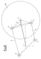
- a transmission system is shown in which an axis of a driven pulley does not coincide with a rotation axis of a driving-wheel.
- an engine exit axis 1 an axis 2 of the driven pulley and an axis 3 of a driving-wheel 10 are shown.
- the engine axis 1 is located on the engine (not shown), whereas the axis 2 of the driven pulley and the axis 3 of the driving-wheel 10 are located on the support cast (not shown) of the driving-wheel 10.
- connection between the engine and the driving wheel 10 is realised through an upper connection arm 4 and a lower connection arm 5, said arms being hinged, from the engine side, respectively at a first upper rotation axis 6 and at a first lower rotation axis 7 and, from the wheel side, respectively at a second upper rotation axis 8 and at a second lower rotation axis 9, said second axes being situated on the support structure of the driving-wheel 10.
- a parallelogram is defined, the sides of which have a constant length, being able, however to vary the size of the corresponding angles.
- the exit shaft of the engine 1, the first upper rotation axis 6 and the first lower rotation axis 7, all being fixed on the engine, are integral with each other.
Landscapes
- Engineering & Computer Science (AREA)
- Mechanical Engineering (AREA)
- Devices For Conveying Motion By Means Of Endless Flexible Members (AREA)
- Arrangement Or Mounting Of Propulsion Units For Vehicles (AREA)
Applications Claiming Priority (2)
| Application Number | Priority Date | Filing Date | Title |
|---|---|---|---|
| ITMI20031058 | 2003-05-27 | ||
| IT001058A ITMI20031058A1 (it) | 2003-05-27 | 2003-05-27 | Struttura di attacco tra ruota motrice e motore, in particolare per motoveicoli |
Publications (2)
| Publication Number | Publication Date |
|---|---|
| EP1481885A2 true EP1481885A2 (de) | 2004-12-01 |
| EP1481885A3 EP1481885A3 (de) | 2006-04-12 |
Family
ID=30131088
Family Applications (1)
| Application Number | Title | Priority Date | Filing Date |
|---|---|---|---|
| EP04076524A Withdrawn EP1481885A3 (de) | 2003-05-27 | 2004-05-24 | Verbindungsstruktur eines Antriebrads zum Motor, insbesondere für Kraftfahrzeuge |
Country Status (4)
| Country | Link |
|---|---|
| EP (1) | EP1481885A3 (de) |
| CN (1) | CN1572569A (de) |
| IT (1) | ITMI20031058A1 (de) |
| TW (1) | TW200505737A (de) |
Cited By (1)
| Publication number | Priority date | Publication date | Assignee | Title |
|---|---|---|---|---|
| FR2963312A1 (fr) * | 2010-08-02 | 2012-02-03 | Tecmas | Dispositif de liaison au sol pour suspension arriere et vehicule correspondant |
Citations (1)
| Publication number | Priority date | Publication date | Assignee | Title |
|---|---|---|---|---|
| EP0279763A2 (de) | 1987-02-20 | 1988-08-24 | José Luis Belil Creixell | Hinterradaufhängungsmechanismus für Motorfahrräder und ähnliche Fahrzeuge |
Family Cites Families (5)
| Publication number | Priority date | Publication date | Assignee | Title |
|---|---|---|---|---|
| GB767101A (en) * | 1953-09-16 | 1957-01-30 | Douglas Marshall | Improved rear wheel suspension for motor driven cycles |
| US4058181A (en) * | 1976-03-16 | 1977-11-15 | Buell Erik F | Motorcycle suspension systems |
| US4114918A (en) * | 1977-03-18 | 1978-09-19 | Parlec, Inc. | Suspension system for wheel of a motor bike |
| JPH01127475A (ja) * | 1987-11-13 | 1989-05-19 | Kawasaki Heavy Ind Ltd | 車両用駆動輪懸架装置 |
| BE1001347A3 (nl) * | 1988-01-07 | 1989-10-03 | Vel Alfons Van De | Wielophanging voor een via een eindloze overbrenging aangedreven wiel. |
-
2003
- 2003-05-27 IT IT001058A patent/ITMI20031058A1/it unknown
-
2004
- 2004-05-24 EP EP04076524A patent/EP1481885A3/de not_active Withdrawn
- 2004-05-24 TW TW093114623A patent/TW200505737A/zh unknown
- 2004-05-27 CN CN200410063930.8A patent/CN1572569A/zh active Pending
Patent Citations (1)
| Publication number | Priority date | Publication date | Assignee | Title |
|---|---|---|---|---|
| EP0279763A2 (de) | 1987-02-20 | 1988-08-24 | José Luis Belil Creixell | Hinterradaufhängungsmechanismus für Motorfahrräder und ähnliche Fahrzeuge |
Cited By (1)
| Publication number | Priority date | Publication date | Assignee | Title |
|---|---|---|---|---|
| FR2963312A1 (fr) * | 2010-08-02 | 2012-02-03 | Tecmas | Dispositif de liaison au sol pour suspension arriere et vehicule correspondant |
Also Published As
| Publication number | Publication date |
|---|---|
| EP1481885A3 (de) | 2006-04-12 |
| CN1572569A (zh) | 2005-02-02 |
| TW200505737A (en) | 2005-02-16 |
| ITMI20031058A0 (it) | 2003-05-27 |
| ITMI20031058A1 (it) | 2004-11-28 |
Similar Documents
| Publication | Publication Date | Title |
|---|---|---|
| EP0113333A1 (de) | Federnde Aufhängung für Hinterräder | |
| DE102004048246B4 (de) | Bremssattelträgerstruktur für ein Kraftrad | |
| FR2632597A1 (fr) | Transmission pour vehicule a au moins une roue motrice | |
| FR2533173B1 (fr) | Dispositif de bras support d'une roue motrice | |
| AU594707B2 (en) | Saddle type vehicle running on uneven ground | |
| CN103619697A (zh) | 作业车辆 | |
| US20180319095A1 (en) | Drive System for Automatic Welding Machine | |
| US7677346B2 (en) | Frame structure of motorcycle | |
| EP1043519A3 (de) | Zweifach Spannerssytem für Balancierwellenantrieb | |
| EP1481885A2 (de) | Verbindungsstruktur eines Antriebrads zum Motor, insbesondere für Kraftfahrzeuge | |
| EP3093395B1 (de) | Frontlader, frame mechanismus eines frontladers und verfahren | |
| CA2545835A1 (en) | System for converting a recreational vehicle | |
| JP3831531B2 (ja) | コンバインの走行装置 | |
| US20160143230A1 (en) | Feed wheel arrangement, timber working head, crane, and timber working machine | |
| SE438881B (sv) | Knelenkanordning vid skoplastare | |
| JP4671778B2 (ja) | 自動二輪車の後輪懸架装置 | |
| JPS59143787A (ja) | ベルト駆動式自動二輪車 | |
| JP2541783Y2 (ja) | 巻付防止装置 | |
| JPS601567Y2 (ja) | コンバインの前方刈取搬送部における機体構造 | |
| EP1481886B1 (de) | Kupplungssystem zwischen Rahmen und Hinteraufhängung/motor Gruppe eines Kraftfahrzeugs | |
| JPH0930226A (ja) | サスペンション部の配線構造 | |
| JPH0314418Y2 (de) | ||
| FR2963312A1 (fr) | Dispositif de liaison au sol pour suspension arriere et vehicule correspondant | |
| CN100471711C (zh) | 公共汽车冷却风扇的驱动系统 | |
| FR2430182A1 (fr) | Outil de travail agricole |
Legal Events
| Date | Code | Title | Description |
|---|---|---|---|
| PUAI | Public reference made under article 153(3) epc to a published international application that has entered the european phase |
Free format text: ORIGINAL CODE: 0009012 |
|
| AK | Designated contracting states |
Kind code of ref document: A2 Designated state(s): AT BE BG CH CY CZ DE DK EE ES FI FR GB GR HU IE IT LI LU MC NL PL PT RO SE SI SK TR |
|
| AX | Request for extension of the european patent |
Extension state: AL HR LT LV MK |
|
| PUAL | Search report despatched |
Free format text: ORIGINAL CODE: 0009013 |
|
| AK | Designated contracting states |
Kind code of ref document: A3 Designated state(s): AT BE BG CH CY CZ DE DK EE ES FI FR GB GR HU IE IT LI LU MC NL PL PT RO SE SI SK TR |
|
| AX | Request for extension of the european patent |
Extension state: AL HR LT LV MK |
|
| RIC1 | Information provided on ipc code assigned before grant |
Ipc: B62K 25/26 20060101ALI20060217BHEP Ipc: B62K 25/28 20060101AFI20040908BHEP |
|
| 17P | Request for examination filed |
Effective date: 20061003 |
|
| AKX | Designation fees paid |
Designated state(s): AT BE BG CH CY CZ DE DK EE ES FI FR GB GR HU IE IT LI LU MC NL PL PT RO SE SI SK TR |
|
| 17Q | First examination report despatched |
Effective date: 20070109 |
|
| STAA | Information on the status of an ep patent application or granted ep patent |
Free format text: STATUS: THE APPLICATION IS DEEMED TO BE WITHDRAWN |
|
| 18D | Application deemed to be withdrawn |
Effective date: 20091201 |