EP1481654A1 - Zwischenwirbelfusionsimplantat sowie Instrument zur Platzierung und Distraktion des Implantates - Google Patents
Zwischenwirbelfusionsimplantat sowie Instrument zur Platzierung und Distraktion des Implantates Download PDFInfo
- Publication number
- EP1481654A1 EP1481654A1 EP04009760A EP04009760A EP1481654A1 EP 1481654 A1 EP1481654 A1 EP 1481654A1 EP 04009760 A EP04009760 A EP 04009760A EP 04009760 A EP04009760 A EP 04009760A EP 1481654 A1 EP1481654 A1 EP 1481654A1
- Authority
- EP
- European Patent Office
- Prior art keywords
- implant
- implant part
- guide
- implant according
- instrument
- Prior art date
- Legal status (The legal status is an assumption and is not a legal conclusion. Google has not performed a legal analysis and makes no representation as to the accuracy of the status listed.)
- Granted
Links
Images


Classifications
-
- A—HUMAN NECESSITIES
- A61—MEDICAL OR VETERINARY SCIENCE; HYGIENE
- A61F—FILTERS IMPLANTABLE INTO BLOOD VESSELS; PROSTHESES; DEVICES PROVIDING PATENCY TO, OR PREVENTING COLLAPSING OF, TUBULAR STRUCTURES OF THE BODY, e.g. STENTS; ORTHOPAEDIC, NURSING OR CONTRACEPTIVE DEVICES; FOMENTATION; TREATMENT OR PROTECTION OF EYES OR EARS; BANDAGES, DRESSINGS OR ABSORBENT PADS; FIRST-AID KITS
- A61F2/00—Filters implantable into blood vessels; Prostheses, i.e. artificial substitutes or replacements for parts of the body; Appliances for connecting them with the body; Devices providing patency to, or preventing collapsing of, tubular structures of the body, e.g. stents
- A61F2/02—Prostheses implantable into the body
- A61F2/30—Joints
- A61F2/46—Special tools or methods for implanting or extracting artificial joints, accessories, bone grafts or substitutes, or particular adaptations therefor
- A61F2/4603—Special tools or methods for implanting or extracting artificial joints, accessories, bone grafts or substitutes, or particular adaptations therefor for insertion or extraction of endoprosthetic joints or of accessories thereof
- A61F2/4611—Special tools or methods for implanting or extracting artificial joints, accessories, bone grafts or substitutes, or particular adaptations therefor for insertion or extraction of endoprosthetic joints or of accessories thereof of spinal prostheses
-
- A—HUMAN NECESSITIES
- A61—MEDICAL OR VETERINARY SCIENCE; HYGIENE
- A61F—FILTERS IMPLANTABLE INTO BLOOD VESSELS; PROSTHESES; DEVICES PROVIDING PATENCY TO, OR PREVENTING COLLAPSING OF, TUBULAR STRUCTURES OF THE BODY, e.g. STENTS; ORTHOPAEDIC, NURSING OR CONTRACEPTIVE DEVICES; FOMENTATION; TREATMENT OR PROTECTION OF EYES OR EARS; BANDAGES, DRESSINGS OR ABSORBENT PADS; FIRST-AID KITS
- A61F2/00—Filters implantable into blood vessels; Prostheses, i.e. artificial substitutes or replacements for parts of the body; Appliances for connecting them with the body; Devices providing patency to, or preventing collapsing of, tubular structures of the body, e.g. stents
- A61F2/02—Prostheses implantable into the body
- A61F2/30—Joints
- A61F2/44—Joints for the spine, e.g. vertebrae, spinal discs
- A61F2/4455—Joints for the spine, e.g. vertebrae, spinal discs for the fusion of spinal bodies, e.g. intervertebral fusion of adjacent spinal bodies, e.g. fusion cages
- A61F2/446—Joints for the spine, e.g. vertebrae, spinal discs for the fusion of spinal bodies, e.g. intervertebral fusion of adjacent spinal bodies, e.g. fusion cages having a circular or elliptical cross-section substantially parallel to the axis of the spine, e.g. cylinders or frustocones
-
- A—HUMAN NECESSITIES
- A61—MEDICAL OR VETERINARY SCIENCE; HYGIENE
- A61F—FILTERS IMPLANTABLE INTO BLOOD VESSELS; PROSTHESES; DEVICES PROVIDING PATENCY TO, OR PREVENTING COLLAPSING OF, TUBULAR STRUCTURES OF THE BODY, e.g. STENTS; ORTHOPAEDIC, NURSING OR CONTRACEPTIVE DEVICES; FOMENTATION; TREATMENT OR PROTECTION OF EYES OR EARS; BANDAGES, DRESSINGS OR ABSORBENT PADS; FIRST-AID KITS
- A61F2/00—Filters implantable into blood vessels; Prostheses, i.e. artificial substitutes or replacements for parts of the body; Appliances for connecting them with the body; Devices providing patency to, or preventing collapsing of, tubular structures of the body, e.g. stents
- A61F2/02—Prostheses implantable into the body
- A61F2/30—Joints
- A61F2002/30001—Additional features of subject-matter classified in A61F2/28, A61F2/30 and subgroups thereof
- A61F2002/30108—Shapes
- A61F2002/30199—Three-dimensional shapes
- A61F2002/30224—Three-dimensional shapes cylindrical
- A61F2002/30235—Three-dimensional shapes cylindrical tubular, e.g. sleeves
- A61F2002/30237—Three-dimensional shapes cylindrical tubular, e.g. sleeves partial tubes
-
- A—HUMAN NECESSITIES
- A61—MEDICAL OR VETERINARY SCIENCE; HYGIENE
- A61F—FILTERS IMPLANTABLE INTO BLOOD VESSELS; PROSTHESES; DEVICES PROVIDING PATENCY TO, OR PREVENTING COLLAPSING OF, TUBULAR STRUCTURES OF THE BODY, e.g. STENTS; ORTHOPAEDIC, NURSING OR CONTRACEPTIVE DEVICES; FOMENTATION; TREATMENT OR PROTECTION OF EYES OR EARS; BANDAGES, DRESSINGS OR ABSORBENT PADS; FIRST-AID KITS
- A61F2/00—Filters implantable into blood vessels; Prostheses, i.e. artificial substitutes or replacements for parts of the body; Appliances for connecting them with the body; Devices providing patency to, or preventing collapsing of, tubular structures of the body, e.g. stents
- A61F2/02—Prostheses implantable into the body
- A61F2/30—Joints
- A61F2002/30001—Additional features of subject-matter classified in A61F2/28, A61F2/30 and subgroups thereof
- A61F2002/30316—The prosthesis having different structural features at different locations within the same prosthesis; Connections between prosthetic parts; Special structural features of bone or joint prostheses not otherwise provided for
- A61F2002/30329—Connections or couplings between prosthetic parts, e.g. between modular parts; Connecting elements
- A61F2002/30476—Connections or couplings between prosthetic parts, e.g. between modular parts; Connecting elements locked by an additional locking mechanism
- A61F2002/30507—Connections or couplings between prosthetic parts, e.g. between modular parts; Connecting elements locked by an additional locking mechanism using a threaded locking member, e.g. a locking screw or a set screw
-
- A—HUMAN NECESSITIES
- A61—MEDICAL OR VETERINARY SCIENCE; HYGIENE
- A61F—FILTERS IMPLANTABLE INTO BLOOD VESSELS; PROSTHESES; DEVICES PROVIDING PATENCY TO, OR PREVENTING COLLAPSING OF, TUBULAR STRUCTURES OF THE BODY, e.g. STENTS; ORTHOPAEDIC, NURSING OR CONTRACEPTIVE DEVICES; FOMENTATION; TREATMENT OR PROTECTION OF EYES OR EARS; BANDAGES, DRESSINGS OR ABSORBENT PADS; FIRST-AID KITS
- A61F2/00—Filters implantable into blood vessels; Prostheses, i.e. artificial substitutes or replacements for parts of the body; Appliances for connecting them with the body; Devices providing patency to, or preventing collapsing of, tubular structures of the body, e.g. stents
- A61F2/02—Prostheses implantable into the body
- A61F2/30—Joints
- A61F2002/30001—Additional features of subject-matter classified in A61F2/28, A61F2/30 and subgroups thereof
- A61F2002/30316—The prosthesis having different structural features at different locations within the same prosthesis; Connections between prosthetic parts; Special structural features of bone or joint prostheses not otherwise provided for
- A61F2002/30535—Special structural features of bone or joint prostheses not otherwise provided for
- A61F2002/30537—Special structural features of bone or joint prostheses not otherwise provided for adjustable
- A61F2002/3055—Special structural features of bone or joint prostheses not otherwise provided for adjustable for adjusting length
-
- A—HUMAN NECESSITIES
- A61—MEDICAL OR VETERINARY SCIENCE; HYGIENE
- A61F—FILTERS IMPLANTABLE INTO BLOOD VESSELS; PROSTHESES; DEVICES PROVIDING PATENCY TO, OR PREVENTING COLLAPSING OF, TUBULAR STRUCTURES OF THE BODY, e.g. STENTS; ORTHOPAEDIC, NURSING OR CONTRACEPTIVE DEVICES; FOMENTATION; TREATMENT OR PROTECTION OF EYES OR EARS; BANDAGES, DRESSINGS OR ABSORBENT PADS; FIRST-AID KITS
- A61F2/00—Filters implantable into blood vessels; Prostheses, i.e. artificial substitutes or replacements for parts of the body; Appliances for connecting them with the body; Devices providing patency to, or preventing collapsing of, tubular structures of the body, e.g. stents
- A61F2/02—Prostheses implantable into the body
- A61F2/30—Joints
- A61F2002/30001—Additional features of subject-matter classified in A61F2/28, A61F2/30 and subgroups thereof
- A61F2002/30316—The prosthesis having different structural features at different locations within the same prosthesis; Connections between prosthetic parts; Special structural features of bone or joint prostheses not otherwise provided for
- A61F2002/30535—Special structural features of bone or joint prostheses not otherwise provided for
- A61F2002/30537—Special structural features of bone or joint prostheses not otherwise provided for adjustable
- A61F2002/30556—Special structural features of bone or joint prostheses not otherwise provided for adjustable for adjusting thickness
-
- A—HUMAN NECESSITIES
- A61—MEDICAL OR VETERINARY SCIENCE; HYGIENE
- A61F—FILTERS IMPLANTABLE INTO BLOOD VESSELS; PROSTHESES; DEVICES PROVIDING PATENCY TO, OR PREVENTING COLLAPSING OF, TUBULAR STRUCTURES OF THE BODY, e.g. STENTS; ORTHOPAEDIC, NURSING OR CONTRACEPTIVE DEVICES; FOMENTATION; TREATMENT OR PROTECTION OF EYES OR EARS; BANDAGES, DRESSINGS OR ABSORBENT PADS; FIRST-AID KITS
- A61F2/00—Filters implantable into blood vessels; Prostheses, i.e. artificial substitutes or replacements for parts of the body; Appliances for connecting them with the body; Devices providing patency to, or preventing collapsing of, tubular structures of the body, e.g. stents
- A61F2/02—Prostheses implantable into the body
- A61F2/30—Joints
- A61F2002/30001—Additional features of subject-matter classified in A61F2/28, A61F2/30 and subgroups thereof
- A61F2002/30316—The prosthesis having different structural features at different locations within the same prosthesis; Connections between prosthetic parts; Special structural features of bone or joint prostheses not otherwise provided for
- A61F2002/30535—Special structural features of bone or joint prostheses not otherwise provided for
- A61F2002/30601—Special structural features of bone or joint prostheses not otherwise provided for telescopic
-
- A—HUMAN NECESSITIES
- A61—MEDICAL OR VETERINARY SCIENCE; HYGIENE
- A61F—FILTERS IMPLANTABLE INTO BLOOD VESSELS; PROSTHESES; DEVICES PROVIDING PATENCY TO, OR PREVENTING COLLAPSING OF, TUBULAR STRUCTURES OF THE BODY, e.g. STENTS; ORTHOPAEDIC, NURSING OR CONTRACEPTIVE DEVICES; FOMENTATION; TREATMENT OR PROTECTION OF EYES OR EARS; BANDAGES, DRESSINGS OR ABSORBENT PADS; FIRST-AID KITS
- A61F2/00—Filters implantable into blood vessels; Prostheses, i.e. artificial substitutes or replacements for parts of the body; Appliances for connecting them with the body; Devices providing patency to, or preventing collapsing of, tubular structures of the body, e.g. stents
- A61F2/02—Prostheses implantable into the body
- A61F2/30—Joints
- A61F2/30767—Special external or bone-contacting surface, e.g. coating for improving bone ingrowth
- A61F2/30771—Special external or bone-contacting surface, e.g. coating for improving bone ingrowth applied in original prostheses, e.g. holes or grooves
- A61F2002/30878—Special external or bone-contacting surface, e.g. coating for improving bone ingrowth applied in original prostheses, e.g. holes or grooves with non-sharp protrusions, for instance contacting the bone for anchoring, e.g. keels, pegs, pins, posts, shanks, stems, struts
- A61F2002/30879—Ribs
- A61F2002/30881—Circumferential ribs, flanges or fins
-
- A—HUMAN NECESSITIES
- A61—MEDICAL OR VETERINARY SCIENCE; HYGIENE
- A61F—FILTERS IMPLANTABLE INTO BLOOD VESSELS; PROSTHESES; DEVICES PROVIDING PATENCY TO, OR PREVENTING COLLAPSING OF, TUBULAR STRUCTURES OF THE BODY, e.g. STENTS; ORTHOPAEDIC, NURSING OR CONTRACEPTIVE DEVICES; FOMENTATION; TREATMENT OR PROTECTION OF EYES OR EARS; BANDAGES, DRESSINGS OR ABSORBENT PADS; FIRST-AID KITS
- A61F2/00—Filters implantable into blood vessels; Prostheses, i.e. artificial substitutes or replacements for parts of the body; Appliances for connecting them with the body; Devices providing patency to, or preventing collapsing of, tubular structures of the body, e.g. stents
- A61F2/02—Prostheses implantable into the body
- A61F2/30—Joints
- A61F2/44—Joints for the spine, e.g. vertebrae, spinal discs
- A61F2002/448—Joints for the spine, e.g. vertebrae, spinal discs comprising multiple adjacent spinal implants within the same intervertebral space or within the same vertebra, e.g. comprising two adjacent spinal implants
-
- A—HUMAN NECESSITIES
- A61—MEDICAL OR VETERINARY SCIENCE; HYGIENE
- A61F—FILTERS IMPLANTABLE INTO BLOOD VESSELS; PROSTHESES; DEVICES PROVIDING PATENCY TO, OR PREVENTING COLLAPSING OF, TUBULAR STRUCTURES OF THE BODY, e.g. STENTS; ORTHOPAEDIC, NURSING OR CONTRACEPTIVE DEVICES; FOMENTATION; TREATMENT OR PROTECTION OF EYES OR EARS; BANDAGES, DRESSINGS OR ABSORBENT PADS; FIRST-AID KITS
- A61F2/00—Filters implantable into blood vessels; Prostheses, i.e. artificial substitutes or replacements for parts of the body; Appliances for connecting them with the body; Devices providing patency to, or preventing collapsing of, tubular structures of the body, e.g. stents
- A61F2/02—Prostheses implantable into the body
- A61F2/30—Joints
- A61F2/46—Special tools or methods for implanting or extracting artificial joints, accessories, bone grafts or substitutes, or particular adaptations therefor
- A61F2/4603—Special tools or methods for implanting or extracting artificial joints, accessories, bone grafts or substitutes, or particular adaptations therefor for insertion or extraction of endoprosthetic joints or of accessories thereof
- A61F2002/4625—Special tools or methods for implanting or extracting artificial joints, accessories, bone grafts or substitutes, or particular adaptations therefor for insertion or extraction of endoprosthetic joints or of accessories thereof with relative movement between parts of the instrument during use
- A61F2002/4627—Special tools or methods for implanting or extracting artificial joints, accessories, bone grafts or substitutes, or particular adaptations therefor for insertion or extraction of endoprosthetic joints or of accessories thereof with relative movement between parts of the instrument during use with linear motion along or rotating motion about the instrument axis or the implantation direction, e.g. telescopic, along a guiding rod, screwing inside the instrument
-
- A—HUMAN NECESSITIES
- A61—MEDICAL OR VETERINARY SCIENCE; HYGIENE
- A61F—FILTERS IMPLANTABLE INTO BLOOD VESSELS; PROSTHESES; DEVICES PROVIDING PATENCY TO, OR PREVENTING COLLAPSING OF, TUBULAR STRUCTURES OF THE BODY, e.g. STENTS; ORTHOPAEDIC, NURSING OR CONTRACEPTIVE DEVICES; FOMENTATION; TREATMENT OR PROTECTION OF EYES OR EARS; BANDAGES, DRESSINGS OR ABSORBENT PADS; FIRST-AID KITS
- A61F2/00—Filters implantable into blood vessels; Prostheses, i.e. artificial substitutes or replacements for parts of the body; Appliances for connecting them with the body; Devices providing patency to, or preventing collapsing of, tubular structures of the body, e.g. stents
- A61F2/02—Prostheses implantable into the body
- A61F2/30—Joints
- A61F2/46—Special tools or methods for implanting or extracting artificial joints, accessories, bone grafts or substitutes, or particular adaptations therefor
- A61F2/4603—Special tools or methods for implanting or extracting artificial joints, accessories, bone grafts or substitutes, or particular adaptations therefor for insertion or extraction of endoprosthetic joints or of accessories thereof
- A61F2002/4629—Special tools or methods for implanting or extracting artificial joints, accessories, bone grafts or substitutes, or particular adaptations therefor for insertion or extraction of endoprosthetic joints or of accessories thereof connected to the endoprosthesis or implant via a threaded connection
-
- A—HUMAN NECESSITIES
- A61—MEDICAL OR VETERINARY SCIENCE; HYGIENE
- A61F—FILTERS IMPLANTABLE INTO BLOOD VESSELS; PROSTHESES; DEVICES PROVIDING PATENCY TO, OR PREVENTING COLLAPSING OF, TUBULAR STRUCTURES OF THE BODY, e.g. STENTS; ORTHOPAEDIC, NURSING OR CONTRACEPTIVE DEVICES; FOMENTATION; TREATMENT OR PROTECTION OF EYES OR EARS; BANDAGES, DRESSINGS OR ABSORBENT PADS; FIRST-AID KITS
- A61F2/00—Filters implantable into blood vessels; Prostheses, i.e. artificial substitutes or replacements for parts of the body; Appliances for connecting them with the body; Devices providing patency to, or preventing collapsing of, tubular structures of the body, e.g. stents
- A61F2/02—Prostheses implantable into the body
- A61F2/30—Joints
- A61F2/46—Special tools or methods for implanting or extracting artificial joints, accessories, bone grafts or substitutes, or particular adaptations therefor
- A61F2002/4635—Special tools or methods for implanting or extracting artificial joints, accessories, bone grafts or substitutes, or particular adaptations therefor using minimally invasive surgery
-
- A—HUMAN NECESSITIES
- A61—MEDICAL OR VETERINARY SCIENCE; HYGIENE
- A61F—FILTERS IMPLANTABLE INTO BLOOD VESSELS; PROSTHESES; DEVICES PROVIDING PATENCY TO, OR PREVENTING COLLAPSING OF, TUBULAR STRUCTURES OF THE BODY, e.g. STENTS; ORTHOPAEDIC, NURSING OR CONTRACEPTIVE DEVICES; FOMENTATION; TREATMENT OR PROTECTION OF EYES OR EARS; BANDAGES, DRESSINGS OR ABSORBENT PADS; FIRST-AID KITS
- A61F2220/00—Fixations or connections for prostheses classified in groups A61F2/00 - A61F2/26 or A61F2/82 or A61F9/00 or A61F11/00 or subgroups thereof
- A61F2220/0025—Connections or couplings between prosthetic parts, e.g. between modular parts; Connecting elements
-
- A—HUMAN NECESSITIES
- A61—MEDICAL OR VETERINARY SCIENCE; HYGIENE
- A61F—FILTERS IMPLANTABLE INTO BLOOD VESSELS; PROSTHESES; DEVICES PROVIDING PATENCY TO, OR PREVENTING COLLAPSING OF, TUBULAR STRUCTURES OF THE BODY, e.g. STENTS; ORTHOPAEDIC, NURSING OR CONTRACEPTIVE DEVICES; FOMENTATION; TREATMENT OR PROTECTION OF EYES OR EARS; BANDAGES, DRESSINGS OR ABSORBENT PADS; FIRST-AID KITS
- A61F2230/00—Geometry of prostheses classified in groups A61F2/00 - A61F2/26 or A61F2/82 or A61F9/00 or A61F11/00 or subgroups thereof
- A61F2230/0063—Three-dimensional shapes
- A61F2230/0069—Three-dimensional shapes cylindrical
-
- A—HUMAN NECESSITIES
- A61—MEDICAL OR VETERINARY SCIENCE; HYGIENE
- A61F—FILTERS IMPLANTABLE INTO BLOOD VESSELS; PROSTHESES; DEVICES PROVIDING PATENCY TO, OR PREVENTING COLLAPSING OF, TUBULAR STRUCTURES OF THE BODY, e.g. STENTS; ORTHOPAEDIC, NURSING OR CONTRACEPTIVE DEVICES; FOMENTATION; TREATMENT OR PROTECTION OF EYES OR EARS; BANDAGES, DRESSINGS OR ABSORBENT PADS; FIRST-AID KITS
- A61F2250/00—Special features of prostheses classified in groups A61F2/00 - A61F2/26 or A61F2/82 or A61F9/00 or A61F11/00 or subgroups thereof
- A61F2250/0004—Special features of prostheses classified in groups A61F2/00 - A61F2/26 or A61F2/82 or A61F9/00 or A61F11/00 or subgroups thereof adjustable
- A61F2250/0009—Special features of prostheses classified in groups A61F2/00 - A61F2/26 or A61F2/82 or A61F9/00 or A61F11/00 or subgroups thereof adjustable for adjusting thickness
-
- A—HUMAN NECESSITIES
- A61—MEDICAL OR VETERINARY SCIENCE; HYGIENE
- A61F—FILTERS IMPLANTABLE INTO BLOOD VESSELS; PROSTHESES; DEVICES PROVIDING PATENCY TO, OR PREVENTING COLLAPSING OF, TUBULAR STRUCTURES OF THE BODY, e.g. STENTS; ORTHOPAEDIC, NURSING OR CONTRACEPTIVE DEVICES; FOMENTATION; TREATMENT OR PROTECTION OF EYES OR EARS; BANDAGES, DRESSINGS OR ABSORBENT PADS; FIRST-AID KITS
- A61F2310/00—Prostheses classified in A61F2/28 or A61F2/30 - A61F2/44 being constructed from or coated with a particular material
- A61F2310/00005—The prosthesis being constructed from a particular material
- A61F2310/00011—Metals or alloys
- A61F2310/00017—Iron- or Fe-based alloys, e.g. stainless steel
-
- A—HUMAN NECESSITIES
- A61—MEDICAL OR VETERINARY SCIENCE; HYGIENE
- A61F—FILTERS IMPLANTABLE INTO BLOOD VESSELS; PROSTHESES; DEVICES PROVIDING PATENCY TO, OR PREVENTING COLLAPSING OF, TUBULAR STRUCTURES OF THE BODY, e.g. STENTS; ORTHOPAEDIC, NURSING OR CONTRACEPTIVE DEVICES; FOMENTATION; TREATMENT OR PROTECTION OF EYES OR EARS; BANDAGES, DRESSINGS OR ABSORBENT PADS; FIRST-AID KITS
- A61F2310/00—Prostheses classified in A61F2/28 or A61F2/30 - A61F2/44 being constructed from or coated with a particular material
- A61F2310/00005—The prosthesis being constructed from a particular material
- A61F2310/00011—Metals or alloys
- A61F2310/00023—Titanium or titanium-based alloys, e.g. Ti-Ni alloys
-
- A—HUMAN NECESSITIES
- A61—MEDICAL OR VETERINARY SCIENCE; HYGIENE
- A61F—FILTERS IMPLANTABLE INTO BLOOD VESSELS; PROSTHESES; DEVICES PROVIDING PATENCY TO, OR PREVENTING COLLAPSING OF, TUBULAR STRUCTURES OF THE BODY, e.g. STENTS; ORTHOPAEDIC, NURSING OR CONTRACEPTIVE DEVICES; FOMENTATION; TREATMENT OR PROTECTION OF EYES OR EARS; BANDAGES, DRESSINGS OR ABSORBENT PADS; FIRST-AID KITS
- A61F2310/00—Prostheses classified in A61F2/28 or A61F2/30 - A61F2/44 being constructed from or coated with a particular material
- A61F2310/00005—The prosthesis being constructed from a particular material
- A61F2310/00353—Bone cement, e.g. polymethylmethacrylate or PMMA
Definitions
- the invention relates to an implant for intersomatic Fusion of two adjacent vertebrae, with a first Implant part and one opposite to this for distraction adjustable second implant part.
- Implants for the intersomatic fusion of two vertebrae are used to search for what is deemed necessary Resection of an intervertebral disc the affected segment of the Stabilize spine.
- the surgical procedures one differentiates with regard to the access to the Spine from the back or from the abdomen different surgical techniques for which basically different framework conditions apply.
- the necessary measures to Removal of the intervertebral disc, preparation of the vertebrae and inserting the implant in the immediate vicinity of the Spinal cord take place and the surgeon with little space has to get by.
- the invention is therefore based on the object Design the implant of the type mentioned at the outset in such a way that with full preservation of the distraction option and ease of use of the implant Distraction in the operating field in situ the design reduced, in particular the length can be reduced.
- first Implant part and the second implant part designed in this way are that they complement each other in the undistracted Complement the condition to a pipe divided in the longitudinal direction, that on the first implant part and on the second implant part extending radially, in the direction of distraction, mutually abutting guide surfaces are formed, and that means to fix the relative location of the Guide surfaces are provided.
- the tube in the non-distracted state a circular Has cross-sectional shape and forms a cylinder.
- the Cylinder is characterized by its easy to manufacture, simple geometric shape made with a high Resilience is connected.
- the guide surface of the first implant part on the end face and the Guide surface of the second implant part in a radial extending slot is formed, namely on the Inside of a face plate. This ensures that for the precisely defined adjustment of the two Implant parts and for their mutual fixation required components radially from the surface of the Rohrers extend inwards and thus when inserting the Implant for these components no increased space requirements is required.
- the slot when the slot is radial towards the first Implant part expands when the face plate is in two parts formed with the second implant part and in axial Direction is adjustable, and if the guide surface of the first implant part on one in the slot engaging guide wedge with parallel to the Slotted walls extending wedge walls is formed.
- This configuration can be done in a simple manner Clamping the relative position of the two implant parts fixed to each other and also released again, whereby through the slot and through the guide wedge at one Loading the implant itself is a reinforcement of the Fixation results because the guide wedge in the slot is pressed in and with its wedge walls Contact pressure between the guide surfaces increased and thus increases the frictional engagement.
- an axially extending guide groove in the end plate is designed to interact with one at the second implant part trained guide pin because so also the axial adjustment of the two implant parts relative to each other in a precisely defined manner.
- the guide wedge in the circumferential direction as one-sided open Ring is designed with its ring opening in non-distracted state engages around the guide pin.
- first implant part and the second implant part surgical steel and / or titanium are formed.
- first implant part Alternatively or is also suitable as a means for fixation in addition between the first implant part and the second Bone cement to be inserted into the implant.
- a hollow rod on a handle connected at its front free end has pivotable actuator which has two pins for Insert in the two assigned to the longitudinal division Guide grooves that a on the hollow rod Sleeve is connected with a pivot lever, which is the Actuation of one on the actuator for pivoting attacking pull piece and that in the hollow rod a hollow screwdriver is arranged, the one Set screw for screwing into the threaded hole of the Reaches through the screw head.
- This instrument can be used in the implant can be easily placed by the Pins are inserted into the guide grooves and the Screwdriver in contact with the grub screw is brought with the screw head in such a way that the The set screw is screwed into the threaded hole Absorption of tensile forces and the screwdriver in usually only in a positive fit the screw head is applied to exert rotational forces on the screw can.
- the two guide surfaces of the two implant parts mutually displaceable, the displacement is effected by operating the swivel lever, the one Rotation of the actuator causes that by its two Pins an expansion of the guide grooves perpendicular to Slitting created with the resulting Adjustment of the two implant parts relative to each other. This adjustment can be fixed again by actuating the locking screw using the Screwdriver.
- a hollow thread is formed with the hollow rod one to limit the travel of the sleeve arranged threaded ring.
- a bracket is mounted on the handle, the between an the axial adjustment path of the grub screw limiting position and a limitation canceling position is pivotable.
- the drawing shows an implant 1 which is used for intersomatic fusion of two adjacent vertebrae 2 is used when access to the spine preferably from posterior.
- the implant 1 consists of a first implant part 3 and a compared to this second adjustable for distraction Implant part 4, the first implant part 3 and the second implant part 4 are designed so that they are complementary in an undistracted state to an in Longitudinally divided tube 5 of circular Complete cross-sectional shape, i.e. a cylinder.
- the guide surface 6 of the first Implant part 3 on its end face 7 and Guide surface 6 of the second implant part 4 on one radially extending slot 8 on the inside of a End plate 9 is formed, the two parts with the second implant part 4 is formed.
- the slot 8 expands radially towards the first Implant part 3; the guide surface 6 of the first Implant part 3 is on one in the slot 8 engaging guide wedge 10 with parallel to the Slotted walls formed wedge walls.
- the End plate 9 has an axially extending guide groove 11 on that to interact with one on the second Implant part 4 formed guide pin 12 is provided is.
- the guide wedge 10 is in the circumferential direction as one-sided open ring designed with its Ring opening 13 in the undistracted state Grips guide pin 12.
- the implant 1 also has a means for fixation the relative position of the first implant part 3 and the second implant part 4, one in the end plate 9 formed on the inward-facing side, axially running threaded bore 14 and one on the second Implant part 4 formed ring eye 15, the Ring eyelet 15 serves one in the threaded bore 14 to hold engaging locking screw 16.
- This Locking screw 16 is through an implant opening 17 accessible on the face 7 opposite side of the implant 1 is present.
- An alternative not shown in the drawing uses as a means of fixing bone cement between the first implant part 3 and second implant part 4 is introduced and after curing as a solid core fills and stiffens the implant part 1.
- the paired use shown in Figure 20 of the implant 1 is preferred, but not mandatory, because the resilience of the implant 1 is so high that at corresponding indication and access only one implant can be used.
- the instrument 19 has one on a handle 20 connected hollow rod 21 on its front free end has a pivotable actuator 22 which two pins 23 for insertion into the two of the Longitudinal division associated guide grooves 18, wherein on the hollow rod 21, a sleeve 24 with a Swivel lever 25 is connected to the actuation one acting on the actuator 22 for pivoting Pull piece 26 is used.
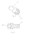
- a hollow screwdriver 27 arranged the one Set screw 28 for screwing into a threaded bore 29 of the screw head of the locking screw 16.
- a Rod thread 20 formed with a limit thereon the travel of the sleeve 24 arranged threaded ring 31st
- the pull piece 26 engages at the upper end of the Actuator 22, wherein on the hollow rod 21 in front area on the opposite bar walls Lugs 32 are formed which are perpendicular to the Longitudinal division of the implant 1 lying pivot axis define, with the actuator 22 at a distance from it Connection with the tension piece 26 abuts the lugs.
- a bracket 33 mounted between one limit the axial adjustment path of the grub screw Position and a position that removes this limitation is pivotable.
Abstract
Description
- Fig. 1
- eine perspektivische Darstellung eines erfindungsgemäßen Implantats,
- Fig. 2
- eine Seitenansicht des Implantats aus Fig. 1,
- Fig. 3
- eine Ansicht der Stirnseite des Implantats aus Fig. 1,
- Fig. 4
- eine Draufsicht auf das Implantat gem. Fig. 1,
- Fig. 5
- eine Darstellung der Unterseite des Implantats aus Fig. 1,
- Fig. 6
- eine der Fig. 1 entsprechenden Darstellung eines distrahierten Implantats,
- Fig. 7
- eine der Fig. 2 entsprechende Darstellung des Implantats aus Fig. 6,
- Fig. 8
- eine der Fig. 3 entsprechenden Darstellung des Implantates aus Fig. 6,
- Fig. 9
- eine der Fig. 5 entsprechende Darstellung des Implantats aus Fig. 6,
- Fig. 10
- eine perspektivische Darstellung des isolierten ersten Implantatteils,
- Fig. 11
- eine Stirnansicht des ersten Implantatteils aus Fig. 10,
- Fig. 12
- eine perspektivische Darstellung des isolierten zweiten Implantatteils,
- Fig. 13
- eine Stirnansicht des zweiten Implantatteils aus Fig. 12,
- Fig. 14
- eine Draufsicht auf das zweite Implantatteil aus Fig. 12,
- Fig. 15
- eine perspektivische Darstellung der isolierten Stirnplatte,
- Fig. 16
- eine Seitenansicht der Stirnplatte aus Fig. 15,
- Fig. 17
- eine schematische Darstellung der Wirbelsäule mit dem Rückenmarkskanal, wie diese sich nach Freilegung dem Operateur bei einem Zugang von posterior darstellt,
- Fig. 18
- eine der Fig. 17 entsprechende Darstellung zur Verdeutlichung der Schwierigkeiten zur Schaffung eines angemessenen Platzes während der Operation,
- Fig. 19
- eine Seitenansicht eines distrahierten, zwischen zwei Wirbelkörper eingesetzten Implantats,
- Fig. 20
- eine Draufsicht auf zwei auf der Deckplatte eines Wirbelkörpers platzierte erfindungsgemäße Implantate,
- Fig. 21
- eine der Fig. 19 entsprechende Darstellung mit dem angedeuteten Platzbedarf eines aus dem Stand der Technik bekannten Implantates,
- Fig. 22
- eine der Fig. 20 ensprechende Darstellung, in der das obere erfindungsgemäße Implantat ersetzt ist durch eine Andeutung des bei einem aus dem Stand der Technik bekannten Implantats erforderlichen Platzbedarfes,
- Fig. 23
- eine Seitenansicht eines mit dem Instrument in den Zwischenwirbelraum eingesetzten Implantats im nicht-distrahierten Zustand, dargestellt ohne Bügel,
- Fig. 24
- eine der Fig. 23 entsprechende Darstellung während der Distraktion des Implantats mittels des Instrumentes,
- Fig. 25
- eine Draufsicht auf das Implantat und das Instrument aus Fig. 23,
- Fig. 26
- eine perspektivische Darstellung des auf das Instrument aufgesetzten Implantats,
- Fig. 27
- eine der Fig. 26 ensprechende Darstellung mit dem Bügel in der zweiten Stellung,
- Fig. 28
- eine Seitenansicht des auf das Instrument aufgesetzten Implantats,
- Fig. 29
- eine der Fig. 28 entsprechende Darstellung eines isolierten Instruments,
- Fig. 30
- eine Seitenansicht der Einzelteile eines zerlegten Instruments,
- Fig. 31
- eine perspektivische Darstellung der Sicherungsschraube, und
- Fig. 32
- einen Längsschnitt durch die Sicherungsschraube aus Fig. 31.
Claims (18)
- Implantat zur intersomatischen Fusion zweier benachbarter Wirbel (2), mit einem ersten Implantatteil (3) und einem gegenüber diesem zur Distraktion verstellbaren zweiten Implantatteil (4), dadurch gekennzeichnet, daß das erste Implantatteil (3) und das zweite Implantatteil (4) so gestaltet sind, daß diese sich komplementär im nicht-distrahierten Zustand zu einem in Längsrichtung geteilten Rohr (5) ergänzen, daß am ersten Implantatteil (3) und am zweiten Implantatteil (4) sich radial, in Distraktionsrichtung erstreckende, einander anliegende Führungsflächen (6) ausgebildet sind, und daß Mittel zur Fixierung der relativen Lage der Führungsflächen (6) vorgesehen sind.
- Implantat nach Anspruch 1, dadurch gekennzeichnet, daß das Rohr (5) im nicht-distrahierten Zustand eine kreisrunde Querschnittsgestalt besitzt und einen Zylinder bildet.
- Implantat nach Anspruch 1 oder 2, dadurch gekennzeichnet, daß die Führungsfläche (6) des ersten Implantatteils (3) an dessen Stirnfläche (7) und die Führungsfläche (6) des zweiten Implantatteils (4) in einem radial verlaufenden Schlitz (8) ausgebildet ist.
- Implantat nach Anspruch 3, dadurch gekennzeichnet, daß die Führungsfläche (6) des zweiten Implantatteils (4) an der Innenseite einer Stirnplatte (9) ausgebildet ist.
- Implantat nach Anspruch 4, dadurch gekennzeichnet, daß der Schlitz (8) sich radial in Richtung des ersten Implantatteils (3) erweitert, daß die Stirnplatte (9) zweiteilig mit dem zweiten Implantatteil (4) ausgebildet und in axialer Richtung verstellbar ist, und daß die Führungsfläche (6) des ersten Implantatteils (3) an einem in den Schlitz (8) eingreifenden Führungskeil (10) mit parallel zu den Schlitzwänden (8) verlaufenden Keilwänden ausgebildet ist.
- Implantat nach Anspruch 5, dadurch gekennzeichnet, daß in der Stirnplatte (9) eine axial verlaufende Führungsnut (11) ausgebildet ist zum Zusammenwirken mit einem an dem zweiten Implantatteil (4) ausgebildeten Führungszapfen (12).
- Implantat nach Anspruch 6, dadurch gekennzeichnet, daß der Führungskeil (10) in Umfangsrichtung als einseitig offener Ring gestaltet ist, der mit seiner Ringöffnung (13) im nicht-distrahierten Zustand den Führungszapfen (12) umgreift.
- Implantat nach einem der Ansprüche 5 bis 7, dadurch gekennzeichnet, daß als Mittel zur Fixierung der relativen Lage des ersten Implantatteils (3) und des zweiten Implanttatteils (4) in der Stirnplatte (9) auf der nach innen weisenden Seite eine axial verlaufende Gewindebohrung (14) und an dem zweiten Implantatteil (4) eine Ringöse (15) ausgebildet ist zum Halten einer in die Gewindebohrung (14) eingreifenden Sicherungsschraube (16).
- Implantat nach einem der Ansprüche 3 bis 8, dadurch gekennzeichnet, daß auf der der Stirnfläche (7) gegenüberliegenden Seite eine Implantatöffnung (17) für den Zugang in das Implantatinnere ausgebildet ist.
- Implantat nach Anspruch 9, dadurch gekennzeichnet, daß in der Implantatöffnung (17) eine Mehrzahl von Führungsnuten (18) ausgebildet sind, von denen zwei entlang der Längsteilung zwischen dem ersten Implantatteil (3) und dem zweiten Implantatteil (4) verlaufen.
- Implantat nach Anspruch 9 oder 10, dadurch gekennzeichnet, daß in dem freien Ende des Schraubenkopfes der Sicherungsschraube (16) eine Gewindebohrung (29) ausgebildet ist.
- Implantat nach einem der Ansprüche 1 bis 11, dadurch gekennzeichnet, daß die in Distraktionsrichtung sich einander gegenüber liegenden Oberflächen des Rohres (5) eine Verzahnung (34) aufweisen.
- Implantat nach einem der Ansprüche 1 bis 12, dadurch gekennzeichnet, daß das erste Implantatteil (3) und das zweite Implantatteil (4) aus chirurgischen Stahl und/oder Titan gebildet sind.
- Implantat nach einem der Ansprüche 1 bis 7, dadurch gekennzeichnet, daß als Mittel zur Fixierung zwischen das erste Implantatteil (3) und das zweite Implantatteil (4) einzubringender Knochenzement vorgesehen ist.
- Instrument zur Platzierung und Distraktion des Implantats nach den Ansprüchen 1 bis 14, dadurch gekennzeichnet, daß an einem Handgriff (20) ein hohler Stab (21) angeschlossen ist, der an seinem vorderen freien Ende ein schwenkbares Stellglied (22) aufweist, das zwei Stifte (23) zum Einsetzen in die beiden der Längsteilung zugeordneten Führungsnuten (18) aufweist, daß auf dem hohlen Stab (21) eine Hülse (24) mit einem Schwenkhebel (25) angeschlossen ist, der der Betätigung eines an dem Stellglied (22) zum Schwenken angreifenden Zugstückes (26) dient, und daß in dem hohlen Stab (21) ein hohler Schraubendreher (27) angeordnet ist, den ein Gewindestift (28) zum Einschrauben in die Gewindebohrung (29) des Schraubenkopfes der Sicherungsschraube (16) durchgreift.
- Instrument nach Anspruch 15, dadurch gekennzeichnet, daß an dem rückwärtigen Ende des hohlen Stabes (21) ein Stabgewinde (30) ausgebildet ist mit einem darauf zur Begrenzung des Stellweges der Hülse (24) angeordneten Gewindering (31).
- Instrument nach Anspruch 15 oder 16, dadurch gekennzeichnet, daß das Zugstück (26) an dem oberen Ende des Stellgliedes (22) angreift, daß an dem hohlen Stab (21) im vorderen Bereich an den gegenüberliegenden Stabwänden Nasen (32) ausgebildet sind, die eine senkrecht zur Längsteilung des Implantats (1) liegende Schwenkachse definieren, und daß das Stellglied (22) mit Abstand zu seiner Verbindung mit dem Zugstück (26) den Nasen (32) anliegt.
- Instrument nach einem der Ansprüche 15 bis 17, dadurch gekennzeichnet, daß an dem Handgriff (20) ein Bügel (33) gelagert ist, der zwischen einer den axialen Verstellweg des Gewindestiftes (28) begrenzenden Stellung und einer diese Begrenzung aufhebenden Stellung verschwenkbar ist.
Applications Claiming Priority (2)
| Application Number | Priority Date | Filing Date | Title |
|---|---|---|---|
| DE10324319 | 2003-05-27 | ||
| DE10324319A DE10324319A1 (de) | 2003-05-27 | 2003-05-27 | Implantat sowie Instrument zur Platzierung und Distraktion des Implantates |
Publications (2)
| Publication Number | Publication Date |
|---|---|
| EP1481654A1 true EP1481654A1 (de) | 2004-12-01 |
| EP1481654B1 EP1481654B1 (de) | 2006-10-18 |
Family
ID=33103631
Family Applications (1)
| Application Number | Title | Priority Date | Filing Date |
|---|---|---|---|
| EP04009760A Expired - Lifetime EP1481654B1 (de) | 2003-05-27 | 2004-04-24 | Zwischenwirbelfusionsimplantat sowie Instrument zur Platzierung und Distraktion des Implantates |
Country Status (6)
| Country | Link |
|---|---|
| US (2) | US7534266B2 (de) |
| EP (1) | EP1481654B1 (de) |
| JP (1) | JP4264031B2 (de) |
| AT (1) | ATE342702T1 (de) |
| DE (2) | DE10324319A1 (de) |
| ES (1) | ES2271732T3 (de) |
Cited By (3)
| Publication number | Priority date | Publication date | Assignee | Title |
|---|---|---|---|---|
| WO2007022021A1 (en) * | 2005-08-12 | 2007-02-22 | Innvotec Surgical Inc. | Linearly expanding spine cage for enhanced spinal fusion |
| WO2011006456A1 (de) * | 2009-07-17 | 2011-01-20 | Ulrich Gmbh & Co. Kg | Distraktionselement für die wirbelsäule |
| CN102670335A (zh) * | 2011-03-11 | 2012-09-19 | 镱钛科技股份有限公司 | 脊椎手术工具 |
Families Citing this family (50)
| Publication number | Priority date | Publication date | Assignee | Title |
|---|---|---|---|---|
| US8114163B2 (en) | 2000-04-10 | 2012-02-14 | Biomet Manufacturing Corp. | Method and apparatus for adjusting height and angle for a radial head |
| US8535382B2 (en) | 2000-04-10 | 2013-09-17 | Biomet Manufacturing, Llc | Modular radial head prostheses |
| US8920509B2 (en) | 2000-04-10 | 2014-12-30 | Biomet Manufacturing, Llc | Modular radial head prosthesis |
| US7799086B2 (en) | 2002-04-25 | 2010-09-21 | Zimmer Technology, Inc. | Modular bone implant, tools, and method |
| US7862586B2 (en) | 2003-11-25 | 2011-01-04 | Life Spine, Inc. | Spinal stabilization systems |
| EP1639968A1 (de) * | 2004-09-23 | 2006-03-29 | Cervitech, Inc. | Implantat mit einem in eine Knochenhöhlung einzusetzenden und darin zu verankernden Teil |
| EP1639969A1 (de) * | 2004-09-23 | 2006-03-29 | Cervitech, Inc. | Intravertebrale Prothese zur Überbrückung eines Wirbelkörpers |
| DE15161961T1 (de) | 2005-06-30 | 2015-11-26 | Biomet 3I, Llc | Verfahren zur Herstellung von Komponenten eines Dentalimplantats |
| US11219511B2 (en) | 2005-10-24 | 2022-01-11 | Biomet 3I, Llc | Methods for placing an implant analog in a physical model of the patient's mouth |
| US8257083B2 (en) | 2005-10-24 | 2012-09-04 | Biomet 3I, Llc | Methods for placing an implant analog in a physical model of the patient's mouth |
| EP1787603A1 (de) | 2005-11-18 | 2007-05-23 | Zimmer GmbH | Basisplattform für ein künstliches Gelenk |
| US20080027444A1 (en) * | 2006-07-28 | 2008-01-31 | Malek Michel H | Bone anchor device |
| DE102006054534A1 (de) * | 2006-11-15 | 2008-05-21 | Resoimplant Gmbh | Fixationselement für Knochenfragment |
| DE102006054533A1 (de) * | 2006-11-15 | 2008-05-21 | Resoimplant Gmbh | Fixationselement für Knochenfragment |
| US20080255574A1 (en) * | 2007-04-13 | 2008-10-16 | Zimmer Technology, Inc. | Instrument for insertion of prosthetic components |
| US8206153B2 (en) | 2007-05-18 | 2012-06-26 | Biomet 3I, Inc. | Method for selecting implant components |
| US8777612B2 (en) | 2007-11-16 | 2014-07-15 | Biomet 3I, Llc | Components for use with a surgical guide for dental implant placement |
| JP5266069B2 (ja) * | 2008-02-07 | 2013-08-21 | 昭和医科工業株式会社 | ケージ |
| US8840622B1 (en) * | 2008-02-14 | 2014-09-23 | Nuvasive, Inc. | Implant installation assembly and related methods |
| US8267939B2 (en) | 2008-02-28 | 2012-09-18 | Stryker Spine | Tool for implanting expandable intervertebral implant |
| KR101485882B1 (ko) | 2008-04-15 | 2015-01-26 | 바이오메트 쓰리아이 엘엘씨 | 정확한 뼈와 연조직 디지털 치아 모델의 형성 방법 |
| EP2276416B1 (de) * | 2008-04-16 | 2015-12-16 | Biomet 3i, LLC | Verfahren zur präoperativen visualisierung von mit einer chirurgischen führung zur platzierung zahnärztlicher implantate verwendeten instrumenten |
| WO2009137361A1 (en) * | 2008-05-07 | 2009-11-12 | Frey George A | Methods and apparatus for insertion of intervertebral implants and devices therefor |
| US9615938B2 (en) | 2008-05-07 | 2017-04-11 | Mighty Oak Medical, Inc. | Methods and apparatus for insertion of implant material |
| US9364338B2 (en) | 2008-07-23 | 2016-06-14 | Resspond Spinal Systems | Modular nucleus pulposus prosthesis |
| KR101614561B1 (ko) * | 2008-07-23 | 2016-04-21 | 마르크 아이. 말베르크 | 모듈화된 수핵 보철기구 |
| US8187304B2 (en) * | 2008-11-10 | 2012-05-29 | Malek Michel H | Facet fusion system |
| KR101597857B1 (ko) * | 2008-12-22 | 2016-02-25 | 신세스 게엠바하 | 신장가능한 추체 치환 시스템 |
| US8211178B2 (en) | 2009-06-18 | 2012-07-03 | Warsaw Orthopedic | Intervertebral implant with a pivoting end cap |
| CN102892387B (zh) | 2010-03-16 | 2016-03-16 | 品尼高脊柱集团有限责任公司 | 椎间植入物以及移植物输送系统和方法 |
| US9066814B2 (en) | 2010-08-02 | 2015-06-30 | Ulrich Medical Usa, Inc. | Implant assembly having an angled head |
| EP2462893B8 (de) | 2010-12-07 | 2014-12-10 | Biomet 3i, LLC | Universelles Abtastelement zur Verwendung auf Zahnimplantaten und Modellimplantaten |
| US9358122B2 (en) | 2011-01-07 | 2016-06-07 | K2M, Inc. | Interbody spacer |
| US8740980B2 (en) | 2011-01-27 | 2014-06-03 | Warsaw Orthopedic, Inc. | Expandable medical implant |
| EP3777760A1 (de) | 2011-05-16 | 2021-02-17 | Biomet 3I, LLC | Temporärer stützpfeiler mit einer kombination aus abtastungsmerkmalen und provisorischen funktionen |
| US9320610B2 (en) | 2011-08-16 | 2016-04-26 | Stryker European Holdings I, Llc | Expandable implant |
| US9380932B1 (en) | 2011-11-02 | 2016-07-05 | Pinnacle Spine Group, Llc | Retractor devices for minimally invasive access to the spine |
| US9452032B2 (en) | 2012-01-23 | 2016-09-27 | Biomet 3I, Llc | Soft tissue preservation temporary (shell) immediate-implant abutment with biological active surface |
| US9089382B2 (en) | 2012-01-23 | 2015-07-28 | Biomet 3I, Llc | Method and apparatus for recording spatial gingival soft tissue relationship to implant placement within alveolar bone for immediate-implant placement |
| US20130261747A1 (en) * | 2012-03-30 | 2013-10-03 | Christophe Geisert | ALIF Spinal Implant |
| US10813729B2 (en) | 2012-09-14 | 2020-10-27 | Biomet 3I, Llc | Temporary dental prosthesis for use in developing final dental prosthesis |
| US8926328B2 (en) | 2012-12-27 | 2015-01-06 | Biomet 3I, Llc | Jigs for placing dental implant analogs in models and methods of doing the same |
| US10342675B2 (en) | 2013-03-11 | 2019-07-09 | Stryker European Holdings I, Llc | Expandable implant |
| US10070970B2 (en) | 2013-03-14 | 2018-09-11 | Pinnacle Spine Group, Llc | Interbody implants and graft delivery systems |
| JP5877406B2 (ja) * | 2013-12-06 | 2016-03-08 | パナソニックIpマネジメント株式会社 | 撮像装置及び撮像システム |
| WO2015094700A1 (en) | 2013-12-20 | 2015-06-25 | Biomet 3I, Llc | Dental system for developing custom prostheses through scanning of coded members |
| US9700390B2 (en) | 2014-08-22 | 2017-07-11 | Biomet 3I, Llc | Soft-tissue preservation arrangement and method |
| US10449018B2 (en) | 2015-03-09 | 2019-10-22 | Stephen J. Chu | Gingival ovate pontic and methods of using the same |
| US11931269B2 (en) * | 2017-07-10 | 2024-03-19 | Xtant Medical, Inc. | Delivery systems for interspinous, interlaminar stabilization devices and methods of use |
| US11911031B1 (en) | 2022-12-27 | 2024-02-27 | Industrial Technology Research Institute | Surgical tool for implant |
Citations (5)
| Publication number | Priority date | Publication date | Assignee | Title |
|---|---|---|---|---|
| US6183517B1 (en) * | 1998-12-16 | 2001-02-06 | Loubert Suddaby | Expandable intervertebral fusion implant and applicator |
| US20020022887A1 (en) * | 1999-05-11 | 2002-02-21 | Huene Donald R. | Expandable implant for inter-vertebral stabilization, and a method of stabilizing vertebrae |
| US6419705B1 (en) * | 1999-06-23 | 2002-07-16 | Sulzer Spine-Tech Inc. | Expandable fusion device and method |
| US20030074063A1 (en) * | 2001-10-17 | 2003-04-17 | Medicinelodge, Inc. | Adjustable bone fusion implant and method |
| WO2004019829A1 (en) * | 2002-08-28 | 2004-03-11 | Sdgi Holdings, Inc. | Minimally invasive expanding spacer and method |
Family Cites Families (2)
| Publication number | Priority date | Publication date | Assignee | Title |
|---|---|---|---|---|
| US6454806B1 (en) * | 1999-07-26 | 2002-09-24 | Advanced Prosthetic Technologies, Inc. | Spinal surgical prosthesis |
| DE10065232C2 (de) * | 2000-12-27 | 2002-11-14 | Ulrich Gmbh & Co Kg | Implantat zum Einsetzen zwischen Wirbelkörper sowie Operationsinstrument zur Handhabung des Implantats |
-
2003
- 2003-05-27 DE DE10324319A patent/DE10324319A1/de not_active Withdrawn
-
2004
- 2004-04-24 EP EP04009760A patent/EP1481654B1/de not_active Expired - Lifetime
- 2004-04-24 DE DE502004001765T patent/DE502004001765D1/de not_active Expired - Lifetime
- 2004-04-24 ES ES04009760T patent/ES2271732T3/es not_active Expired - Lifetime
- 2004-04-24 AT AT04009760T patent/ATE342702T1/de not_active IP Right Cessation
- 2004-05-26 JP JP2004156878A patent/JP4264031B2/ja not_active Expired - Fee Related
- 2004-05-26 US US10/854,650 patent/US7534266B2/en active Active
-
2008
- 2008-01-15 US US12/008,913 patent/US20080114371A1/en not_active Abandoned
Patent Citations (5)
| Publication number | Priority date | Publication date | Assignee | Title |
|---|---|---|---|---|
| US6183517B1 (en) * | 1998-12-16 | 2001-02-06 | Loubert Suddaby | Expandable intervertebral fusion implant and applicator |
| US20020022887A1 (en) * | 1999-05-11 | 2002-02-21 | Huene Donald R. | Expandable implant for inter-vertebral stabilization, and a method of stabilizing vertebrae |
| US6419705B1 (en) * | 1999-06-23 | 2002-07-16 | Sulzer Spine-Tech Inc. | Expandable fusion device and method |
| US20030074063A1 (en) * | 2001-10-17 | 2003-04-17 | Medicinelodge, Inc. | Adjustable bone fusion implant and method |
| WO2004019829A1 (en) * | 2002-08-28 | 2004-03-11 | Sdgi Holdings, Inc. | Minimally invasive expanding spacer and method |
Cited By (4)
| Publication number | Priority date | Publication date | Assignee | Title |
|---|---|---|---|---|
| WO2007022021A1 (en) * | 2005-08-12 | 2007-02-22 | Innvotec Surgical Inc. | Linearly expanding spine cage for enhanced spinal fusion |
| WO2011006456A1 (de) * | 2009-07-17 | 2011-01-20 | Ulrich Gmbh & Co. Kg | Distraktionselement für die wirbelsäule |
| CN102149335A (zh) * | 2009-07-17 | 2011-08-10 | 乌尔里克两合公司 | 用于脊柱的牵拉元件 |
| CN102670335A (zh) * | 2011-03-11 | 2012-09-19 | 镱钛科技股份有限公司 | 脊椎手术工具 |
Also Published As
| Publication number | Publication date |
|---|---|
| JP4264031B2 (ja) | 2009-05-13 |
| US20050004673A1 (en) | 2005-01-06 |
| JP2004351206A (ja) | 2004-12-16 |
| US7534266B2 (en) | 2009-05-19 |
| DE502004001765D1 (de) | 2006-11-30 |
| EP1481654B1 (de) | 2006-10-18 |
| ATE342702T1 (de) | 2006-11-15 |
| US20080114371A1 (en) | 2008-05-15 |
| ES2271732T3 (es) | 2007-04-16 |
| DE10324319A1 (de) | 2004-12-16 |
Similar Documents
| Publication | Publication Date | Title |
|---|---|---|
| EP1481654B1 (de) | Zwischenwirbelfusionsimplantat sowie Instrument zur Platzierung und Distraktion des Implantates | |
| EP1267755B1 (de) | Höhenvariierbares wirbelkörperimplantat und betätigungsinstrumentenset dafür | |
| EP1030605B1 (de) | Gerätesystem zur operativen korrektur von wirbelverschiebungen | |
| DE19549426C2 (de) | Zwischenwirbelimplantat und Instrument hierfür | |
| EP2114274B1 (de) | Plattenimplantat, insbesondere für die anwendung an einer wirbelsäule | |
| EP0635246B1 (de) | Wirbelkörperfusionsdübel | |
| DE102010047901B4 (de) | Implantat für die Wirbelsäule und Betätigungsinstrument | |
| DE69919912T2 (de) | Anordnung zur Stabilisierung zweier nebeneinanderliegender Wirbel der Wirbelsäule | |
| DE60030233T2 (de) | Anteriorer lumbaler Zwischenwirbelfusionskäfig mit Befestigungsplatte | |
| EP1792588B1 (de) | Einsetzinstrument für ein Zwischenwirbelimplantat | |
| DE69733976T2 (de) | Chirurgische Bohrer und Retraktor | |
| DE69818246T2 (de) | Fusionsvorrichtung mit multivariabler höhe | |
| DE69534978T2 (de) | Einstellbarer Wirbelkörper-Ersatz | |
| DE69813807T2 (de) | Implantat als platzhalter zwischen wirbelkörpern | |
| EP0792127B1 (de) | Gelenkprothese | |
| DE10219104A1 (de) | Wirbelsäulenfusionsimplantat | |
| DE102018206693B3 (de) | Platzhalter für die Wirbelsäulenchirurgie | |
| DE20023715U1 (de) | Wirbelsäulenimplantatvorrichtung | |
| DE102013107723A1 (de) | Aufspreizbares Implantat für die Wirbelsäule | |
| EP2976046A1 (de) | Instrumentenset und verfahren zum einbringen eines körbchens in das bandscheibenfach zwischen zwei wirbelkörpern | |
| DE602004006029T2 (de) | Marknagel | |
| DE102019000965B4 (de) | Knochenverankerungsvorrichtung für den Pedikelzugang | |
| DE102004024046A1 (de) | Zwischenwirbel-Abstandshalter | |
| EP1491165A1 (de) | Wirbelkörperprothese | |
| DE102012203256A1 (de) | Zwischenwirbelimplantat |
Legal Events
| Date | Code | Title | Description |
|---|---|---|---|
| PUAI | Public reference made under article 153(3) epc to a published international application that has entered the european phase |
Free format text: ORIGINAL CODE: 0009012 |
|
| AK | Designated contracting states |
Kind code of ref document: A1 Designated state(s): AT BE BG CH CY CZ DE DK EE ES FI FR GB GR HU IE IT LI LU MC NL PL PT RO SE SI SK TR |
|
| AX | Request for extension of the european patent |
Extension state: AL HR LT LV MK |
|
| 17P | Request for examination filed |
Effective date: 20050608 |
|
| AKX | Designation fees paid |
Designated state(s): AT BE BG CH CY CZ DE DK EE ES FI FR GB GR HU IE IT LI LU MC NL PL PT RO SE SI SK TR |
|
| GRAP | Despatch of communication of intention to grant a patent |
Free format text: ORIGINAL CODE: EPIDOSNIGR1 |
|
| GRAS | Grant fee paid |
Free format text: ORIGINAL CODE: EPIDOSNIGR3 |
|
| GRAA | (expected) grant |
Free format text: ORIGINAL CODE: 0009210 |
|
| AK | Designated contracting states |
Kind code of ref document: B1 Designated state(s): AT BE BG CH CY CZ DE DK EE ES FI FR GB GR HU IE IT LI LU MC NL PL PT RO SE SI SK TR |
|
| PG25 | Lapsed in a contracting state [announced via postgrant information from national office to epo] |
Ref country code: SK Free format text: LAPSE BECAUSE OF FAILURE TO SUBMIT A TRANSLATION OF THE DESCRIPTION OR TO PAY THE FEE WITHIN THE PRESCRIBED TIME-LIMIT Effective date: 20061018 Ref country code: SI Free format text: LAPSE BECAUSE OF FAILURE TO SUBMIT A TRANSLATION OF THE DESCRIPTION OR TO PAY THE FEE WITHIN THE PRESCRIBED TIME-LIMIT Effective date: 20061018 Ref country code: FI Free format text: LAPSE BECAUSE OF FAILURE TO SUBMIT A TRANSLATION OF THE DESCRIPTION OR TO PAY THE FEE WITHIN THE PRESCRIBED TIME-LIMIT Effective date: 20061018 Ref country code: CZ Free format text: LAPSE BECAUSE OF FAILURE TO SUBMIT A TRANSLATION OF THE DESCRIPTION OR TO PAY THE FEE WITHIN THE PRESCRIBED TIME-LIMIT Effective date: 20061018 Ref country code: IE Free format text: LAPSE BECAUSE OF FAILURE TO SUBMIT A TRANSLATION OF THE DESCRIPTION OR TO PAY THE FEE WITHIN THE PRESCRIBED TIME-LIMIT Effective date: 20061018 Ref country code: RO Free format text: LAPSE BECAUSE OF FAILURE TO SUBMIT A TRANSLATION OF THE DESCRIPTION OR TO PAY THE FEE WITHIN THE PRESCRIBED TIME-LIMIT Effective date: 20061018 Ref country code: PL Free format text: LAPSE BECAUSE OF FAILURE TO SUBMIT A TRANSLATION OF THE DESCRIPTION OR TO PAY THE FEE WITHIN THE PRESCRIBED TIME-LIMIT Effective date: 20061018 |
|
| REG | Reference to a national code |
Ref country code: GB Ref legal event code: FG4D Free format text: NOT ENGLISH |
|
| REG | Reference to a national code |
Ref country code: IE Ref legal event code: FG4D Free format text: LANGUAGE OF EP DOCUMENT: GERMAN Ref country code: CH Ref legal event code: EP |
|
| REF | Corresponds to: |
Ref document number: 502004001765 Country of ref document: DE Date of ref document: 20061130 Kind code of ref document: P |
|
| PG25 | Lapsed in a contracting state [announced via postgrant information from national office to epo] |
Ref country code: SE Free format text: LAPSE BECAUSE OF FAILURE TO SUBMIT A TRANSLATION OF THE DESCRIPTION OR TO PAY THE FEE WITHIN THE PRESCRIBED TIME-LIMIT Effective date: 20070118 Ref country code: DK Free format text: LAPSE BECAUSE OF FAILURE TO SUBMIT A TRANSLATION OF THE DESCRIPTION OR TO PAY THE FEE WITHIN THE PRESCRIBED TIME-LIMIT Effective date: 20070118 Ref country code: BG Free format text: LAPSE BECAUSE OF FAILURE TO SUBMIT A TRANSLATION OF THE DESCRIPTION OR TO PAY THE FEE WITHIN THE PRESCRIBED TIME-LIMIT Effective date: 20070118 |
|
| GBT | Gb: translation of ep patent filed (gb section 77(6)(a)/1977) |
Effective date: 20070116 |
|
| ET | Fr: translation filed | ||
| PG25 | Lapsed in a contracting state [announced via postgrant information from national office to epo] |
Ref country code: PT Free format text: LAPSE BECAUSE OF FAILURE TO SUBMIT A TRANSLATION OF THE DESCRIPTION OR TO PAY THE FEE WITHIN THE PRESCRIBED TIME-LIMIT Effective date: 20070319 |
|
| REG | Reference to a national code |
Ref country code: ES Ref legal event code: FG2A Ref document number: 2271732 Country of ref document: ES Kind code of ref document: T3 |
|
| REG | Reference to a national code |
Ref country code: IE Ref legal event code: FD4D |
|
| PLBE | No opposition filed within time limit |
Free format text: ORIGINAL CODE: 0009261 |
|
| STAA | Information on the status of an ep patent application or granted ep patent |
Free format text: STATUS: NO OPPOSITION FILED WITHIN TIME LIMIT |
|
| 26N | No opposition filed |
Effective date: 20070719 |
|
| PG25 | Lapsed in a contracting state [announced via postgrant information from national office to epo] |
Ref country code: GR Free format text: LAPSE BECAUSE OF FAILURE TO SUBMIT A TRANSLATION OF THE DESCRIPTION OR TO PAY THE FEE WITHIN THE PRESCRIBED TIME-LIMIT Effective date: 20070119 |
|
| REG | Reference to a national code |
Ref country code: CH Ref legal event code: PL |
|
| PG25 | Lapsed in a contracting state [announced via postgrant information from national office to epo] |
Ref country code: CH Free format text: LAPSE BECAUSE OF NON-PAYMENT OF DUE FEES Effective date: 20080430 Ref country code: LI Free format text: LAPSE BECAUSE OF NON-PAYMENT OF DUE FEES Effective date: 20080430 Ref country code: EE Free format text: LAPSE BECAUSE OF FAILURE TO SUBMIT A TRANSLATION OF THE DESCRIPTION OR TO PAY THE FEE WITHIN THE PRESCRIBED TIME-LIMIT Effective date: 20061018 |
|
| PG25 | Lapsed in a contracting state [announced via postgrant information from national office to epo] |
Ref country code: MC Free format text: LAPSE BECAUSE OF NON-PAYMENT OF DUE FEES Effective date: 20070430 |
|
| PG25 | Lapsed in a contracting state [announced via postgrant information from national office to epo] |
Ref country code: LU Free format text: LAPSE BECAUSE OF NON-PAYMENT OF DUE FEES Effective date: 20070424 Ref country code: CY Free format text: LAPSE BECAUSE OF FAILURE TO SUBMIT A TRANSLATION OF THE DESCRIPTION OR TO PAY THE FEE WITHIN THE PRESCRIBED TIME-LIMIT Effective date: 20061018 |
|
| PGFP | Annual fee paid to national office [announced via postgrant information from national office to epo] |
Ref country code: AT Payment date: 20090423 Year of fee payment: 6 Ref country code: FR Payment date: 20090420 Year of fee payment: 6 Ref country code: NL Payment date: 20090430 Year of fee payment: 6 |
|
| PG25 | Lapsed in a contracting state [announced via postgrant information from national office to epo] |
Ref country code: TR Free format text: LAPSE BECAUSE OF FAILURE TO SUBMIT A TRANSLATION OF THE DESCRIPTION OR TO PAY THE FEE WITHIN THE PRESCRIBED TIME-LIMIT Effective date: 20061018 Ref country code: HU Free format text: LAPSE BECAUSE OF FAILURE TO SUBMIT A TRANSLATION OF THE DESCRIPTION OR TO PAY THE FEE WITHIN THE PRESCRIBED TIME-LIMIT Effective date: 20070419 |
|
| PGFP | Annual fee paid to national office [announced via postgrant information from national office to epo] |
Ref country code: BE Payment date: 20090429 Year of fee payment: 6 |
|
| BERE | Be: lapsed |
Owner name: *ULRICH G.M.B.H. & CO. K.G. Effective date: 20100430 |
|
| REG | Reference to a national code |
Ref country code: NL Ref legal event code: V1 Effective date: 20101101 |
|
| REG | Reference to a national code |
Ref country code: FR Ref legal event code: ST Effective date: 20101230 |
|
| PG25 | Lapsed in a contracting state [announced via postgrant information from national office to epo] |
Ref country code: NL Free format text: LAPSE BECAUSE OF NON-PAYMENT OF DUE FEES Effective date: 20101101 Ref country code: AT Free format text: LAPSE BECAUSE OF NON-PAYMENT OF DUE FEES Effective date: 20100424 |
|
| PG25 | Lapsed in a contracting state [announced via postgrant information from national office to epo] |
Ref country code: BE Free format text: LAPSE BECAUSE OF NON-PAYMENT OF DUE FEES Effective date: 20100430 |
|
| PGFP | Annual fee paid to national office [announced via postgrant information from national office to epo] |
Ref country code: GB Payment date: 20110218 Year of fee payment: 8 Ref country code: ES Payment date: 20110419 Year of fee payment: 8 |
|
| PGFP | Annual fee paid to national office [announced via postgrant information from national office to epo] |
Ref country code: IT Payment date: 20110427 Year of fee payment: 8 |
|
| PG25 | Lapsed in a contracting state [announced via postgrant information from national office to epo] |
Ref country code: FR Free format text: LAPSE BECAUSE OF NON-PAYMENT OF DUE FEES Effective date: 20100430 |
|
| GBPC | Gb: european patent ceased through non-payment of renewal fee |
Effective date: 20120424 |
|
| PG25 | Lapsed in a contracting state [announced via postgrant information from national office to epo] |
Ref country code: GB Free format text: LAPSE BECAUSE OF NON-PAYMENT OF DUE FEES Effective date: 20120424 |
|
| PG25 | Lapsed in a contracting state [announced via postgrant information from national office to epo] |
Ref country code: IT Free format text: LAPSE BECAUSE OF NON-PAYMENT OF DUE FEES Effective date: 20120424 |
|
| REG | Reference to a national code |
Ref country code: ES Ref legal event code: FD2A Effective date: 20130715 |
|
| PG25 | Lapsed in a contracting state [announced via postgrant information from national office to epo] |
Ref country code: ES Free format text: LAPSE BECAUSE OF NON-PAYMENT OF DUE FEES Effective date: 20120425 |
|
| REG | Reference to a national code |
Representative=s name: BECKER, KURIG, STRAUS, DE Ref country code: DE Ref legal event code: R082 Ref document number: 502004001765 Country of ref document: DE |
|
| REG | Reference to a national code |
Ref country code: DE Ref legal event code: R082 Ref document number: 502004001765 Country of ref document: DE Representative=s name: BECKER, KURIG, STRAUS, DE |
|
| REG | Reference to a national code |
Ref country code: DE Ref legal event code: R082 Ref document number: 502004001765 Country of ref document: DE Representative=s name: BECKER, KURIG, STRAUS, DE Effective date: 20140214 Ref country code: DE Ref legal event code: R082 Ref document number: 502004001765 Country of ref document: DE Representative=s name: BECKER, KURIG, STRAUS, DE Effective date: 20140122 Ref country code: DE Ref legal event code: R081 Ref document number: 502004001765 Country of ref document: DE Owner name: KLUGER, PATRICK, DR.MED., DE Free format text: FORMER OWNER: ULRICH GMBH & CO. KG, 89081 ULM, DE Effective date: 20140214 |
|
| PGFP | Annual fee paid to national office [announced via postgrant information from national office to epo] |
Ref country code: DE Payment date: 20150429 Year of fee payment: 12 |
|
| REG | Reference to a national code |
Ref country code: DE Ref legal event code: R119 Ref document number: 502004001765 Country of ref document: DE |
|
| PG25 | Lapsed in a contracting state [announced via postgrant information from national office to epo] |
Ref country code: DE Free format text: LAPSE BECAUSE OF NON-PAYMENT OF DUE FEES Effective date: 20161101 |