EP1480921B1 - Revetement a film fin comportant une couche de niobium-titane - Google Patents
Revetement a film fin comportant une couche de niobium-titane Download PDFInfo
- Publication number
- EP1480921B1 EP1480921B1 EP03716233A EP03716233A EP1480921B1 EP 1480921 B1 EP1480921 B1 EP 1480921B1 EP 03716233 A EP03716233 A EP 03716233A EP 03716233 A EP03716233 A EP 03716233A EP 1480921 B1 EP1480921 B1 EP 1480921B1
- Authority
- EP
- European Patent Office
- Prior art keywords
- layer
- substrate
- film
- niobium
- titanium
- Prior art date
- Legal status (The legal status is an assumption and is not a legal conclusion. Google has not performed a legal analysis and makes no representation as to the accuracy of the status listed.)
- Expired - Lifetime
Links
Images


Classifications
-
- C—CHEMISTRY; METALLURGY
- C03—GLASS; MINERAL OR SLAG WOOL
- C03C—CHEMICAL COMPOSITION OF GLASSES, GLAZES OR VITREOUS ENAMELS; SURFACE TREATMENT OF GLASS; SURFACE TREATMENT OF FIBRES OR FILAMENTS MADE FROM GLASS, MINERALS OR SLAGS; JOINING GLASS TO GLASS OR OTHER MATERIALS
- C03C17/00—Surface treatment of glass, not in the form of fibres or filaments, by coating
- C03C17/34—Surface treatment of glass, not in the form of fibres or filaments, by coating with at least two coatings having different compositions
- C03C17/36—Surface treatment of glass, not in the form of fibres or filaments, by coating with at least two coatings having different compositions at least one coating being a metal
- C03C17/3602—Surface treatment of glass, not in the form of fibres or filaments, by coating with at least two coatings having different compositions at least one coating being a metal the metal being present as a layer
- C03C17/3618—Coatings of type glass/inorganic compound/other inorganic layers, at least one layer being metallic
-
- C—CHEMISTRY; METALLURGY
- C03—GLASS; MINERAL OR SLAG WOOL
- C03C—CHEMICAL COMPOSITION OF GLASSES, GLAZES OR VITREOUS ENAMELS; SURFACE TREATMENT OF GLASS; SURFACE TREATMENT OF FIBRES OR FILAMENTS MADE FROM GLASS, MINERALS OR SLAGS; JOINING GLASS TO GLASS OR OTHER MATERIALS
- C03C17/00—Surface treatment of glass, not in the form of fibres or filaments, by coating
- C03C17/34—Surface treatment of glass, not in the form of fibres or filaments, by coating with at least two coatings having different compositions
- C03C17/36—Surface treatment of glass, not in the form of fibres or filaments, by coating with at least two coatings having different compositions at least one coating being a metal
- C03C17/3602—Surface treatment of glass, not in the form of fibres or filaments, by coating with at least two coatings having different compositions at least one coating being a metal the metal being present as a layer
- C03C17/3626—Surface treatment of glass, not in the form of fibres or filaments, by coating with at least two coatings having different compositions at least one coating being a metal the metal being present as a layer one layer at least containing a nitride, oxynitride, boronitride or carbonitride
-
- C—CHEMISTRY; METALLURGY
- C03—GLASS; MINERAL OR SLAG WOOL
- C03C—CHEMICAL COMPOSITION OF GLASSES, GLAZES OR VITREOUS ENAMELS; SURFACE TREATMENT OF GLASS; SURFACE TREATMENT OF FIBRES OR FILAMENTS MADE FROM GLASS, MINERALS OR SLAGS; JOINING GLASS TO GLASS OR OTHER MATERIALS
- C03C17/00—Surface treatment of glass, not in the form of fibres or filaments, by coating
- C03C17/34—Surface treatment of glass, not in the form of fibres or filaments, by coating with at least two coatings having different compositions
- C03C17/36—Surface treatment of glass, not in the form of fibres or filaments, by coating with at least two coatings having different compositions at least one coating being a metal
- C03C17/3602—Surface treatment of glass, not in the form of fibres or filaments, by coating with at least two coatings having different compositions at least one coating being a metal the metal being present as a layer
- C03C17/3639—Multilayers containing at least two functional metal layers
-
- C—CHEMISTRY; METALLURGY
- C03—GLASS; MINERAL OR SLAG WOOL
- C03C—CHEMICAL COMPOSITION OF GLASSES, GLAZES OR VITREOUS ENAMELS; SURFACE TREATMENT OF GLASS; SURFACE TREATMENT OF FIBRES OR FILAMENTS MADE FROM GLASS, MINERALS OR SLAGS; JOINING GLASS TO GLASS OR OTHER MATERIALS
- C03C17/00—Surface treatment of glass, not in the form of fibres or filaments, by coating
- C03C17/34—Surface treatment of glass, not in the form of fibres or filaments, by coating with at least two coatings having different compositions
- C03C17/36—Surface treatment of glass, not in the form of fibres or filaments, by coating with at least two coatings having different compositions at least one coating being a metal
- C03C17/3602—Surface treatment of glass, not in the form of fibres or filaments, by coating with at least two coatings having different compositions at least one coating being a metal the metal being present as a layer
- C03C17/3644—Surface treatment of glass, not in the form of fibres or filaments, by coating with at least two coatings having different compositions at least one coating being a metal the metal being present as a layer the metal being silver
-
- C—CHEMISTRY; METALLURGY
- C03—GLASS; MINERAL OR SLAG WOOL
- C03C—CHEMICAL COMPOSITION OF GLASSES, GLAZES OR VITREOUS ENAMELS; SURFACE TREATMENT OF GLASS; SURFACE TREATMENT OF FIBRES OR FILAMENTS MADE FROM GLASS, MINERALS OR SLAGS; JOINING GLASS TO GLASS OR OTHER MATERIALS
- C03C17/00—Surface treatment of glass, not in the form of fibres or filaments, by coating
- C03C17/34—Surface treatment of glass, not in the form of fibres or filaments, by coating with at least two coatings having different compositions
- C03C17/36—Surface treatment of glass, not in the form of fibres or filaments, by coating with at least two coatings having different compositions at least one coating being a metal
- C03C17/3602—Surface treatment of glass, not in the form of fibres or filaments, by coating with at least two coatings having different compositions at least one coating being a metal the metal being present as a layer
- C03C17/3652—Surface treatment of glass, not in the form of fibres or filaments, by coating with at least two coatings having different compositions at least one coating being a metal the metal being present as a layer the coating stack containing at least one sacrificial layer to protect the metal from oxidation
-
- C—CHEMISTRY; METALLURGY
- C03—GLASS; MINERAL OR SLAG WOOL
- C03C—CHEMICAL COMPOSITION OF GLASSES, GLAZES OR VITREOUS ENAMELS; SURFACE TREATMENT OF GLASS; SURFACE TREATMENT OF FIBRES OR FILAMENTS MADE FROM GLASS, MINERALS OR SLAGS; JOINING GLASS TO GLASS OR OTHER MATERIALS
- C03C17/00—Surface treatment of glass, not in the form of fibres or filaments, by coating
- C03C17/34—Surface treatment of glass, not in the form of fibres or filaments, by coating with at least two coatings having different compositions
- C03C17/36—Surface treatment of glass, not in the form of fibres or filaments, by coating with at least two coatings having different compositions at least one coating being a metal
- C03C17/3602—Surface treatment of glass, not in the form of fibres or filaments, by coating with at least two coatings having different compositions at least one coating being a metal the metal being present as a layer
- C03C17/3657—Surface treatment of glass, not in the form of fibres or filaments, by coating with at least two coatings having different compositions at least one coating being a metal the metal being present as a layer the multilayer coating having optical properties
- C03C17/366—Low-emissivity or solar control coatings
-
- C—CHEMISTRY; METALLURGY
- C03—GLASS; MINERAL OR SLAG WOOL
- C03C—CHEMICAL COMPOSITION OF GLASSES, GLAZES OR VITREOUS ENAMELS; SURFACE TREATMENT OF GLASS; SURFACE TREATMENT OF FIBRES OR FILAMENTS MADE FROM GLASS, MINERALS OR SLAGS; JOINING GLASS TO GLASS OR OTHER MATERIALS
- C03C2217/00—Coatings on glass
- C03C2217/70—Properties of coatings
- C03C2217/78—Coatings specially designed to be durable, e.g. scratch-resistant
Definitions
- the present invention relates generally to transparent coatings for glass and other substrates. More specifically, the invention relates to coatings that are capable of withstanding high temperatures such as those encountered during glass tempering.
- Glass sheets and other substrates can be coated with a stack of transparent, metal-containing films to vary the optical properties of the coated substrates.
- Particularly desirable are coatings characterized by their ability to readily transmit visible light while minimizing the transmittance of other wavelengths of radiation, especially radiation in the infrared spectrum. These characteristics are useful for minimizing radiative heat transfer without impairing visible transmission.
- Coated glass of this nature is useful as architectural glass and as automotive glass.
- Coatings having the characteristics of high visible transmittance and low emissivity typically include one or more infrared-reflective films and two or more antireflective transparent dielectric films.
- the infrared-reflective films which are typically conductive metals such as silver, gold, or copper, reduce the transmission of radiant heat through the coating.
- the transparent dielectric films are used primarily to reduce visible reflection, to provide mechanical and chemical protection for the sensitive infrared-reflective films, and to control other optical coating properties, such as color.
- Commonly used transparent dielectrics include oxides of zinc, tin, and titanium, as well as nitrides of silicon, chromium, zirconium, and titanium.
- Low-emissivity coatings are commonly deposited on glass sheets through the use of well known magnetron sputtering techniques.
- Tempering is important for glass used in automobile windows, and particularly for glass used in automobile windshields.
- tempered glass desirably exhibits a break pattern in which the glass shatters into a great many small pieces, rather than into large dangerous shards.
- coated glass is typically subjected to elevated temperatures on the order of about 700 degrees C.
- coated glass often must be able to withstand such temperatures for substantial periods of time. Film stacks employing silver as the infrared-reflective film often cannot withstand such high temperature processing without some deterioration of the silver film.
- glass sheets can be heated and bent or tempered before they are coated.
- the desired films can then be applied after heating.
- this procedure tends to be complicated and costly and, more problematically, may produce non-uniform coatings.
- the temperable coating is designed to have substantially the same appearance following tempering as the normal appearance of the non-temperable coating.
- Temperable coatings are generally not used without first being tempered, as these coatings may only reach their desired appearance (i.e., their final specification) after they have been tempered. It is preferable to provide coatings that change as little as possible in color and other properties during tempering and other heat treatments.
- the present invention provides a transparent, heat-resistant article comprising a substrate and a transparent film stack deposited upon the substrate.
- the heat-resistant article may be a glass article, such as a coated glass pane, an insulating glass unit, or an assembled window.
- the transparent film stack preferably includes an infrared-reflective film and a protective layer comprising both niobium and titanium.
- this protective layer is contiguous to (i.e., in direct contact with) the infrared-reflective film.
- the niobium-titanium in the protective layer can be an alloy or mixture comprising niobium and titanium.
- the niobium-titanium layer has been at least partially oxidized, and/or at least partially nitrided, to form an oxide and/or nitride of the niobium-titanium alloy or mixture.
- the transparent film stack may include one, two, or more infrared-reflective films, at least one of which is provided with an overlying or underlying protective niobium-titanium layer.
- each infrared-reflective film in the transparent film stack is provided with an overlying protective niobium-titanium layer.
- Each protective niobium-titanium layer may have a thickness of up to about 30 angstroms.
- each protective layer has a thickness of between about 10 angstroms and about 30 angstroms, more preferably between about 15 angstroms and about 22 angstroms, and perhaps optimally about 20 angstroms.
- the invention provides a substrate bearing a low-emissivity coating.
- the low-emissivity coating in these embodiments comprises, moving outwardly from the substrate, a first film layer comprising a transparent dielectric material, a second film layer comprising an infrared-reflective material, a third, protective film layer comprising niobium and titanium, and a fourth film layer comprising a transparent dielectric material.
- the invention provides a substrate bearing a low-emissivity coating that includes one or more infrared-reflective films.
- the low-emissivity coating in these embodiments includes a protective niobium-titanium layer that is contiguous with a protected infrared-reflective film of the coating.
- the invention provides a transparent substrate having a first index of refraction.
- the substrate bears a low-emissivity coating comprising, moving outwardly from the substrate, a transparent base layer comprising substantially amorphous material having a second index of refraction that is substantially equal to the first index of refraction, a first film layer comprising a transparent dielectric material, a second film layer comprising an infrared-reflective material, a third, protective film layer comprising niobium and titanium, and a fourth film layer comprising a transparent dielectric material.
- the invention provides a substrate bearing a low-emissivity coating.
- the low-emissivity coating in these embodiments comprises, moving outwardly from the substrate, a first film layer comprising a transparent dielectric material, a second film layer comprising an infrared-reflective material, an intermediate film region comprising at least three film layers, a sixth film layer comprising an infrared-reflective material, and a seventh film layer comprising a transparent dielectric material.
- the intermediate film region comprises alternating layers of crystalline film and substantially amorphous film.
- the low-emissivity coating includes a protective niobium-titanium layer that is contiguous either to the second film layer or to the sixth film layer.
- the invention provides a substrate bearing a low-emissivity coating.
- the low-emissivity coating in these embodiments comprises, moving outwardly from the substrate, a first film layer comprising an oxide of zinc and tin, a second film layer comprising an oxide of zinc alone, a third film layer comprising an infrared-reflective material, a fourth film layer comprising niobium and titanium formed directly upon the third film layer, a fifth film layer comprising an oxide of zinc alone, a sixth film layer comprising an oxide of zinc and tin, a seventh film layer comprising an oxide of zinc alone, an eighth film layer comprising an infrared-reflective material, a ninth film layer comprising niobium and titanium formed directly upon the eighth film layer, a tenth film layer comprising an oxide of zinc alone, an eleventh film layer comprising an oxide of zinc and tin; and a twelfth film layer comprising a transparent dielectric material.
- the invention provides a substrate bearing a low-emissivity coating.
- the low-emissivity coating in these embodiments comprises, moving outwardly from the substrate, a first film layer comprising an oxide of titanium, a second film layer comprising an oxide of zinc alone, a third film layer comprising an infrared-reflective material, a fourth film layer comprising niobium and titanium formed directly upon the third film layer, a fifth film layer comprising silicon nitride, a sixth film layer comprising an oxide of zinc alone, a seventh film layer comprising an infrared-reflective material, an eighth film layer comprising niobium and titanium formed directly upon the seventh film layer, and a ninth film layer comprising a transparent dielectric material.
- the invention provides a method of depositing a niobium-titanium layer.
- the method comprises providing a niobium-containing sputtering target and a titanium-containing sputtering target. Both targets are positioned in a sputtering chamber having a sputtering cavity in which a controlled environment can be established. Electric charge is delivered to both targets to sputter niobium and titanium onto a substrate having a major surface oriented toward the targets, thereby depositing niobium-titanium film upon this major surface of the substrate or upon a film layer previously deposited upon this major surface of the substrate.
- the niobium-titanium layer is deposited over an infrared-reflective layer (e.g., a silver-containing film), which is positioned over a transparent dielectric layer.
- the invention provides a method of producing coated substrates.
- the method comprises depositing upon a substrate a first film layer comprising a transparent dielectric material.
- a second film layer comprising an infrared-reflective material is deposited over this first film layer.
- a third, protective film layer comprising niobium and titanium is deposited over this second film layer.
- a fourth film layer comprising a transparent dielectric material is deposited over this third film layer.
- the layers can be deposited by any conventional thin film deposition methods (e.g., sputtering, C.V.D., and other well known methods).
- the method includes heat treating the substrate after the coating has been applied to the substrate.
- the heat treatment can comprise tempering, heat-strengthening, and/or bending the coated substrate.
- the substrate is glass and the heat treatment comprises: providing a coated glass of the described nature (this substrate may carry a coating in accordance with any of the film stack embodiments described herein); and subjecting the thus-coated glass to an elevated temperature of between about 400 degrees C and about 750 degrees C.
- the heat treatment is typically performed in an oxidizing atmosphere.
- the present invention provides coatings that include at least one niobium-titanium layer.
- the niobium-titanium layer has utility in a wide variety of coatings. For example, particular utility is anticipated for low-emissivity coatings, especially silver-based low-emissivity coatings (i.e., low-emissivity coatings that include at least one silver-containing infrared-reflective film).
- low-emissivity coatings especially silver-based low-emissivity coatings (i.e., low-emissivity coatings that include at least one silver-containing infrared-reflective film).
- the niobium-titanium layer will bestow the greatest benefit upon heat-treatable low-emissivity coatings, by imparting in these coatings both scratch resistance and resistance to the color shift that can occur during tempering and other heat treatments.
- Substrates suitable for use in connection with the present invention include the substrate class comprising generally flat, sheet-like substrates.
- a substrate of this nature typically has two generally-opposed major surfaces.
- the substrate will be a sheet of transparent material (i.e., a transparent sheet).
- the substrate may be a sheet of glass.
- One type of glass that is commonly used in manufacturing glass articles e.g., insulating glass units
- soda-lime glass soda-lime glass.
- Soda-lime glass will be a preferred substrate in many cases.
- other types of glass can be used as well, including those generally referred to as alkali-lime-silicon dioxide glass, phosphate glass, and fused silicon dioxide.
- the substrate is not required to be transparent.
- opaque substrates may be useful in some cases.
- the substrate will comprise a transparent or translucent material, such as glass or clear plastic.
- low-emissivity coatings are well known in the present art, those skilled in this art would be able to readily select and vary the precise nature (e.g., composition, thickness, and deposition process) of the various films in these coatings.
- the low-emissivity film stack embodiments described and illustrated herein are merely exemplary.
- the invention extends to any low-emissivity coating that includes at least one niobium-titanium layer, regardless of the position of the niobium-titanium layer in the coating.
- an infrared-reflective film e.g., silver
- the illustrated low-emissivity coating has only one infrared-reflective layer 50 (i.e., it is a "single" type low-emissivity coating).
- This layer 50 can be formed of any desired infrared-reflective material.
- silver is the most commonly used infrared-reflective material.
- gold, copper, or any other infrared-reflective material can be used.
- alloys or mixtures of these materials can be used.
- one may provide an infrared-reflective layer in the form of silver combined with a small amount of gold (e.g., about 5% gold or less).
- Those skilled in the present art may prefer to utilize any of a number of other known types of silver-containing films.
- the thickness of this layer 50 is preferably at least about 65 angstroms to provide a high level of infrared reflectivity. A lesser thickness, however, may be desired for certain applications. Typically, it is advantageous to select the thickness and material of the infrared-reflective film 50 so as to provide infrared reflectance values of above 60%, and more preferably above 85% (e.g., in the 3 to 10 micron range). Optimally, the coating is designed to achieve infrared reflectance values of nearly 100%, while still providing sufficient visual transmittance.
- the infrared-reflective layer 50 comprises silver at a thickness of between about 50 angstroms and about 180 angstroms. For example, silver at a thickness of about 80 angstroms is expected to give good results.
- Oxygen is preferably prevented from coming into reactive contact with the infrared-reflective film 50.
- silver is known to be highly sensitive to oxygen. When silver in a low-emissivity coating is exposed to reactive oxygen, unstable silver oxide may be formed as an intermediate reaction product. As noted above, volatile silver oxide undesirably increases the mobility of silver atoms. This can be particularly severe when the silver reacts with oxygen at an elevated temperature, such as during tempering. While infrared-reflective material may be less reactive with nitrogen, it may be desirable to prevent nitrogen from reaching the infrared-reflective film 50.
- the present niobium-titanium layers suppress the mobility of silver atoms during heat-treatment.
- the niobium-titanium layers help to maintain a continuous silver film.
- the present niobium-titanium layer is well suited for preventing oxygen and/or nitrogen from reaching and reacting with an infrared-reflective film.
- Niobium and titanium both react with oxygen and nitrogen at high temperatures to form oxides and nitrides.
- a protective niobium-titanium layer is believed to be capable of chemically reacting with, and thus capturing, oxygen and nitrogen to form oxides and nitrides of the niobium-titanium.
- the niobium-titanium film is positioned directly over a silver-containing infrared-reflective layer and at least one transparent dielectric oxide is positioned further from the substrate than the protective niobium-titanium film.
- silver is particularly vulnerable to oxygen, these embodiments are particularly advantageous.
- the present niobium-titanium layer is particularly advantageous when incorporated into a low-emissivity coating that is to be tempered or otherwise heat treated.
- low-emissivity coatings can be provided with the present niobium-titanium layers to promote minimal color shift when subjected to elevated temperatures than equivalent coatings having titanium protective layers.
- low-emissivity coatings can be provided with the present niobium-titanium layers to promote greater abrasion resistance than equivalent coatings having niobium protective layers.
- the cost of the present niobium-titanium layer would be less than the cost of a niobium protective layer.
- the niobium-titanium layer could be incorporated into a low-emissivity coating at a cost that is affordable to consumers.
- a protective niobium-titanium layer 80 is formed upon an infrared-reflective film 50.
- the protective niobium-titanium layer is deposited as a metallic film.
- metallic niobium and metallic titanium may be sputtered onto the infrared-reflective film 50 in an inert atmosphere (e.g., argon).
- the thus coated substrate is then conveyed into a subsequent oxygen-containing sputtering zone (e.g., where a subsequent transparent oxide film is deposited upon the niobium-titanium layer).
- the metallic niobium-titanium layer will typically become at least partially oxidized (e.g., an outer portion of this layer will become oxidized, while an inner portion remains metallic).
- niobium-titanium is used herein to refer to any compound that includes at least some niobium and at least some titanium.
- included in this definition is any alloy or mixture comprising both niobium and titanium, whether metallic or in the form of an oxide, nitride, etc., and optionally including one or more other desired materials.
- the niobium-titanium is essentially free of metals and semi metals (i.e., metalloids) other than niobium and titanium.
- the niobium-titanium may consist essentially of metallic niobium and titanium and/or reaction products (e.g., oxides, nitrides, etc.) thereof.
- the niobium-titanium may consist essentially of niobium, titanium, and oxygen and/or nitrogen.
- the present low-emissivity coatings are provided with protective layers comprising both niobium and titanium to achieve abrasion resistance as well as resistance to color shifting during elevated temperature processing.
- the present niobium-titanium layers are surprisingly advantageous, especially when incorporated into heat-treatable coatings.
- the percentages of niobium and titanium in the protective layer can be varied as desired. Optimally, the percentages of niobium and titanium are selected to achieve a niobium-titanium layer having desired levels of abrasion resistance and resistance to color shifting during exposure to elevated temperatures (e.g., temperatures on the order of about 700° C, or 1112° F, as in glass tempering). Greater percentages of niobium can be provided when greater resistance to color shifting is desired, while greater percentages of titanium can be provided when greater abrasion resistance is desired. Thus, in cases where abrasion resistance is a particular concern, the protective layer preferably comprises a greater percentage of titanium than niobium.
- the protective layer comprises a major percentage (i.e., 50% or more) of titanium and a minor percentage (i.e., less than 50%) of niobium.
- the percentage of titanium can range between 50% and about 95%. Conjointly, the percentage of niobium can be less than 50% and greater than about 5%.
- the niobium-titanium layer comprises about 55% titanium and about 45% niobium.
- the protective layer preferably comprises a greater percentage of niobium than titanium.
- the protective layer comprises a major percentage of niobium and a minor percentage of titanium.
- the percentage of niobium can range between 50% and about 95%. Conjointly, the percentage of titanium can be less than 50% and greater than about 5%. If substantially equal balance between abrasion resistance and resistance to color shifting is desired, then substantially equal percentages of niobium and titanium may be desirable.
- the respective percentages of titanium and niobium in the present protective film are weight percentages of the identified material relative to the total weight of all components in the protective film.
- the protective niobium-titanium layer is deposited at a thickness that is small enough that visible transmissivity is not unduly reduced by the presence of this layer. To satisfy this goal, a deposition thickness of up to about 30 angstroms should be suitable.
- the protective niobium-titanium layer is deposited at a thickness that is sufficient to protect the neighboring (e.g., underlying or overlying) infrared-reflective film during tempering.
- the protective layer is preferably deposited at a thickness of about 10-30 ⁇ , more preferably about 15-22 ⁇ , and perhaps optimally about 20 ⁇ .
- the protective layer may be deposited as a thin layer comprising (optionally consisting essentially of) metallic niobium-titanium.
- the majority of the metal may then be converted to an oxide and/or nitride of varying stoichiometry during deposition of subsequent layers of the film stack and/or during subsequent heat treatment (e.g., tempering).
- the protective niobium-titanium layer will typically increase in thickness.
- the ultimate thickness of the niobium-titanium layer may be greater than the preferred deposition thicknesses listed above.
- deposition thicknesses slightly below 10 ⁇ e.g., about 7 ⁇ and above
- the thickness of the protective niobium-titanium layer is selected such that following a desired heat treatment (e.g., tempering) and the associated conversion of some of the niobium and titanium into their respective oxides and/or nitrides, there remains a portion (e.g., the innermost portion) of the niobium-titanium layer that is neither significantly oxidized nor significantly nitrided. This unreacted portion may be essentially non-oxidized and essentially non-nitrided.
- the protective layer thickness is optimally selected such that this unreacted portion remains essentially metallic. The unreacted portion will typically be that portion of the niobium-titanium layer that is contiguous to a directly underlying infrared-reflective film.
- the niobium-titanium layer 80 is positioned over the outer face (i.e., the face oriented away from the substrate) of the infrared-reflective film 50.
- this niobium-titanium layer 80 is positioned directly over, and is in direct contact with (i.e., contiguous to), the underlying infrared-reflective film 50. While this will typically be preferred, other useful embodiments employ a protective niobium-titanium layer positioned over, but separated by one or more films of other material from, an underlying infrared-reflective film.
- a protective niobium-titanium layer is positioned beneath, but not above, an infrared-reflective film in a "single" type low-emissivity coating.
- a protective niobium-titanium layer is positioned beneath, but not above, an infrared-reflective film in a "single" type low-emissivity coating.
- silver is used as the infrared-reflective film, it may be desirable not to position the niobium-titanium layer directly beneath this film.
- a layer of pure zinc oxide directly beneath each silver film in a low-emissivity coating it is advantageous to provide a layer of pure zinc oxide directly beneath each silver film in a low-emissivity coating, as this has been found to promote the growth of a high quality silver film.
- positioning a niobium-titanium layer directly beneath an infrared-reflective film, even one formed of silver, is an option, and embodiments of this nature may be desirable for certain applications.
- Figure 2 illustrates an embodiment of the invention wherein two protective niobium-titanium layers 80, 180 are positioned respectively beneath and over the infrared-reflective film 50 in a "single" type low-emissivity coating.
- the infrared-reflective film 50 is sandwiched between the niobium-titanium layers 80, 180.
- the niobium-titanium layer 80 beneath the infrared-reflective film 50 is advantageously several angstroms thinner than the niobium-titanium layer 180 over the infrared-reflective film 50.
- niobium-titanium layers 80, 180 are preferably provided only at the thicknesses required to protect the infrared-reflective film 50.
- sandwiching an infrared-reflective film 50, even one formed of silver, directly between two niobium-titanium layers 80, 180 (and hence positioning the first niobium-titanium layer 80 directly beneath the infrared-reflective layer 50) may provide a desirable level of protection for the infrared-reflective film 50. Therefore, the embodiment of Figure 2 may be preferred for certain applications.
- One aspect of the invention provides methods of depositing a niobium-titanium layer having abrasion resistance and having resistance to color shifting during exposure to elevated temperatures.
- the niobium-titanium layer, and the rest of the film layers, can be deposited advantageously by sputter deposition (i.e., sputtering).
- Sputtering techniques and equipment are well known in the present art.
- magnetron sputtering chambers and related equipment are available commercially from a variety of sources (e.g., Leybold and BOC Coating Technology).
- Useful magnetron sputtering techniques and equipment are also disclosed in U.S. Patent 4,166,018, issued to Chapin, the entire teachings of which are incorporated herein by reference.
- sputtering chamber 200 equipped with two cathodes.
- Each cathode includes a sputtering target 220a, 220b, end blocks 240, and a magnet array (not shown) and cooling lines (not shown) within the target. While the illustrated chamber 200 is provided with two cathodes, it may be desirable to employ a single cathode instead.
- anodes 230, gas distribution pipes 235, and transport rollers 210 for conveying the substrate 10 through the chamber 200. Sputtering equipment of this nature is well known in the present art.
- the sputtering targets 220a, 220b illustrated in Figure 10 are depicted as being cylindrical magnetron targets (i.e., C-Mags). However, any type of sputtering target (e.g., planar or cylindrical) can be used. For example, the sputtering chamber can alternatively be provided with a single planar target. The selection of appropriate planar and/or cylindrical targets will be well within the purview of skilled artisans.
- a niobium-titanium layer is deposited by sputtering one or more targets carrying target material comprising an alloy or mixture of niobium and titanium.
- the percentages of niobium and titanium in the target material can be varied as desired.
- the percentages of niobium and titanium in the target material are selected to achieve a niobium-titanium layer having desired levels of abrasion resistance and resistance to color shifting during elevated temperature processing.
- the targets preferably comprise a greater percentage of titanium than niobium.
- the targets preferably comprise a greater percentage of niobium than titanium.
- the target material may consist (or consist essentially) of niobium and titanium, it is anticipated that the target material may include one or more other materials in addition to niobium and titanium.
- Niobium-titanium targets are commercially available from Wah Chang, which is located in Albany, Oregon, U.S.A.
- the protective layer is deposited by sputtering at least one target having target material (i.e., sputterable material) comprising about 55% metallic titanium and about 45% metallic niobium.
- niobium-titanium film is deposited by co-sputtering.
- Co-sputtering is a process in which two or more targets of different composition are sputtered simultaneously (or at substantially the same time).
- the niobium-titanium layer can be deposited by co-sputtering a niobium-containing target and a titanium-containing target in the same sputtering chamber or zone.
- one of the targets 220a, 220b in the illustrated chamber 200 may be a niobium-containing target and the other may be a titanium-containing target.
- the targets 220a, 220b may be formed respectively of metallic niobium and metallic titanium.
- the targets 220a, 220b may be formed respectively of a niobium compound and a titanium compound.
- Niobium targets and niobium compound targets, as well as titanium targets and titanium compound targets, are available from a number of commercial suppliers, such as TICO Titanium Inc., New Hudson, Michigan, U.S.A.
- the term "niobium-containing” is used herein to refer respectively to any material that includes at least some niobium.
- titanium-containing titanium-containing
- the present co-sputtering method comprises providing a niobium-containing target and a titanium-containing target. Both targets are positioned in a sputtering chamber having a sputtering cavity in which a controlled environment can be established. One or more power supplies are provided for delivering electric charge (e.g., cathodic charge) to both targets.
- electric charge e.g., cathodic charge
- the cathodes are then energized to sputter niobium and titanium onto a substrate, thereby depositing the niobium-titanium layer upon a surface (e.g., a major surface oriented generally toward the targets) of the substrate or upon a film layer previously deposited upon the substrate (e.g., onto a previously deposited infrared-reflective layer, beneath which may be other previously deposited films, as described herein).
- the niobium-containing target and the titanium-containing target may be sputtered at substantially the same time (e.g., simultaneously or in rapid succession).
- a substrate 10 carrying a partial coating 114 that includes at least one infrared-reflective film there is provided a substrate 10 carrying a partial coating 114 that includes at least one infrared-reflective film.
- the infrared-reflective film will typically be carried over a transparent dielectric film, and in most cases will define the outermost face of the partial coating 114 (prior to deposition thereon of the niobium-titanium layer).
- one or more other films may be formed between the substrate and the transparent dielectric film and/or between the transparent dielectric film and the infrared-reflective film.
- the partial coating 114 may take the form of the film stack portion beneath, and including, any one of the infrared-reflective films 50, 150 depicted in Figures 1-9.
- the partial coating 114 includes an exposed outermost infrared-reflective silver-containing film that is carried directly over a transparent dielectric film.
- the partially coated substrate 10 is positioned beneath one or more targets 220a, 220b, which comprise both niobium and titanium (either collectively or individually, depending on whether conventional sputtering or co-sputtering is used).
- the substrate 10 can be positioned upon a plurality of transport rollers 210.
- the target or targets are sputtered (i.e., energized) to deposit a niobium-titanium film upon the partially-coated substrate (in most cases, directly upon the exposed infrared-reflective film).
- the substrate 10 can be conveyed through the chamber 200 (e.g., continuously and at constant speed). It is well known to drive (i.e., rotate) one or more of the rollers 210 to convey the substrate 10 through the chamber 200 (e.g., in the direction of the arrow shown in Figure 10).
- a sputtering atmosphere consisting essentially of noble gas (e.g., about 100% argon) may be preferred.
- noble gas e.g., about 100% argon
- argon at a pressure of about 3 x 10 -3 mbar should give good results.
- the substrate 10 upon which the niobium-titanium layer is deposited can be conveyed through the sputtering chamber 200 at essentially any desired speed. For example, substrate speeds of between about 100-500 inches per minute should be suitable.
- the niobium-titanium layer preferably is deposited in a single pass beneath the target or targets. Preferably, the substrate is maintained in a constant, horizontal orientation throughout such sputtering.
- any desired thin film deposition technique can be employed.
- another useful method for depositing the present niobium-titanium layer involves chemical vapor deposition (i.e., C.V.D.).
- C.V.D. chemical vapor deposition
- U.S. Patent 4,619,729 Johncock et al.
- U.S. Patent 4,737,379 Hudgens et al.
- U.S. Patent 5,288,527 Jousse et al.
- Plasma C.V.D. involves decomposition of gaseous sources via a plasma and subsequent film formation onto solid surfaces, such as glass substrates.
- the thickness of the resulting film can be adjusted by varying the speed of the substrate as it passes through a plasma zone and by varying the power and gas flow rate within each zone.
- the film stacks described herein can be produced by depositing the layers of each disclosed film stack in the described arrangement by any conventional thin film deposition method.
- the method includes heat treating the substrate after the coating has been applied to the substrate.
- the heat treatment can comprise tempering, heat-strengthening, and/or bending the coated substrate.
- the substrate is glass and the heat treatment comprises: providing a coated glass of the described nature (this substrate may carry a coating in accordance with any of the film stack embodiments disclosed herein); and subjecting the thus-coated glass to an elevated temperature of between about 400 degrees C and about 750 degrees C.
- the heat treatment is typically performed in an oxidizing atmosphere.
- an antireflective inner layer 30 is formed over one of the two major surfaces of the substrate 10.
- the antireflective inner layer 30 includes one or more transparent dielectric films.
- transparent dielectric is used herein to refer to any non-metallic (i.e., neither a pure metal nor a metal alloy) compound that includes any one or more metals and is substantially transparent when deposited as a thin film.
- included in this definition would be any metal oxide, metal nitride, metal carbide, metal sulfide, metal boride, and any combinations thereof (e.g., an oxynitride).
- metal should be understood to include all metals and semi-metals (i.e., metalloids).
- the antireflective inner layer 30 preferably has an overall thickness of between about 85 ⁇ and about 700 ⁇ , and more preferably between about 100 ⁇ and about 250 ⁇ .
- This layer 30 may comprise one or more transparent dielectric materials.
- metal oxides may be used, including oxides of zinc, tin, indium, bismuth, titanium, hafnium, zirconium, and alloys and mixtures thereof. While metal oxides are generally preferred due to their ease and low cost of application, metal nitrides (e.g., silicon nitride) can also be used quite advantageously. Those skilled in the present art would be able to readily select other materials that could be used for this layer 30.
- the inner layer 30 in the embodiment of Figure 1 is depicted as being a single film. However, this layer 30 can be replaced with a plurality of films, if so desired.
- the inner layer 30 may include two separate films, optionally formed of different transparent dielectric materials. If this layer 30 consists of a single film, then such film is preferably formed of zinc oxide.
- this layer 30 comprises zinc oxide applied at a thickness of about 100 ⁇ . Whether the inner layer 30 consists of one film or multiple films, it may be optimal to limit each individual film to a physical thickness of less than about 250 ⁇ , or to an optical thickness of no more than about 450 ⁇ , for reasons discussed below.
- the physical thickness of layer 30 (whether it consists of one or multiple films) is less than about 230 ⁇ , perhaps more preferably less than 200 ⁇ (e.g., about 180 ⁇ or less), and in some cases less than about 160 ⁇ .
- layer 30 is formed of film having a refractive index of about 2, such that the optical thickness of layer 30 is less than about 460 ⁇ , perhaps more preferably less than 400 ⁇ , and in some cases less than about 320 ⁇ .
- the thicknesses provided herein are physical thicknesses unless specifically identified as optical thicknesses. The embodiments described in this paragraph are particularly advantageous for double-silver low-emissivity coatings.
- the composition of the antireflective inner layer 30 can be varied as desired. However, it is generally preferred that at least a thin film of zinc oxide be applied as the outermost portion (i.e., the portion farthest away from the substrate) of this layer 30. As noted above, this is believed to enhance the quality of the film stack, at least if the overlying infrared-reflective layer 50 is formed of silver, as zinc oxide has been found to provide a good foundation for the nucleation of silver. Thus, it is preferable either to form the whole of the antireflective inner layer 30 of zinc oxide or to replace this layer 30 with two or more films (not shown), wherein the outermost film is zinc oxide.
- the antireflective inner layer 30 will be replaced with two or more films in certain embodiments (not shown).
- a variety of film stacks are known to be suitable for use as the antireflective inner region of a "single" type low-emissivity coating.
- the first film i.e., the film nearest the substrate
- the second film is preferably an oxide of zinc alone, at least if the overlying infrared-reflective film 50 is formed of silver.
- the combined thickness of both films is preferably between about 85 angstroms and about 700 angstroms, and more preferably between about 100 ⁇ and about 250 ⁇ .
- the combined thickness of both films is preferably between about 85 angstroms and about 700 angstroms, and more preferably between about 100 ⁇ and about 250 ⁇ .
- the second illustrated film 50 is the infrared-reflective layer
- the third illustrated film 80 is the protective niobium-titanium layer. Both of these layers 50, 80 are described above in detail.
- An outer film region 90 is desirably positioned over the niobium-titanium layer 80.
- the outer film region 90 consists of a single transparent dielectric layer applied at a thickness of between about 85 ⁇ and about 700 ⁇ .
- Useful materials for this layer include silicon nitride and oxides of zinc, tin, indium, bismuth, titanium, hafnium, zirconium, and alloys and mixtures thereof. Skilled artisans would be able to select other suitable materials and thicknesses for the outer layer of a low-emissivity coating.
- the outer film region 90 can be formed of a plurality of separate films.
- a variety of film stacks are known to be suitable for use as the outer film region of a "single" type low-emissivity coating.
- the outer film region 90 is formed of the following six layers: (1) zinc oxide applied at a thickness of about 38 ⁇ directly upon the protective layer 80; (2) silicon nitride applied at a thickness of about 45 ⁇ directly upon the preceding zinc oxide layer; (3) zinc oxide applied at a thickness of about 30-42 ⁇ directly upon the preceding silicon nitride layer; (4) silicon nitride applied at a thickness of about 50 ⁇ directly upon the preceding zinc oxide layer; (5) zinc oxide applied at a thickness of about 156 ⁇ directly upon the preceding silicon nitride layer; and (6) silicon nitride applied at a thickness of about 65-75 ⁇ directly upon the preceding zinc oxide layer.
- the thickness of any given layer can be varied by as much as about 15% while still achieving good results.
- the outer film region 90 consists of one film or multiple films, it may be optimal to limit each individual film to a physical thickness of less than about 250 ⁇ , or to an optical thickness of no more than about 450 ⁇ , for reasons discussed below.
- the present coating is a low-emissivity coating in which each transparent dielectric film (including the films of layer 30, intermediate film region 190, and outer film region 130) has a physical thickness below 200 ⁇ (e.g., about 180 ⁇ or less).
- low-emissivity coatings with at least one protective niobium-titanium layer are particularly advantageous.
- the niobium-titanium layer is provided to impart both scratch resistance and resistance to the color shift that can occur during tempering and other heat treatment.
- a low-emissivity coating that includes at least one protective niobium-titanium layer and an outer (i.e., further from the substrate than the outermost infrared-reflective film) titanium nitride film.
- the titanium nitride film can be incorporated into, or applied over, the outer film region 90, 130 of the coating.
- a low-emissivity coating that includes at least one protective niobium-titanium layer and at least one chemically-durable outer film.
- the chemically-durable film imparts increased chemical stability in the coating.
- the chemically-durable film can be formed of silicon nitride or the like. Particularly desirable silicon nitride films are disclosed in U.S. Patent 5,834,103, issued to Bond et al., the entire teachings of which are incorporated herein by reference.
- the chemically-durable film can be incorporated into, or applied over, the outer film region 90, 130 of the coating.
- Low-emissivity coatings with this combination of features should have desirable chemical stability, desirable scratch resistance, and should exhibit very little color shift during tempering or other heat treatment (even when subjected to temperatures on the order of about 700 degrees C.).
- This embodiment may involve a "single” or “double” type low-emissivity coating, or a low-emissivity coating having three or more infrared-reflective films.
- a low-emissivity coating that includes at least one protective niobium-titanium layer, at least one outer titanium nitride film, and at least one chemically-durable outer film.
- the titanium nitride film and the chemically-durable film can both be incorporated into, or applied over, the outer film region 90, 130 of the coating.
- a sandwich of silicon nitride, titanium nitride, and silicon nitride films can be advantageously incorporated into, or applied over, the outer film region 90, 130 of the coating.
- Low-emissivity coatings with this combination of features should have desirable scratch resistance, desirable chemical stability, and should exhibit very little color shift during tempering or other heat treatment (even when subjected to temperatures on the order of about 700 degrees C.). It will be appreciated that these embodiments may involve "single" or “double” type low-emissivity coating, or low-emissivity coatings having three or more infrared-reflective films.
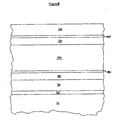
- Figure 3 illustrates an embodiment of the present invention that is especially preferred.
- the layer structure of the coating is like that shown in Figure 1, except that a transparent base layer 20 is positioned between the substrate 10 and the antireflective layer 30.
- This base layer 20 is provided to minimize problems associated with corroded substrates.
- certain transparent base layers 20 have been found to significantly reduce the formation of haze that has otherwise been observed when moisture-corroded glass is used with a temperable low-emissivity coating.
- the transparent base layer 20 can be advantageously formed of silicon dioxide or another amorphous or substantially amorphous film.
- the transparent base layer is formed of substantially amorphous film having an index of refraction that is equal to, or substantially the same as, that of the substrate 10 to which it is applied.
- the base layer 20 can be incorporated on the substrate at essentially any thickness without substantially changing the visible transmission, reflection, or color of the coated substrate.
- the transparent base layer 20 has no strict maximum thickness.
- the transparent base layer 20 is a sputtered silicon dioxide film.
- the base layer 20 is formed of sputtered silicon dioxide, due to the relatively slow sputter rate of silicon dioxide.
- the base layer 20 is formed of sputtered silicon dioxide (since sputtered silicon dioxide tends not to have high stress), some advantage in the way of low stress may be gained by minimizing thickness. Good results are expected for transparent base layers 20 having a thickness of less than 100 angstroms, and even for those having a thickness of less than about 90 angstroms (e.g., about 70 angstroms). Base layers 20 of silicon dioxide, for example, are expected to give good results at these thicknesses.
- the transparent base layer 20 is a sputtered film.
- Sputtered films have exceptional smoothness and thickness uniformity. Both of these qualities are desirable for avoiding haze in heat-treatable silver-based coatings.
- the low surface roughness of a sputtered base layer promotes good thickness uniformity in overlying films. Thickness uniformity is particularly desirable for protective layers 80, 180 if haze is to be minimized.
- Sputtered silicon dioxide base layers are particularly preferred as they tend to have a very desirable amorphous structure.
- the transparent base layer 20 preferably has a minimum thickness of at least about 50 angstroms. A thickness of this magnitude is preferred to significantly reduce problems (e.g., haze formation during tempering) associated with substrate defects (e.g., moisture corrosion).
- the transparent base layer 20 may have a thickness of between about 50 angstroms and about 90 angstroms.
- the base layer 20 is formed directly upon the substrate 10.
- This embodiment provides a low-emissivity coating with a combination of at least one protective niobium-titanium layer 80 and the described transparent base layer 20.
- Low-emissivity coatings with this combination of features are expected to exhibit very little noticeable color shift and minimal haze formation during tempering or other heat treatment (even when subjected to temperatures on the order of about 700 degrees C.).
- these coatings are expected to be particularly well suited for use on substrates that are to be tempered or otherwise heat treated. Coatings of this nature are expected to have desirable scratch resistance as well.
- Figure 4 depicts another preferred embodiment of the invention.
- the illustrated embodiment involves a low-emissivity film stack with two infrared-reflective layers 50, 150.
- an antireflective inner layer 30 is formed upon the substrate.
- this inner layer 30 has an overall thickness of between about 100 ⁇ and about 400 ⁇ , and more preferably between about 100 ⁇ and about 275 ⁇ .
- the inner layer 30 in the present embodiment may include one or more transparent dielectric films.
- this layer 30 may advantageously comprise a metal nitride (e.g., silicon nitride) and/or a metal oxide, such as oxides of zinc, tin, indium, bismuth, titanium, hafnium, zirconium, and alloys and mixtures thereof. Skilled artisans would be able to select other materials that could be used for the antireflective inner layer 30 in this embodiment.
- a metal nitride e.g., silicon nitride
- a metal oxide such as oxides of zinc, tin, indium, bismuth, titanium, hafnium, zirconium, and alloys and mixtures thereof.
- the inner layer 30 in the embodiment of Figure 4 is depicted as being a single film. However, this layer 30 can be replaced with a plurality of separate films, if so desired. For example, this layer 30 may include two separate films, optionally formed of different transparent dielectric materials. If the inner layer 30 in this embodiment consists of a single film, then such film is preferably formed of zinc oxide. For example, this layer 30 may be single film of zinc oxide applied at a thickness of about 230 ⁇ . Whether the inner layer 30 in this embodiment consists of one film or multiple films, it may be optimal to limit each individual film to a physical thickness of less than about 250 ⁇ , or to an optical thickness of no more than about 450 ⁇ , for reasons discussed below.
- the composition of the antireflective inner layer 30 in the embodiment of Figure 4 can be varied as desired. However, it is generally preferred that at least a thin film of zinc oxide be applied as the outermost portion (i.e., the portion farthest away from the substrate) of this layer 30. This is believed to enhance the quality of the film stack, at least if the overlying infrared-reflective film 50 is formed of silver, as zinc oxide is thought to provide a good foundation for the nucleation of silver. Thus, it is preferable to either form the whole of the antireflective inner layer 30 of zinc oxide or to replace this layer 30 with two or more films (not shown), wherein the outermost film is zinc oxide.
- the inner layer 30 in the embodiment of Figure 4 will be replaced with two or more films (not shown) in some cases.
- a variety of film stacks are known to be suitable for use as the antireflective inner region of a "double" type low-emissivity coating.
- the first film i.e., the film nearest the substrate
- the second film is preferably an oxide of zinc alone, at least if the overlying infrared-reflective film 50 is formed of silver.
- One suitable embodiment of this nature involves a first film having a thickness of between about 60 angstroms and about 100 angstroms, perhaps optimally about 90 angstroms, and a second film having a thickness of between about 35 angstroms and about 62 angstroms, perhaps optimally about 40 angstroms.
- the second layer 50 illustrated in Figure 4 is an infrared-reflective film.
- the infrared-reflective materials described above with reference to Figure 1 can also be used for the infrared-reflective layers 50,150 in the embodiment of Figure 4. In most cases, it will be preferable to employ silver or silver-containing layers 50, 150.
- the first infrared-reflective layer 50 comprises silver at a thickness of between about 50 ⁇ and about 150 ⁇ , more preferably between about 58 ⁇ and about 90 ⁇ , and perhaps optimally about 80 ⁇ .
- a protective niobium-titanium layer 80 can be provided advantageously over the first infrared-reflective layer 50.
- the niobium-titanium layers 80, 180 illustrated in Figure 4 are of the nature described above.
- the first niobium-titanium layer 80 is preferably applied directly upon the first infrared-reflective layer 50.
- the thickness of the first niobium-titanium layer 80 is preferably between about 7-30 ⁇ , more preferably between about 15-22 ⁇ , and perhaps optimally about 20 ⁇ .
- an intermediate film region 190 is positioned outwardly from (i.e., further from the substrate than) the first infrared-reflective layer 50 (e.g., upon the protective layer 80, if present).
- this intermediate film region 190 consists of a single layer of any desired transparent dielectric material.
- a single transparent dielectric film e.g., zinc oxide having a thickness of about 400-1200 ⁇ can be used.
- the intermediate film region 190 includes at least one metal oxide film and at least one metal nitride film.
- the present niobium-titanium layer 80 may be particularly advantageous in such embodiments.
- the intermediate film region 190 may include a silicon nitride film (or another substantially amorphous film) and a zinc oxide film, with the zinc oxide film being positioned over (i.e., outwardly from) the silicon nitride film.
- a low-emissivity coating having at least two infrared-reflective films wherein the innermost infrared-reflective film is directly followed, moving outwardly, by a contiguous sequence of a protective niobium-titanium layer, a nitride film (e.g., silicon nitride), and a metal oxide film (e.g., zinc oxide). If so desired, one or more additional films can be provided between the metal oxide film and the second infrared-reflective film.
- a protective niobium-titanium layer e.g., silicon nitride
- a metal oxide film e.g., zinc oxide
- a low-emissivity coating having at least two infrared-reflective films wherein the innermost infrared-reflective film is directly followed, moving outwardly, by a contiguous sequence of a protective niobium-titanium layer, a metal oxide layer (e.g., zinc oxide), and a nitride layer (e.g., silicon nitride).
- a protective niobium-titanium layer e.g., zinc oxide
- a nitride layer e.g., silicon nitride
- one or more additional films can optionally be provided between the metal oxide film and the second infrared-reflective film.
- the intermediate film region 190 is preferable to form the intermediate film region 190 of a plurality of discrete layers. Forming the intermediate film region 190 of a plurality of discrete layers is desirable to minimize haze formation during tempering. This is discussed in International Application Number PCT/US00/42434, entitled “Haze Resistant Transparent Film Stacks", the entire teachings of which are incorporated herein by reference. In embodiments wherein the intermediate film region 190 comprises a plurality of discrete layers, it is preferable to limit each layer of the intermediate film region to a physical thickness of no more than about 250 ⁇ , more preferably no more than about 225 ⁇ , and perhaps optimally less than 200 ⁇ (e.g., about 180 ⁇ or less). This is desirable for reducing the likelihood that objectionable haze will develop in the film stack during heat treatment.
- the intermediate film region 190 comprises alternating crystalline and substantially amorphous films.
- the intermediate film region 190 in these embodiments preferably comprises at least three films (i.e., at least three antireflective transparent dielectric films), perhaps more preferably at least four films, and perhaps optimally at least five films.
- the crystalline film is an oxide and the substantially amorphous film is a nitride.
- the crystalline film is an oxide of a first metal (e.g., zinc), and the substantially amorphous film is a nitride of a second metal (e.g., silicon), where the first and second metals are different.
- the combination in a heat-treatable low-emissivity coating of niobium-titanium protective film and thin alternating crystalline and amorphous intermediate layers is particularly advantageous.
- the ratio of the total thickness of the intermediate film region to the thickness of layer 30 preferably falls within a certain range. In particular, this ratio preferably ranges between about 4.1/1 and about 6.0/1. Thus, the layer 30 preferably is between about 1/4 th and about 1/6 th as thick as the intermediate film region 190. In the present embodiments, the thickness of layer 30 preferably is less than about 230 ⁇ , perhaps more preferably less than about 200 ⁇ (and even less than about 160 ⁇ in some cases), with the thickness of the intermediate film region 190 varying accordingly based on the preferred ratios above. These preferred ratios and thicknesses are particularly desirable when provided in a low-emissivity coating having niobium-titanium protective film in combination with thin alternating intermediate layers of crystalline and substantially amorphous materials.
- Part of the problem in producing low-emissivity coatings is obtaining a coating that provides high visible transmission, high infrared-reflection, and pleasing color.
- the embodiments described in the preceding paragraph provide unique solutions to these problems.
- a related part of this problem involves maintaining these properties, while simultaneously avoiding haze formation and minimizing color change, if the coating is tempered or otherwise heat treated.
- the embodiments described herein comprising the niobium-titanium protective film, optionally in combination with the intermediate film region comprising a plurality of discrete intermediate film layers (perhaps optimally comprising alternating intermediate layers of crystalline and substantially amorphous materials) and/or with the thin transparent base layer, are exceptional solutions to these problems.
- the intermediate film region 190 can advantageously include at least one substantially amorphous layer.
- Materials of this nature are advantageous in that they tend not to experience substantial crystal growth when tempered or otherwise heat treated.
- the intermediate film region 190 tends not to develop objectionable haze during heat treatment.
- Amorphous layers also tend to prevent material migration. For instance, if pinholes or the like develop in adj acent crystalline layers, such pinholes, etc., tend not to propagate through adj acent amorphous layers.
- One preferred embodiment includes an intermediate film region comprising at least one silicon nitride layer.
- this silicon nitride can be broken up into two or more discrete silicon nitride films, separated from one another by film of a material other than silicon nitride (preferably a crystalline material, e.g., a crystalline metal oxide, such as ZnO).
- a material other than silicon nitride preferably a crystalline material, e.g., a crystalline metal oxide, such as ZnO.
- silicon nitride has substantial stress that becomes more problematic as the thickness of the silicon nitride is increased.
- Certain embodiments provide an intermediate film region 190 that comprises one or more silicon nitride films each having an individual thickness of less than about 200 angstroms, perhaps more preferably less than about 175 angstroms, and perhaps optimally less than about 160 angstroms.
- the other intermediate film layers are desirably crystalline oxide layers each having a thickness of no more than about 250 angstroms, more preferably no more than about 225 angstroms, and perhaps optimally less than 200 angstroms (e.g., about 180 angstroms or less).
- the intermediate film region 190 and the outer film region 130 each comprises at least one amorphous layer.
- the intermediate film region 190 includes a silicon nitride film positioned between two zinc oxide films.
- one embodiment provides an intermediate film region 190 comprising, moving outwardly: (1) zinc oxide at a thickness of about 150-250 ⁇ , perhaps optimally about 220 ⁇ ; (2) silicon nitride at a thickness of about 40-120 ⁇ , perhaps optimally about 80-100 ⁇ ; and (3) zinc oxide at a thickness of about 150-250 ⁇ , perhaps optimally about 210 ⁇ . It is believed to be even more preferable to form the intermediate film region 190 of at least five separate layers, as will now be discussed.
- Figure 5 illustrates an embodiment wherein the intermediate film region 190 includes five separate layers.
- the intermediate film region 190 in this embodiment includes a first layer 192, a second layer 193, a third layer 194, a fourth layer 195, and a fifth layer 196.
- these layers 192-196 are provided in the form of alternating zinc oxide and silicon nitride films (e.g., three zinc oxide films 192, 194, 196 and two silicon nitride films 193, 195). Intermediate films of this nature are particularly preferred.
- the intermediate film region 190 may be formed of an odd number of intermediate layers such that the bottom and top layers of this region 190 comprise the same material.
- the first 192 and fifth 196 intermediate films in the embodiment of Figure 5 can both be formed of the same material (e.g., zinc oxide).
- each layer in the intermediate region 190 may advantageously have a different microstructure than each layer contiguous thereto (e.g., amorphous versus crystalline). For example, it may be particularly advantageous to form contiguous layers in the intermediate film region 190 of different materials.
- the intermediate film region 190 comprises the following films: (1) a first layer 192 of zinc oxide at a thickness of about 50-200 ⁇ , perhaps optimally about 105 ⁇ ; (2) a second layer 193 of silicon nitride at a thickness of about 50-200 ⁇ , perhaps optimally about 140 ⁇ ; (3) a third layer 194 of zinc oxide at a thickness of about 50-300 ⁇ , perhaps optimally about 200 ⁇ ; (4) a fourth layer 195 of silicon nitride at a thickness of about 50-200 ⁇ , perhaps optimally about 140 ⁇ ; and (5) a fifth layer 196 of zinc oxide at a thickness of about 50-200 ⁇ , perhaps optimally about 80 ⁇ .
- any one or more of the zinc oxide layers can be formed of an alloy or mixture comprising zinc oxide, such as a mixture of zinc oxide and bismuth oxide, tin oxide, or indium oxide.
- the fifth layer 196 in this embodiment may include a first oxide film with a thickness of about 20 ⁇ , such as an oxide of zinc alloy, and a second film of an oxide of zinc alone at about 60 ⁇ .
- a preferred embodiment of the invention provides a low-emissivity coating that includes at least one protective niobium-titanium layer and an intermediate film region 190 comprising at least three, and preferably at least five, discrete transparent dielectric layers (optimally limited in thickness and comprising alternating crystalline and substantially amorphous layers, as described above).
- Low-emissivity coatings with this combination of features should perform exceptionally well under "adhesion failure with moisture testing", such as that described in the above-noted International Application. Such coatings should also have desirable scratch resistance and should exhibit very little noticeable color shift and haze formation during tempering or other heat treatment.
- a titanium nitride film can be incorporated into the outer film region 90, 130 of the low-emissivity coating.
- one particularly preferred low-emissivity coating includes at least one protective niobium-titanium layer, an intermediate film region comprising discrete multiple transparent dielectric films (optimally limited in thickness and comprising alternating crystalline and substantially amorphous layers, as described above), and an outer titanium nitride film (i.e., a titanium nitride film as the outermost layer, or elsewhere in the outer film region 90, 130).
- at least one chemically-durable outer film can be incorporated into embodiments like that described in the preceding paragraph.
- another particularly preferred low-emissivity coating includes at least one protective niobium-titanium layer, an intermediate film region comprising discrete multiple transparent dielectric films (optimally limited in thickness and comprising alternating crystalline and substantially amorphous layers, as described above), and at least one chemically-durable outer film (e.g., Si 3 N 4 ).
- an outer titanium nitride film and a chemically-durable outer film there can be provided.
- an especially preferred low-emissivity coating includes at least one protective niobium-titanium layer, an intermediate film region comprising discrete multiple transparent dielectric films (optimally limited in thickness and comprising alternating crystalline and substantially amorphous layers, as described above), an outer titanium nitride film, and a chemically-durable outer film (e.g., a silicon nitride film as the outermost layer, or elsewhere in the outer film region 90,130).
- a protective niobium-titanium layer an intermediate film region comprising discrete multiple transparent dielectric films (optimally limited in thickness and comprising alternating crystalline and substantially amorphous layers, as described above), an outer titanium nitride film, and a chemically-durable outer film (e.g., a silicon nitride film as the outermost layer, or elsewhere in the outer film region 90,130).
- Figures 4-9 depict "double" type low-emissivity coatings.
- a second infrared-reflective film 150 is provided in each of these embodiments.
- the materials useful in forming the first infrared-reflective film 50 are also useful in the forming second infrared-reflective film 150.
- both infrared-reflective films 50, 150 will be formed of the same material, although this is not a requirement.
- both films 50, 150 are silver or silver-containing films, with the second, outermost film 150 being somewhat thicker than the first, innermost film 50.
- a preferred embodiment provides a first infrared-reflective layer 50 of silver at a thickness of between about 50 ⁇ and about 150 ⁇ , more preferably between about 58 ⁇ and about 90 ⁇ , perhaps optimally about 80 ⁇ , and a second infrared-reflective layer 150 of silver at a thickness of between about 90 ⁇ and about 180 ⁇ , more preferably between about 96 ⁇ and 155 ⁇ , perhaps optimally at about 130 ⁇ .
- a protective niobium-titanium layer 180 can be provided advantageously over the second infrared-reflective film 150.
- This niobium-titanium layer 180 is of the nature described above.
- this layer 180 is preferably formed directly upon the underlying infrared-reflective film 150.
- the thickness of this niobium-titanium layer 180 is preferably between about 7-30 ⁇ , more preferably between about 15-22 ⁇ , and perhaps optimally about 20 ⁇ .
- both protective layers 80, 180 are niobium-titanium films each deposited at a thickness of about 15-22 ⁇ .
- An additional protective layer can be positioned directly beneath the second infrared-reflective layer 150, if so desired.
- one of the protective layers 80, 180 can be omitted entirely, if so desired.
- an outer film region 130 is positioned outwardly from the second infrared-reflective film 150 (e.g., directly upon the second protective layer 180, if present).
- the exact nature of the outer film region 130 can be varied as desired.
- the outer film region 130 consists of a single transparent dielectric film.
- metal nitrides e.g., silicon nitride
- metal oxides e.g., oxides of zinc, tin, indium, bismuth, titanium, hafnium, zirconium, and alloys and mixtures thereof
- the outer film region 130 is a single film (e.g., silicon nitride) having a thickness of between about 100 ⁇ and about 400 ⁇ , more preferably between about 100 ⁇ and about 300 ⁇ , and perhaps optimally about 280 ⁇ . Those skilled in the art would be able to readily select other materials suitable for use as the outer film region 130.
- each transparent dielectric film (including films in the layer 30, intermediate film region 190, and outer film region 130) has a thickness of less than 200 angstroms.
- Figures 6 and 7 illustrate embodiments wherein the outer film region 130 is formed of a plurality of separate layers.
- the embodiment of Figure 6 has an outer film region 130 comprising two separate layers.
- a first outer layer 132 is deposited directly upon the second protective layer 180.
- the first outer layer 132 can be formed of any desired transparent dielectric material.
- this layer 132 can be advantageously formed of zinc oxide.
- the thickness of the first outer layer 132 is preferably between about 125 ⁇ and about 275 ⁇ , and more preferably between about 150 ⁇ and about 250 ⁇ .
- a second outer layer 134 is deposited directly upon the first outer layer 132.
- this layer 134 can be formed of any desired transparent dielectric material, it is preferably formed of a chemically-durable material, such as silicon nitride.
- the thickness of the second outer layer 134 is preferably between about 25 ⁇ and about 300 ⁇ , and more preferably between about 50 ⁇ and about 125 ⁇ .
- the first outer layer 132 is formed of zinc oxide at a thickness of about 175 ⁇ and the second outer layer 134 is formed of silicon nitride at a thickness of about 75 ⁇ .
- the outer film region 130 comprises two or more films, including at least one titanium nitride film and at least one chemically-durable film (e.g., silicon nitride), with the chemically-durable film preferably, though not necessarily, being positioned outwardly from the titanium nitride film.
- at least one titanium nitride film and at least one chemically-durable film (e.g., silicon nitride), with the chemically-durable film preferably, though not necessarily, being positioned outwardly from the titanium nitride film.
- chemically-durable film e.g., silicon nitride
- Figure 7 illustrates a preferred embodiment wherein the outer film region 130 comprises at least four separate layers. These layers 131, 133, 135, 137 can be formed of any desired transparent dielectric materials.
- a film layer 131 formed of an alloy or mixture of zinc oxide, such as an alloy or mixture of zinc oxide and bismuth oxide, tin oxide, or indium oxide.
- This film layer 131 is preferably deposited at a thickness of between about 50 ⁇ and about 200 ⁇ , more preferably between about 80 ⁇ and about 115 ⁇ , and perhaps optimally about 100 ⁇ .
- first 133 and second 137 chemically-durable layers e.g., silicon nitride
- first 133 and second 137 chemically-durable layers e.g., silicon nitride
- the innermost 133 of these silicon nitride layers preferably has a thickness on the order of about 22-55 ⁇ , perhaps optimally about 30 ⁇ .
- the titanium nitride layer 135 preferably has a thickness on the order of about 4-41 ⁇ , perhaps optimally about 10 ⁇ .
- the outermost silicon nitride layer 137 preferably has a thickness of about 75-179 ⁇ , perhaps optimally about 110 ⁇ .
- certain preferred embodiments of the invention provide a low-emissivity coating having at least one infrared-reflective layer, wherein there is found a contiguous sequence of, moving outwardly, a zinc oxide film, an a silver or silver-containing film, and a niobium-titanium layer.
- the silver or silver-containing film in this contiguous sequence is positioned directly over the zinc oxide film and directly beneath the niobium-titanium layer.
- one or more additional films e.g., silicon dioxide may be provided inwardly from the zinc oxide film in this sequence.
- a transparent dielectric film is preferably positioned over the niobium-titanium layer in this sequence. It is noted that the silver or silver-containing film in this sequence may be the only infrared-reflective film in the coating, or it may be one of two or more infrared-reflective films in the coating.
- This embodiment involves a "double" type low-emissivity coating.
- the layers of this coating will be described in order; moving outwardly (i.e., in a direction away from the substrate).
- a layer of an alloy or mixture of zinc oxide such as an alloy or mixture of zinc oxide and bismuth oxide, tin oxide, or indium oxide, is formed directly upon the base layer.
- This oxide layer preferably has a thickness of between about 250 ⁇ and about 350 ⁇ , perhaps optimally about 300 ⁇ .
- a layer of pure zinc oxide is preferably between about 70 ⁇ and about 100 ⁇ , perhaps optimally about 85 ⁇ .
- An infrared-reflective silver layer is formed directly upon this zinc oxide layer.
- This silver layer preferably has a thickness of between about 90 ⁇ and about 110 ⁇ , perhaps optimally about 100 ⁇ .
- a protective niobium-titanium layer is then applied directly upon this silver layer. The majority of this niobium-titanium may be oxidized or nitrided during the deposition of subsequent layers, as described above.
- the niobium-titanium of this layer is preferably deposited at a thickness of between about 20 ⁇ and about 30 ⁇ , perhaps optimally about 25 ⁇ .
- a layer of pure zinc oxide which layer preferably has a thickness of between about 80 ⁇ and about 120 ⁇ , perhaps optimally about 100 ⁇ .
- a layer of an alloy or mixture of zinc oxide such as an alloy or mixture of zinc oxide and bismuth oxide, tin oxide, or indium oxide.
- This oxide layer preferably has a thickness of between about 530 ⁇ and about 620 ⁇ , and more preferably between about 550 ⁇ and about 700 ⁇ .
- a layer of pure zinc oxide which layer preferably has a thickness of between about 65 ⁇ and about 105 ⁇ , perhaps optimally about 85 ⁇ .
- An infrared-reflective silver layer is formed directly upon this zinc oxide layer.
- This silver layer preferably has a thickness of between about 105 ⁇ and about 145 ⁇ , perhaps optimally about 125 ⁇ .
- a protective niobium-titanium layer which may subsequently be oxidized or nitrided, is then applied directly upon this silver layer.
- the niobium-titanium of this layer is preferably deposited at a thickness of between about 20 ⁇ and about 30 ⁇ , perhaps optimally about 20 ⁇ .
- a layer of pure zinc oxide which layer preferably has a thickness of between about 110 ⁇ and about 130 ⁇ , perhaps optimally about 120 ⁇ .
- a layer of an alloy or mixture of zinc oxide such as an alloy or mixture of zinc oxide and bismuth oxide, tin oxide, or indium oxide.
- This oxide layer preferably has a thickness of between about 130 ⁇ and about 170 ⁇ , perhaps optimally about 150 ⁇ .
- a layer of silicon nitride which preferably forms the outermost layer of the film stack.
- this silicon nitride layer has a thickness of between about 20 ⁇ and about 50 ⁇ , and more preferably between about 30 ⁇ and about 40 ⁇ .
- This embodiment also involves a "double" type low-emissivity coating.
- the layers of this coating will be described in order, moving outwardly.
- a transparent base layer of silicon dioxide Directly upon the substrate, there is formed a transparent base layer of silicon dioxide.
- the base layer preferably has a thickness of between about 70 ⁇ and about 90 ⁇ , perhaps optimally about 80 ⁇ .
- a layer of zinc oxide Directly upon the silicon dioxide base layer is applied a layer of zinc oxide.
- the thickness of this zinc oxide layer is preferably between about 215 ⁇ and about 245 ⁇ , perhaps optimally about 230 ⁇ .
- An infrared-reflective silver layer is applied directly upon this zinc oxide layer.
- This silver layer preferably has a thickness of between about 70 ⁇ and about 90 ⁇ , perhaps optimally about 80 ⁇ .
- a protective niobium-titanium layer is then applied directly upon this silver layer.
- This niobium-titanium layer is preferably deposited at a thickness of between about 18 ⁇ and about 22 ⁇ , perhaps optimally about 20 ⁇ .
- a layer of zinc oxide is then applied directly upon this niobium-titanium layer.
- This zinc oxide layer is preferably deposited at thickness of between about 95 ⁇ and about 115 ⁇ , perhaps optimally about 105 ⁇ .
- a silicon nitride layer is then applied directly upon this zinc oxide layer. This silicon nitride layer preferably has a thickness of between about 120 ⁇ and about 160 ⁇ , perhaps optimally about 140 ⁇ .
- this silicon nitride layer Directly upon this silicon nitride layer is applied a layer of zinc oxide at a thickness of between about 180 ⁇ and about 220 ⁇ , perhaps optimally about 200 ⁇ . A silicon nitride layer is then applied directly upon this zinc oxide layer. This silicon nitride layer preferably has a thickness of between about 120 ⁇ and about 160 ⁇ , perhaps optimally about 140 ⁇ . Directly upon this silicon nitride layer is applied zinc oxide at a thickness of between about 65 ⁇ and about 95 ⁇ , perhaps optimally about 80 ⁇ . An infrared-reflective silver layer is formed directly upon this zinc oxide. This silver layer preferably has a thickness of between about 110 ⁇ and about 150 ⁇ , perhaps optimally about 130 ⁇ . A protective niobium-titanium layer is applied directly upon this silver layer.
- This niobium-titanium layer is preferably deposited at a thickness of between about 18 ⁇ and about 22 ⁇ , perhaps optimally about 20 ⁇ .
- a layer of zinc oxide is then applied directly upon this niobium-titanium layer.
- This zinc oxide layer preferably has a thickness of between about 90 ⁇ and about 110 ⁇ , perhaps optimally about 100 ⁇ .
- a silicon nitride layer is then deposited directly upon this zinc oxide layer.
- This silicon nitride layer preferably has a thickness of between about 20 ⁇ and about 40 ⁇ , perhaps optimally about 30 ⁇ .
- a layer of titanium nitride is then formed directly upon this silicon nitride layer.
- This titanium nitride layer preferably has a thickness of between about 5 ⁇ and about 15 ⁇ , perhaps optimally about 10 ⁇ .
- a silicon nitride film is applied.
- This silicon nitride film preferably has a thickness of between about 85 ⁇ and about 135 ⁇ , perhaps optimally about 110 ⁇ .
- This silicon nitride film is the outermost layer of the film stack.
- a layer of titanium oxide e.g., titanium dioxide, which may be substoichiometric TiO x , where x is between 1 and 2 is applied directly upon the substrate.
- This titanium oxide layer preferably has a thickness of between about 115 ⁇ and about 145 ⁇ , perhaps optimally about 130 ⁇ .
- a layer of pure zinc oxide is applied directly upon this titanium oxide layer.
- the thickness of this zinc oxide layer is preferably between about 40 ⁇ and about 60 ⁇ , perhaps optimally about 50 ⁇ .
- An infrared-reflective silver layer is formed directly upon this zinc oxide layer.
- This silver layer preferably has a thickness of between about 80 ⁇ and about 100 ⁇ , perhaps optimally about 90 ⁇ .
- a protective niobium-titanium layer is formed directly upon this silver layer.
- This protective niobium-titanium layer which may subsequently be oxidized or nitrided, is preferably deposited at a thickness of between about 20 ⁇ and about 30 ⁇ , perhaps optimally about 25 ⁇ .
- a layer of silicon nitride which layer preferably has a thickness of between about 400 ⁇ and about 700 ⁇ , perhaps optimally about 500 ⁇ .
- Directly upon this silicon nitride layer is applied a layer of pure zinc oxide.
- This zinc oxide layer preferably has a thickness of between about 30 ⁇ and about 50 ⁇ , perhaps optimally about 40 ⁇ .
- a layer of infrared-reflective silver layer is formed directly upon this silver layer.
- This silver layer preferably has a thickness of between about 80 ⁇ and about 130 ⁇ , and more preferably between about 100 ⁇ and about 110 ⁇ .
- a protective niobium-titanium layer is formed directly upon this silver layer.
- This protective niobium-titanium layer which may subsequently be oxidized or nitrided, is preferably deposited at a thickness of between about 20 ⁇ and about 30 ⁇ , perhaps optimally about 25 ⁇
- a layer of silicon nitride which preferably forms the outermost layer of the film stack.
- the preferred thickness range for this silicon nitride layer is between about 250 ⁇ and about 310 ⁇ , perhaps optimally about 280 ⁇ .
- Figure 8 illustrates a "double" type low-emissivity coating that is particularly preferred.
- the layer structure of the coating can be like any of those described herein with reference to Figures 4-7, with the provision of a transparent base layer 20 between the substrate 10 and the antireflective layer 30.
- the transparent base layer 20 is of the nature described above with reference to Figure 3.
- this base layer 20 can be provided to minimize problems (e.g., haze formation during tempering) associated with substrate defects (e.g., moisture corrosion).
- low-emissivity coatings that include at least one protective niobium-titanium layer and a transparent base layer 20 should exhibit very little noticeable color shift and very little haze formation during tempering or other heat treatment (even when subjected to temperatures on the order of about 700 degrees C.).
- coatings with this combination of features should be particularly well suited for use on substrates that are to be tempered or otherwise heat treated. Coatings of this nature should have desirable scratch resistance as well.
- Low-emissivity coatings with this unique combination of features should perform exceptionally well under "adhesion failure with moisture testing", such as that described in the above-noted International Application. They should also exhibit very little noticeable color shift and minimal haze formation during tempering or other heat treatment. Further, these coatings should have desirable scratch resistance. Thus, coatings with this combination of features are especially preferred.
- one desirable low-emissivity coating includes at least one protective niobium-titanium layer, an intermediate film region 190 comprising discrete multiple transparent dielectric layers (perhaps optimally limited in thickness and comprising alternating crystalline and substantially amorphous layers, as described above), a transparent base layer 20, and a titanium nitride outer film (e.g., a titanium nitride film as the outermost layer, or elsewhere in the outer film region 90, 130).
- at least one chemically-durable outer film can be incorporated into a coating of the nature described in the preceding paragraph.
- the chemically-durable film or films may be formed of silicon nitride.
- another desirable low-emissivity coating includes at least one protective niobium-titanium layer, an intermediate film region 190 comprising discrete multiple transparent dielectric layers (perhaps optimally limited in thickness and comprising alternating crystalline and substantially amorphous layers, as described above), a transparent base layer 20, and at least one chemically-durable outer film (e.g., a silicon nitride film as the outermost layer, or elsewhere in the outer film region 90, 130).
- an outer titanium nitride film and a chemically-durable outer film e.g., silicon nitride
- a particularly desirable low-emissivity coating includes at least one protective niobium-titanium layer, an intermediate film region 190 comprising discrete multiple transparent dielectric layers, a transparent base layer 20, an outer titanium nitride film, and a chemically-durable outer film.
- Figures 4-9 depict "double" type low-emissivity coatings, which include two infrared-reflective films 50, 150.
- a protective niobium-titanium layer is shown over each of the infrared-reflective films 50, 150. While embodiments of this nature are expected to be particularly advantageous, the invention provides a number of alternate embodiments.
- a protective niobium-titanium layer is provided over only one of the infrared-reflective films 50, 150. In some cases, this may involve a coating wherein only the first infrared-reflective film 50 is provided with an overlying niobium-titanium layer 80.
- the second infrared-reflective film 150 can be provided with an overlying protective film 180 of another material (e.g., titanium, niobium, nickel, chromium, nichrome, etc.), or the second protective layer 180 can be omitted entirely. In other cases, this may involve a coating wherein only the second infrared-reflective film 150 is provided with an overlying niobium-titanium layer 180.
- the inner infrared-reflective layer 50 can be provided with an overlying protective layer 80 of another material, or the first protective layer 80 can be omitted entirely.
- each of the infrared-reflective films 50, 150 in a "double" type low-emissivity coating is sandwiched between protective niobium-titanium layers.
- the niobium-titanium layer beneath each infrared-reflective film may be several angstroms thinner than the niobium-titanium layer over such infrared-reflective film (e.g., to prevent undue reduction in transmissivity).
- niobium-titanium layers may be advantageous not to position niobium-titanium layers directly beneath infrared-reflective films, at least if silver is used in the infrared-reflective films, since a directly underlying zinc oxide film tends to optimize silver growth.
- sandwiching infrared-reflective films, even those formed of silver, directly between niobium-titanium layers may provide a desirable level of protection for the infrared-reflective films. Thus, embodiments of this nature may be desirable.
- a "double" type low-emissivity coating wherein only one of the infrared-reflective films is sandwiched between two niobium-titanium layers. In some cases, this may involve a coating wherein only the first infrared-reflective film 50 is sandwiched between two protective niobium-titanium layers. In these cases, the second infrared-reflective film 150 may have only an overlying niobium-titanium protective layer 180 (or only an overlying protective layer 180 of another material), only an underlying niobium-titanium protective layer (or only an underlying protective layer of another material), or no protective layer whatsoever.
- this may involve a coating wherein only the second infrared-reflective film 150 is sandwiched between protective niobium-titanium layers.
- the first infrared-reflective film 50 may have only an overlying niobium-titanium protective layer 80 (or only an overlying protective layer 80 of another material), only an underlying niobium-titanium protective layer (or only an underlying protective layer of another material), or no protective layer whatsoever.
- a protective niobium-titanium layer can be positioned beneath, but not above, each infrared-reflective film in a low-emissivity coating.
- a low-emissivity coating having at least two infrared-reflective films is provided with a single protective niobium-titanium layer. This niobium-titanium layer may be positioned over, or beneath, any one of the infrared-reflective films in the coating.
- a low-emissivity coating that includes one or more infrared-reflective films and at least one niobium-titanium layer that is contiguous to an infrared-reflective film of the coating.
- film stack portions e.g., inner film regions 30, intermediate film regions 190, outer film regions 90, 130, and particular film sequences
- any one or more of these film stack portions can be incorporated into low-emissivity coatings that include three or more infrared-reflective films.
- a low-emissivity coating having three or more infrared-reflective films wherein a protective niobium-titanium layer is positioned over each infrared-reflective film.
- a low-emissivity coating having three or more infrared-reflective films wherein each infrared-reflective film is sandwiched between two niobium-titanium layers.
- the invention provides a glass pane carrying one of the film stacks detailed above.
- the transmissivity (Illuminant C) of the thus-coated pane is at least about 65%, and in fact is at least about 78%.
- the composition and thickness (as disclosed in the film stacks detailed above) of each infrared-reflective film, each transparent dielectric film, and each protective film is selected, as set forth in examples above, to achieve such transmissivity levels.
Landscapes
- Chemical & Material Sciences (AREA)
- Materials Engineering (AREA)
- Engineering & Computer Science (AREA)
- Chemical Kinetics & Catalysis (AREA)
- General Chemical & Material Sciences (AREA)
- Geochemistry & Mineralogy (AREA)
- Life Sciences & Earth Sciences (AREA)
- Organic Chemistry (AREA)
- Surface Treatment Of Glass (AREA)
- Laminated Bodies (AREA)
- Inorganic Compounds Of Heavy Metals (AREA)
- Chemically Coating (AREA)
- Physical Vapour Deposition (AREA)
- Non-Silver Salt Photosensitive Materials And Non-Silver Salt Photography (AREA)
Claims (28)
- Substrat portant un revêtement de faible émissivité, ledit revêtement de faible émissivité comprenant, en allant vers l'extérieur du substrat :a) une première couche mince comprenant un matériau diélectrique transparent,b) une seconde couche mince comprenant un matériau réfléchissant les infrarouges,c) une troisième couche mince protectrice comprenant du niobium et du titane ; etd) une quatrième couche mince comprenant un matériau diélectrique transparent.
- Substrat selon la revendication 1, dans lequel la couche mince protectrice comprend un plus fort pourcentage de titane que de niobium, de sorte que la couche mince protectrice confère une résistance à l'abrasion dans le revêtement de faible émissivité.
- Substrat selon la revendication 2, dans lequel la couche mince protectrice comprend un pourcentage majeur de titane et un pourcentage mineur de niobium.
- Substrat selon la revendication 3, dans lequel la couche mince protectrice comprend entre 50 % et environ 95 % de titane, et moins de 50 % mais plus d'environ 5 % de niobium.
- Substrat selon la revendication 4, dans lequel la couche mince protectrice comprend environ 55 % de titane et environ 45 % de niobium.
- Substrat selon la revendication 1, dans lequel la couche mince protectrice comprend un plus fort pourcentage de niobium que de titane, de sorte que la couche mince protectrice confère dans le revêtement de faible émissivité une résistance au changement de couleur au cours de l'exposition à des températures élevées de l'ordre d'environ 700 °C.
- Substrat selon la revendication 6, dans lequel la couche mince protectrice comprend un pourcentage majeur de niobium et un pourcentage mineur de titane.
- Substrat selon la revendication 7, dans lequel la couche mince protectrice comprend entre 50 % et environ 95 % de niobium, et moins de 50 % mais plus d'environ 5 % de titane.
- Substrat selon l'une quelconque des revendications précédentes, dans lequel la couche mince protectrice est formée directement sur la seconde couche mince.
- Substrat selon l'une quelconque des revendications précédentes, dans lequel la couche mince protectrice a une épaisseur entre environ 10 angströms et environ 30 angströms.
- Substrat selon l'une quelconque des revendications précédentes, dans lequel la première couche mince a une épaisseur de moins de 230 angströms environ.
- Substrat selon l'une quelconque des revendications précédentes, comprenant en outre :a) une cinquième couche mince comprenant un matériau réfléchissant les infrarouges ; etb) une sixième couche mince comprenant un matériau diélectrique transparent.
- Substrat selon la revendication 12, comprenant en outre une couche mince protectrice positionnée entre les cinquième et sixième couches minces, la couche mince protectrice comprenant du niobium et du titane.
- Substrat selon l'une quelconque des revendications précédentes, comprenant en outre une couche de base transparente positionnée entre le substrat et la première couche mince, la couche de base transparente comprenant de l'oxyde de silicium formé directement sur le substrat
- Substrat selon la revendication 14, dans lequel l'oxyde de silicium est une couche mince déposée par projection.
- Substrat selon la revendication 14 ou la revendication 15, dans lequel la couche de base transparente présente une épaisseur inférieure à 100 angströms.
- Substrat selon l'une quelconque des revendications 1 à 13, dans lequel le substrat est transparent et dans lequel une couche de base transparente d'une matière sensiblement amorphe est formée directement sur le substrat.
- Substrat transparent selon la revendication 17, dans lequel la matière sensiblement amorphe présente un indice de réfraction qui est sensiblement égal à celui du substrat transparent.
- Substrat transparent selon la revendication 17 ou la revendication 18, dans lequel la couche de base transparente présente une épaisseur inférieure à 100 angströms.
- Substrat selon la revendication 1, comprenant en outre une région de couches intermédiaire comprenant des couches alternées de matière sensiblement amorphe et cristalline, dans lequel la région de couches intermédiaire comprend au moins trois couches minces, et une couche comprenant un matériau réfléchissant formée sur la région de couches intermédiaire.
- Substrat selon la revendication 20, dans lequel chacune des couches minces dans la région de couches intermédiaire a une épaisseur inférieure à 200 angströms.
- Substrat selon la revendication 20 ou la revendication 21, dans lequel ladite matière cristalline est un oxyde et ladite matière sensiblement amorphe est un nitrure.
- Substrat selon la revendication 22, dans lequel ledit nitrure est du nitrure de silicium.
- Substrat selon l'une quelconque des revendications 20 à 23, dans lequel la région de couches intermédiaire comprend au moins cinq couches minces.
- Substrat selon la revendication 24, dans lequel la région de couches intermédiaire comprend trois couches minces d'oxyde de zinc et deux couches minces de nitrure de silicium.
- Substrat selon l'une quelconque des revendications 20 à 25, comprenant en outre une couche de base transparente positionnée entre le substrat et la première couche mince, la couche de base transparente comprenant de l'oxyde de silicium formée directement sur le substrat.
- Substrat selon la revendication 26, dans lequel la couche de base transparente présente une épaisseur inférieure à 100 angströms.
- Procédé de production de substrats revêtus, ledit procédé comprenant des étapes consistant à :a) déposer sur un substrat une première couche mince comprenant un matériau diélectrique transparent ;b) déposer sur ladite première couche mince une seconde couche mince comprenant un matériau réfléchissant les infrarouges ;c) déposer sur ladite seconde couche mince une troisième couche mince protectrice comprenant du niobium et du titane ; etd) déposer sur ladite troisième couche mince une quatrième couche mince comprenant un matériau diélectrique transparent.
Priority Applications (1)
| Application Number | Priority Date | Filing Date | Title |
|---|---|---|---|
| EP05077578A EP1630142B1 (fr) | 2002-03-01 | 2003-02-28 | Revêtement à couches minces comportant une couche avec du niobium et du titane |
Applications Claiming Priority (5)
| Application Number | Priority Date | Filing Date | Title |
|---|---|---|---|
| US10/087,662 US6919133B2 (en) | 2002-03-01 | 2002-03-01 | Thin film coating having transparent base layer |
| US87662 | 2002-03-01 | ||
| US123032 | 2002-04-11 | ||
| US10/123,032 US7037589B2 (en) | 2002-03-01 | 2002-04-11 | Thin film coating having niobium-titanium layer |
| PCT/US2003/006134 WO2003074441A1 (fr) | 2002-03-01 | 2003-02-28 | Revetement a film fin comportant une couche de niobium-titane |
Related Child Applications (1)
| Application Number | Title | Priority Date | Filing Date |
|---|---|---|---|
| EP05077578A Division EP1630142B1 (fr) | 2002-03-01 | 2003-02-28 | Revêtement à couches minces comportant une couche avec du niobium et du titane |
Publications (2)
| Publication Number | Publication Date |
|---|---|
| EP1480921A1 EP1480921A1 (fr) | 2004-12-01 |
| EP1480921B1 true EP1480921B1 (fr) | 2006-01-25 |
Family
ID=27791180
Family Applications (4)
| Application Number | Title | Priority Date | Filing Date |
|---|---|---|---|
| EP06076705A Expired - Lifetime EP1748035B1 (fr) | 2002-03-01 | 2003-02-28 | Revêtement à couches minces presentant une couche de base transparente |
| EP03713784A Expired - Lifetime EP1480920B1 (fr) | 2002-03-01 | 2003-02-28 | Revetement a couches minces presentant une couche de base transparente |
| EP03716233A Expired - Lifetime EP1480921B1 (fr) | 2002-03-01 | 2003-02-28 | Revetement a film fin comportant une couche de niobium-titane |
| EP05077578A Expired - Lifetime EP1630142B1 (fr) | 2002-03-01 | 2003-02-28 | Revêtement à couches minces comportant une couche avec du niobium et du titane |
Family Applications Before (2)
| Application Number | Title | Priority Date | Filing Date |
|---|---|---|---|
| EP06076705A Expired - Lifetime EP1748035B1 (fr) | 2002-03-01 | 2003-02-28 | Revêtement à couches minces presentant une couche de base transparente |
| EP03713784A Expired - Lifetime EP1480920B1 (fr) | 2002-03-01 | 2003-02-28 | Revetement a couches minces presentant une couche de base transparente |
Family Applications After (1)
| Application Number | Title | Priority Date | Filing Date |
|---|---|---|---|
| EP05077578A Expired - Lifetime EP1630142B1 (fr) | 2002-03-01 | 2003-02-28 | Revêtement à couches minces comportant une couche avec du niobium et du titane |
Country Status (8)
| Country | Link |
|---|---|
| US (1) | US20060124449A1 (fr) |
| EP (4) | EP1748035B1 (fr) |
| JP (2) | JP3974583B2 (fr) |
| AT (3) | ATE383322T1 (fr) |
| AU (2) | AU2003219948A1 (fr) |
| CA (2) | CA2477844C (fr) |
| DE (2) | DE60309441T2 (fr) |
| WO (2) | WO2003074442A1 (fr) |
Families Citing this family (31)
| Publication number | Priority date | Publication date | Assignee | Title |
|---|---|---|---|---|
| US7138182B2 (en) * | 2002-07-31 | 2006-11-21 | Cardinal Cg Compay | Temperable high shading performance coatings |
| US7494717B2 (en) * | 2003-02-14 | 2009-02-24 | Agc Flat Glass Europe Sa | Glazing panel carrying a coating stack |
| KR100983088B1 (ko) * | 2004-02-25 | 2010-09-20 | 에이지씨 플랫 글래스 노스 아메리카, 인코퍼레이티드 | 열안정화된 아화학량론적 유전체 |
| WO2006067102A2 (fr) * | 2004-12-21 | 2006-06-29 | Glaverbel | Feuille de verre portant un empilage multi-couches |
| DE102005039707B4 (de) | 2005-08-23 | 2009-12-03 | Saint-Gobain Glass Deutschland Gmbh | Thermisch hoch belastbares Low-E-Schichtsystem für transparente Substrate, insbesondere für Glasscheiben |
| FR2898123B1 (fr) | 2006-03-06 | 2008-12-05 | Saint Gobain | Substrat muni d'un empilement a proprietes thermiques |
| FR2898122B1 (fr) | 2006-03-06 | 2008-12-05 | Saint Gobain | Substrat muni d'un empilement a proprietes thermiques |
| ITRM20060181A1 (it) | 2006-03-31 | 2007-10-01 | Pilkington Italia Spa | Lastra di vetro rivestita |
| US7597965B2 (en) * | 2006-09-18 | 2009-10-06 | Guardian Industries Corp. | Coated article with low-E coating having absorbing layer designed to neutralize color at off-axis viewing angles |
| WO2008065962A1 (fr) * | 2006-11-27 | 2008-06-05 | National Institute Of Advanced Industrial Science And Technology | Feuille transparente à la lumière visible et réfléchissant la chaleur |
| EP1980539A1 (fr) * | 2007-03-19 | 2008-10-15 | AGC Flat Glass Europe SA | Vitrage à faible emissivite |
| US7901781B2 (en) | 2007-11-23 | 2011-03-08 | Agc Flat Glass North America, Inc. | Low emissivity coating with low solar heat gain coefficient, enhanced chemical and mechanical properties and method of making the same |
| FR2927897B1 (fr) | 2008-02-27 | 2011-04-01 | Saint Gobain | Vitrage antisolaire presentant un coefficient de transmission lumineuse ameliore. |
| US8703281B2 (en) | 2011-01-11 | 2014-04-22 | Guardian Industries Corp. | Heat treatable coated article with breaker layer |
| EP2492251B1 (fr) | 2011-02-23 | 2017-01-04 | Schott Ag | Substrat doté d'un revêtement anti-réfléchissant et son procédé de fabrication |
| DE102014108058A1 (de) | 2014-06-06 | 2015-12-17 | Schott Ag | Optisches Element mit hoher Kratzbeständigkeit |
| GB201106788D0 (en) * | 2011-04-21 | 2011-06-01 | Pilkington Group Ltd | Heat treatable coated glass pane |
| US20130127202A1 (en) * | 2011-11-23 | 2013-05-23 | Shandon Dee Hart | Strengthened Glass and Glass Laminates Having Asymmetric Impact Resistance |
| WO2014017448A1 (fr) * | 2012-07-24 | 2014-01-30 | 旭硝子株式会社 | Stratifié |
| US9279910B2 (en) * | 2013-03-13 | 2016-03-08 | Intermolecular, Inc. | Color shift of high LSG low emissivity coating after heat treatment |
| US9499899B2 (en) * | 2013-03-13 | 2016-11-22 | Intermolecular, Inc. | Systems, methods, and apparatus for production coatings of low-emissivity glass including a ternary alloy |
| US9790127B2 (en) * | 2013-03-14 | 2017-10-17 | Intermolecular, Inc. | Method to generate high LSG low-emissivity coating with same color after heat treatment |
| US9296650B1 (en) | 2014-10-13 | 2016-03-29 | Intermolecular, Inc. | Low-E panels and methods for forming the same |
| EP3159318A1 (fr) * | 2015-10-20 | 2017-04-26 | Saint-Gobain Glass France | Vitrage résistant au feu et revêtement pour verre résistant au feu |
| US10766808B2 (en) * | 2016-10-18 | 2020-09-08 | Guardian Glass Holding S.P.C. | Coated article with low-E coating having low visible transmission |
| US10830933B2 (en) * | 2018-06-12 | 2020-11-10 | Guardian Glass, LLC | Matrix-embedded metamaterial coating, coated article having matrix-embedded metamaterial coating, and/or method of making the same |
| CN109267026B (zh) * | 2018-11-21 | 2020-08-07 | 西南交通大学 | 一种钛基底着多重及图案化颜色的方法 |
| FR3107703B1 (fr) * | 2020-02-28 | 2023-06-23 | Saint Gobain | Vitrage de controle solaire comprenant une couche de nitrure de titane |
| FR3110160B1 (fr) | 2020-05-12 | 2023-10-27 | Saint Gobain | Matériau bas émissif comprenant une couche épaisse à base d'oxyde de silicium |
| FR3110159A1 (fr) | 2020-05-12 | 2021-11-19 | Saint-Gobain Glass France | Matériau bas émissif comprenant une couche à base de nitrure ou d'oxynitrure de silicium et une couche à base d'oxyde de zinc et d'étain |
| FR3110158B1 (fr) | 2020-05-12 | 2023-10-27 | Saint Gobain | Matériau bas émissif comprenant un revêtement intermédiaire comprenant deux couches comprenant du silicium différentes |
Family Cites Families (77)
| Publication number | Priority date | Publication date | Assignee | Title |
|---|---|---|---|---|
| BE787599A (fr) * | 1971-08-16 | 1973-02-16 | Battelle Memorial Institute | Vitrage filtrant antisolaire et isolant thermique |
| US4166018A (en) | 1974-01-31 | 1979-08-28 | Airco, Inc. | Sputtering process and apparatus |
| GB1507465A (en) * | 1974-06-14 | 1978-04-12 | Pilkington Brothers Ltd | Coating glass |
| FR2276601A1 (fr) * | 1974-06-27 | 1976-01-23 | France Etat | Filtres de bande et application a la fabrication de lunettes de protection |
| US3962488A (en) | 1974-08-09 | 1976-06-08 | Ppg Industries, Inc. | Electrically conductive coating |
| DE2646513C2 (de) * | 1976-10-15 | 1984-10-04 | Bfg Glassgroup, Paris | Verfahren zur Herstellung einer wärmereflektierenden Natron-Kalk-Silikatglasscheibe |
| GB1573154A (en) * | 1977-03-01 | 1980-08-13 | Pilkington Brothers Ltd | Coating glass |
| US4100330A (en) * | 1977-03-28 | 1978-07-11 | Ppg Industries, Inc. | Method for coating glass with silicon and a metal oxide and resulting product |
| US4737252A (en) * | 1981-05-18 | 1988-04-12 | Westinghouse Electric Corp. | Method of coating a metallic article of merchandise with a protective transparent film of abrasion-resistance material |
| JPS5826052A (ja) * | 1981-08-06 | 1983-02-16 | Asahi Glass Co Ltd | アルカリ拡散防止酸化ケイ素膜付ガラス体 |
| NO157212C (no) * | 1982-09-21 | 1988-02-10 | Pilkington Brothers Plc | Fremgangsmaate for fremstilling av belegg med lav emisjonsevne. |
| US4737379A (en) * | 1982-09-24 | 1988-04-12 | Energy Conversion Devices, Inc. | Plasma deposited coatings, and low temperature plasma method of making same |
| US4619729A (en) * | 1984-02-14 | 1986-10-28 | Energy Conversion Devices, Inc. | Microwave method of making semiconductor members |
| US4610771A (en) * | 1984-10-29 | 1986-09-09 | Ppg Industries, Inc. | Sputtered films of metal alloy oxides and method of preparation thereof |
| DE3543178A1 (de) * | 1985-12-06 | 1987-06-11 | Leybold Heraeus Gmbh & Co Kg | Verfahren zum herstellen von scheiben mit hohem transmissionsverhalten im sichtbaren spektralbereich und mit hohem reflexionsverhalten fuer waermestrahlung sowie durch das verfahren hergestellte scheiben |
| DE3750823C5 (de) * | 1986-01-29 | 2006-01-26 | Pilkington Plc, St. Helens | Beschichtetes Glas. |
| US4946712A (en) * | 1986-08-28 | 1990-08-07 | Libbey-Owens-Ford Co. | Glass coating method and resulting article |
| US4847157A (en) * | 1986-08-28 | 1989-07-11 | Libbey-Owens-Ford Co. | Glass coating method and resulting article |
| US4773717A (en) * | 1986-11-03 | 1988-09-27 | Ovonic Synthetic Materials Co. | Transparency having a second surface multilayer decorative coating |
| US4859532A (en) * | 1986-11-27 | 1989-08-22 | Asahi Glass Company Ltd. | Transparent laminated product |
| US4806220A (en) | 1986-12-29 | 1989-02-21 | Ppg Industries, Inc. | Method of making low emissivity film for high temperature processing |
| US4902081A (en) * | 1987-05-22 | 1990-02-20 | Viracon, Inc. | Low emissivity, low shading coefficient low reflectance window |
| US4790922A (en) | 1987-07-13 | 1988-12-13 | Viracon, Inc. | Temperable low emissivity and reflective windows |
| US5201926A (en) * | 1987-08-08 | 1993-04-13 | Leybold Aktiengesellschaft | Method for the production of coated glass with a high transmissivity in the visible spectral range and with a high reflectivity for thermal radiation |
| US5318685A (en) * | 1987-08-18 | 1994-06-07 | Cardinal Ig Company | Method of making metal oxide films having barrier properties |
| JPH01114802A (ja) * | 1987-10-28 | 1989-05-08 | Toshiba Corp | 光干渉膜 |
| US5308706A (en) * | 1988-07-27 | 1994-05-03 | Nippon Sheet Glass Co., Ltd. | Heat reflecting sandwich plate |
| GB8900165D0 (en) * | 1989-01-05 | 1989-03-01 | Glaverbel | Glass coating |
| US5328768A (en) * | 1990-04-03 | 1994-07-12 | Ppg Industries, Inc. | Durable water repellant glass surface |
| JPH05502310A (ja) * | 1990-08-30 | 1993-04-22 | バイラテック・シン・フィルムズ・インコーポレイテッド | 酸化ニオブを含むdc反応性スパッタリングされた光学被覆 |
| FR2666324B1 (fr) * | 1990-09-03 | 1993-04-09 | Saint Gobain Vitrage Int | Couches minces de nitrure de silicium a proprietes ameliorees. |
| US5135808A (en) * | 1990-09-27 | 1992-08-04 | Diamonex, Incorporated | Abrasion wear resistant coated substrate product |
| US5268217A (en) * | 1990-09-27 | 1993-12-07 | Diamonex, Incorporated | Abrasion wear resistant coated substrate product |
| US5637353A (en) * | 1990-09-27 | 1997-06-10 | Monsanto Company | Abrasion wear resistant coated substrate product |
| US5527596A (en) * | 1990-09-27 | 1996-06-18 | Diamonex, Incorporated | Abrasion wear resistant coated substrate product |
| US5190807A (en) * | 1990-10-18 | 1993-03-02 | Diamonex, Incorporated | Abrasion wear resistant polymeric substrate product |
| US5424130A (en) * | 1991-05-13 | 1995-06-13 | Toyota Jidosha Kabushiki Kaisha | Water repellent glass and process for producing the same |
| US5168003A (en) * | 1991-06-24 | 1992-12-01 | Ford Motor Company | Step gradient anti-iridescent coatings |
| JPH0818849B2 (ja) * | 1991-08-29 | 1996-02-28 | 日本板硝子株式会社 | 熱線遮蔽ガラス |
| DE4135701C2 (de) * | 1991-10-30 | 1995-09-28 | Leybold Ag | Scheibe mit hohem Transmissionsverhalten im sichtbaren Spektralbereich und mit hohem Reflexionsverhalten für Wärmestrahlung |
| US6139969A (en) * | 1991-11-29 | 2000-10-31 | Ppg Industries Ohio, Inc. | Reactive sputtering of silicon and transition metal |
| US5302449A (en) * | 1992-03-27 | 1994-04-12 | Cardinal Ig Company | High transmittance, low emissivity coatings for substrates |
| US5296302A (en) * | 1992-03-27 | 1994-03-22 | Cardinal Ig Company | Abrasion-resistant overcoat for coated substrates |
| US5344718A (en) | 1992-04-30 | 1994-09-06 | Guardian Industries Corp. | High performance, durable, low-E glass |
| US5580364A (en) * | 1992-07-11 | 1996-12-03 | Libbey-Owens-Ford Co. | Method of producing a coated glass substrate exhibiting reflected color |
| DE69305936T3 (de) * | 1992-07-11 | 2004-07-22 | Pilkington United Kingdom Ltd., St. Helens | Verfahren zur Herstellung von reflektierenden Schichten auf Glas |
| JP2716330B2 (ja) * | 1992-11-13 | 1998-02-18 | セントラル硝子株式会社 | 低反射ガラスおよびその製法 |
| FR2701475B1 (fr) * | 1993-02-11 | 1995-03-31 | Saint Gobain Vitrage Int | Substrats en verre revêtus d'un empilement de couches minces, application à des vitrages à propriétés de réflexion dans l'infra-rouge et/ou à propriétés dans le domaine du rayonnement solaire. |
| US5337191A (en) * | 1993-04-13 | 1994-08-09 | Photran Corporation | Broad band pass filter including metal layers and dielectric layers of alternating refractive index |
| FR2704545B1 (fr) * | 1993-04-29 | 1995-06-09 | Saint Gobain Vitrage Int | Vitrage muni d'une couche fonctionnelle conductrice et/ou basse-émissive. |
| US5749931A (en) * | 1993-07-08 | 1998-05-12 | Libbey-Owens-Ford Co. | Coatings on glass |
| US5688585A (en) * | 1993-08-05 | 1997-11-18 | Guardian Industries Corp. | Matchable, heat treatable, durable, IR-reflecting sputter-coated glasses and method of making same |
| US5510173A (en) * | 1993-08-20 | 1996-04-23 | Southwall Technologies Inc. | Multiple layer thin films with improved corrosion resistance |
| DE69428253T2 (de) * | 1993-11-12 | 2002-06-27 | Ppg Industries Ohio, Inc. | Haltbare Sputterschicht aus Metalloxid |
| DE69503896T3 (de) * | 1994-05-03 | 2005-10-27 | Cardinal Cg Co., Eden Prairie | Transparenter gegenstand mit siliciumnitrid-schutzschicht |
| US5578103A (en) * | 1994-08-17 | 1996-11-26 | Corning Incorporated | Alkali metal ion migration control |
| ZA956811B (en) * | 1994-09-06 | 1996-05-14 | Boc Group Inc | Dual cylindrical target magnetron with multiple anodes |
| FR2728559B1 (fr) * | 1994-12-23 | 1997-01-31 | Saint Gobain Vitrage | Substrats en verre revetus d'un empilement de couches minces a proprietes de reflexion dans l'infrarouge et/ou dans le domaine du rayonnement solaire |
| FR2730990B1 (fr) * | 1995-02-23 | 1997-04-04 | Saint Gobain Vitrage | Substrat transparent a revetement anti-reflets |
| DE19520843A1 (de) * | 1995-06-08 | 1996-12-12 | Leybold Ag | Scheibe aus durchscheinendem Werkstoff sowie Verfahren zu ihrer Herstellung |
| US6086210A (en) * | 1995-06-29 | 2000-07-11 | Cardinal Ig Company | Bendable mirrors and method of manufacture |
| PT811583E (pt) * | 1995-12-26 | 2002-03-28 | Nippon Sheet Glass Co Ltd | Artigo de vidro revestido com um revestimento corado absorvente de radiacao ultravioleta |
| US5756192A (en) * | 1996-01-16 | 1998-05-26 | Ford Motor Company | Multilayer coating for defrosting glass |
| US5976678A (en) * | 1996-02-27 | 1999-11-02 | Nippon Sheet Glass Co., Ltd. | Colored film-covered glass articles |
| US6316111B1 (en) * | 1996-03-01 | 2001-11-13 | Cardinal Cg Company | Heat-emperable coated glass article |
| GB9606281D0 (en) * | 1996-03-26 | 1996-05-29 | Glaverbel | Coated substrate for a transparent assembly with high selectivity |
| FR2748743B1 (fr) * | 1996-05-14 | 1998-06-19 | Saint Gobain Vitrage | Vitrage a revetement antireflet |
| US6231999B1 (en) | 1996-06-21 | 2001-05-15 | Cardinal Ig Company | Heat temperable transparent coated glass article |
| DE69710678T2 (de) * | 1996-11-18 | 2002-08-01 | Nippon Sheet Glass Co., Ltd. | Wasserabweisende Glasscheibe und Verfahren zu ihrer Herstellung |
| FR2757151B1 (fr) * | 1996-12-12 | 1999-01-08 | Saint Gobain Vitrage | Vitrage comprenant un substrat muni d'un empilement de couches minces pour la protection solaire et/ou l'isolation thermique |
| US6007901A (en) * | 1997-12-04 | 1999-12-28 | Cpfilms, Inc. | Heat reflecting fenestration products with color corrective and corrosion protective layers |
| JP3781888B2 (ja) * | 1998-02-13 | 2006-05-31 | 日産自動車株式会社 | 親水性基材およびその製造方法 |
| FR2781789B1 (fr) * | 1998-08-03 | 2001-08-03 | Saint Gobain Vitrage | Substrat transparent comportant un reseau de fils metalliques et utilisation de ce substrat |
| FR2784985B1 (fr) * | 1998-10-22 | 2001-09-21 | Saint Gobain Vitrage | Substrat transparent muni d'un empilement de couches minces |
| JP2001003166A (ja) * | 1999-04-23 | 2001-01-09 | Nippon Sheet Glass Co Ltd | 基体表面に被膜を被覆する方法およびその方法による基体 |
| JP3477148B2 (ja) | 1999-12-02 | 2003-12-10 | カーディナル・シージー・カンパニー | 耐曇り性透明フィルム積層体 |
| EP1476300B2 (fr) * | 2002-02-11 | 2016-07-13 | PPG Industries Ohio, Inc. | Revêtement contre le soleil |
-
2003
- 2003-02-28 CA CA2477844A patent/CA2477844C/fr not_active Expired - Fee Related
- 2003-02-28 DE DE60309441T patent/DE60309441T2/de not_active Expired - Lifetime
- 2003-02-28 EP EP06076705A patent/EP1748035B1/fr not_active Expired - Lifetime
- 2003-02-28 CA CA2477845A patent/CA2477845C/fr not_active Expired - Fee Related
- 2003-02-28 JP JP2003572915A patent/JP3974583B2/ja not_active Expired - Fee Related
- 2003-02-28 AT AT05077578T patent/ATE383322T1/de not_active IP Right Cessation
- 2003-02-28 WO PCT/US2003/006168 patent/WO2003074442A1/fr active IP Right Grant
- 2003-02-28 DE DE60303368T patent/DE60303368T2/de not_active Expired - Lifetime
- 2003-02-28 EP EP03713784A patent/EP1480920B1/fr not_active Expired - Lifetime
- 2003-02-28 AT AT03713784T patent/ATE344217T1/de not_active IP Right Cessation
- 2003-02-28 EP EP03716233A patent/EP1480921B1/fr not_active Expired - Lifetime
- 2003-02-28 AT AT03716233T patent/ATE316517T1/de not_active IP Right Cessation
- 2003-02-28 AU AU2003219948A patent/AU2003219948A1/en not_active Abandoned
- 2003-02-28 JP JP2003572916A patent/JP4031760B2/ja not_active Expired - Fee Related
- 2003-02-28 EP EP05077578A patent/EP1630142B1/fr not_active Expired - Lifetime
- 2003-02-28 WO PCT/US2003/006134 patent/WO2003074441A1/fr active IP Right Grant
- 2003-02-28 AU AU2003217818A patent/AU2003217818A1/en not_active Abandoned
-
2005
- 2005-12-06 US US11/295,088 patent/US20060124449A1/en not_active Abandoned
Also Published As
| Publication number | Publication date |
|---|---|
| EP1480920B1 (fr) | 2006-11-02 |
| EP1480921A1 (fr) | 2004-12-01 |
| DE60309441D1 (de) | 2006-12-14 |
| CA2477844A1 (fr) | 2003-09-12 |
| JP4031760B2 (ja) | 2008-01-09 |
| AU2003219948A1 (en) | 2003-09-16 |
| CA2477844C (fr) | 2010-10-05 |
| EP1630142A3 (fr) | 2006-04-12 |
| JP3974583B2 (ja) | 2007-09-12 |
| AU2003217818A1 (en) | 2003-09-16 |
| ATE316517T1 (de) | 2006-02-15 |
| EP1748035A1 (fr) | 2007-01-31 |
| CA2477845A1 (fr) | 2003-09-12 |
| DE60303368D1 (de) | 2006-04-13 |
| ATE383322T1 (de) | 2008-01-15 |
| CA2477845C (fr) | 2010-10-12 |
| JP2005526635A (ja) | 2005-09-08 |
| EP1630142A2 (fr) | 2006-03-01 |
| WO2003074442A1 (fr) | 2003-09-12 |
| DE60303368T2 (de) | 2006-10-19 |
| EP1480920A1 (fr) | 2004-12-01 |
| EP1630142B1 (fr) | 2008-01-09 |
| DE60309441T2 (de) | 2007-09-20 |
| WO2003074441A1 (fr) | 2003-09-12 |
| EP1748035B1 (fr) | 2010-10-20 |
| US20060124449A1 (en) | 2006-06-15 |
| JP2005518970A (ja) | 2005-06-30 |
| ATE344217T1 (de) | 2006-11-15 |
Similar Documents
| Publication | Publication Date | Title |
|---|---|---|
| EP1480921B1 (fr) | Revetement a film fin comportant une couche de niobium-titane | |
| US7037589B2 (en) | Thin film coating having niobium-titanium layer | |
| EP0536607B2 (fr) | Revêtements d'aspects métalliques propres au traitement thermique | |
| EP1235757B1 (fr) | Empilements de films transparents resistant au trouble | |
| EP0339274B1 (fr) | Films neutres d'oxydes d'alliages métalliques obtenus par pulvérisation neutre | |
| EP1734019B1 (fr) | Article revêtu avec couche de réflexion IR et procédé de fabrication de cet article | |
| EP0883584B1 (fr) | Article transparent de verre revetu resistant a la trempe a chaud | |
| US10067274B2 (en) | Nickel-aluminum blocker film low-emissivity coatings | |
| CN114430732B (zh) | 具有吸收膜的低e可匹配涂覆制品及相应方法 | |
| CN113614046B (zh) | 具有吸收膜的低e可匹配涂覆制品及相应方法 | |
| EP1754691B1 (fr) | Empilement de couches transparentes resistantes à la formation de voile | |
| WO2024028175A1 (fr) | Vitrage antisolaire à faible émissivité |
Legal Events
| Date | Code | Title | Description |
|---|---|---|---|
| PUAI | Public reference made under article 153(3) epc to a published international application that has entered the european phase |
Free format text: ORIGINAL CODE: 0009012 |
|
| 17P | Request for examination filed |
Effective date: 20040908 |
|
| AK | Designated contracting states |
Kind code of ref document: A1 Designated state(s): AT BE BG CH CY CZ DE DK EE ES FI FR GB GR HU IE IT LI LU MC NL PT SE SI SK TR |
|
| AX | Request for extension of the european patent |
Extension state: AL LT LV MK RO |
|
| GRAP | Despatch of communication of intention to grant a patent |
Free format text: ORIGINAL CODE: EPIDOSNIGR1 |
|
| GRAS | Grant fee paid |
Free format text: ORIGINAL CODE: EPIDOSNIGR3 |
|
| GRAA | (expected) grant |
Free format text: ORIGINAL CODE: 0009210 |
|
| AK | Designated contracting states |
Kind code of ref document: B1 Designated state(s): AT BE BG CH CY CZ DE DK EE ES FI FR GB GR HU IE IT LI LU MC NL PT SE SI SK TR |
|
| PG25 | Lapsed in a contracting state [announced via postgrant information from national office to epo] |
Ref country code: SK Free format text: LAPSE BECAUSE OF FAILURE TO SUBMIT A TRANSLATION OF THE DESCRIPTION OR TO PAY THE FEE WITHIN THE PRESCRIBED TIME-LIMIT Effective date: 20060125 Ref country code: CH Free format text: LAPSE BECAUSE OF FAILURE TO SUBMIT A TRANSLATION OF THE DESCRIPTION OR TO PAY THE FEE WITHIN THE PRESCRIBED TIME-LIMIT Effective date: 20060125 Ref country code: LI Free format text: LAPSE BECAUSE OF FAILURE TO SUBMIT A TRANSLATION OF THE DESCRIPTION OR TO PAY THE FEE WITHIN THE PRESCRIBED TIME-LIMIT Effective date: 20060125 Ref country code: SI Free format text: LAPSE BECAUSE OF FAILURE TO SUBMIT A TRANSLATION OF THE DESCRIPTION OR TO PAY THE FEE WITHIN THE PRESCRIBED TIME-LIMIT Effective date: 20060125 Ref country code: BE Free format text: LAPSE BECAUSE OF FAILURE TO SUBMIT A TRANSLATION OF THE DESCRIPTION OR TO PAY THE FEE WITHIN THE PRESCRIBED TIME-LIMIT Effective date: 20060125 Ref country code: NL Free format text: LAPSE BECAUSE OF FAILURE TO SUBMIT A TRANSLATION OF THE DESCRIPTION OR TO PAY THE FEE WITHIN THE PRESCRIBED TIME-LIMIT Effective date: 20060125 Ref country code: AT Free format text: LAPSE BECAUSE OF FAILURE TO SUBMIT A TRANSLATION OF THE DESCRIPTION OR TO PAY THE FEE WITHIN THE PRESCRIBED TIME-LIMIT Effective date: 20060125 Ref country code: FI Free format text: LAPSE BECAUSE OF FAILURE TO SUBMIT A TRANSLATION OF THE DESCRIPTION OR TO PAY THE FEE WITHIN THE PRESCRIBED TIME-LIMIT Effective date: 20060125 Ref country code: IT Free format text: LAPSE BECAUSE OF FAILURE TO SUBMIT A TRANSLATION OF THE DESCRIPTION OR TO PAY THE FEE WITHIN THE PRESCRIBED TIME-LIMIT;WARNING: LAPSES OF ITALIAN PATENTS WITH EFFECTIVE DATE BEFORE 2007 MAY HAVE OCCURRED AT ANY TIME BEFORE 2007. THE CORRECT EFFECTIVE DATE MAY BE DIFFERENT FROM THE ONE RECORDED. Effective date: 20060125 |
|
| REG | Reference to a national code |
Ref country code: GB Ref legal event code: FG4D |
|
| REG | Reference to a national code |
Ref country code: CH Ref legal event code: EP |
|
| REG | Reference to a national code |
Ref country code: IE Ref legal event code: FG4D |
|
| PG25 | Lapsed in a contracting state [announced via postgrant information from national office to epo] |
Ref country code: MC Free format text: LAPSE BECAUSE OF NON-PAYMENT OF DUE FEES Effective date: 20060228 Ref country code: IE Free format text: LAPSE BECAUSE OF NON-PAYMENT OF DUE FEES Effective date: 20060228 |
|
| PG25 | Lapsed in a contracting state [announced via postgrant information from national office to epo] |
Ref country code: LU Free format text: LAPSE BECAUSE OF NON-PAYMENT OF DUE FEES Effective date: 20060325 |
|
| REF | Corresponds to: |
Ref document number: 60303368 Country of ref document: DE Date of ref document: 20060413 Kind code of ref document: P |
|
| PG25 | Lapsed in a contracting state [announced via postgrant information from national office to epo] |
Ref country code: BG Free format text: LAPSE BECAUSE OF FAILURE TO SUBMIT A TRANSLATION OF THE DESCRIPTION OR TO PAY THE FEE WITHIN THE PRESCRIBED TIME-LIMIT Effective date: 20060425 Ref country code: SE Free format text: LAPSE BECAUSE OF FAILURE TO SUBMIT A TRANSLATION OF THE DESCRIPTION OR TO PAY THE FEE WITHIN THE PRESCRIBED TIME-LIMIT Effective date: 20060425 Ref country code: DK Free format text: LAPSE BECAUSE OF FAILURE TO SUBMIT A TRANSLATION OF THE DESCRIPTION OR TO PAY THE FEE WITHIN THE PRESCRIBED TIME-LIMIT Effective date: 20060425 |
|
| PG25 | Lapsed in a contracting state [announced via postgrant information from national office to epo] |
Ref country code: ES Free format text: LAPSE BECAUSE OF FAILURE TO SUBMIT A TRANSLATION OF THE DESCRIPTION OR TO PAY THE FEE WITHIN THE PRESCRIBED TIME-LIMIT Effective date: 20060506 |
|
| PG25 | Lapsed in a contracting state [announced via postgrant information from national office to epo] |
Ref country code: PT Free format text: LAPSE BECAUSE OF FAILURE TO SUBMIT A TRANSLATION OF THE DESCRIPTION OR TO PAY THE FEE WITHIN THE PRESCRIBED TIME-LIMIT Effective date: 20060626 |
|
| NLV1 | Nl: lapsed or annulled due to failure to fulfill the requirements of art. 29p and 29m of the patents act | ||
| ET | Fr: translation filed | ||
| REG | Reference to a national code |
Ref country code: CH Ref legal event code: PL |
|
| PLBE | No opposition filed within time limit |
Free format text: ORIGINAL CODE: 0009261 |
|
| STAA | Information on the status of an ep patent application or granted ep patent |
Free format text: STATUS: NO OPPOSITION FILED WITHIN TIME LIMIT |
|
| 26N | No opposition filed |
Effective date: 20061026 |
|
| PG25 | Lapsed in a contracting state [announced via postgrant information from national office to epo] |
Ref country code: CZ Free format text: LAPSE BECAUSE OF FAILURE TO SUBMIT A TRANSLATION OF THE DESCRIPTION OR TO PAY THE FEE WITHIN THE PRESCRIBED TIME-LIMIT Effective date: 20060125 Ref country code: GR Free format text: LAPSE BECAUSE OF FAILURE TO SUBMIT A TRANSLATION OF THE DESCRIPTION OR TO PAY THE FEE WITHIN THE PRESCRIBED TIME-LIMIT Effective date: 20060426 |
|
| PG25 | Lapsed in a contracting state [announced via postgrant information from national office to epo] |
Ref country code: EE Free format text: LAPSE BECAUSE OF FAILURE TO SUBMIT A TRANSLATION OF THE DESCRIPTION OR TO PAY THE FEE WITHIN THE PRESCRIBED TIME-LIMIT Effective date: 20060125 |
|
| PG25 | Lapsed in a contracting state [announced via postgrant information from national office to epo] |
Ref country code: TR Free format text: LAPSE BECAUSE OF FAILURE TO SUBMIT A TRANSLATION OF THE DESCRIPTION OR TO PAY THE FEE WITHIN THE PRESCRIBED TIME-LIMIT Effective date: 20060125 Ref country code: HU Free format text: LAPSE BECAUSE OF FAILURE TO SUBMIT A TRANSLATION OF THE DESCRIPTION OR TO PAY THE FEE WITHIN THE PRESCRIBED TIME-LIMIT Effective date: 20060726 |
|
| PG25 | Lapsed in a contracting state [announced via postgrant information from national office to epo] |
Ref country code: CY Free format text: LAPSE BECAUSE OF FAILURE TO SUBMIT A TRANSLATION OF THE DESCRIPTION OR TO PAY THE FEE WITHIN THE PRESCRIBED TIME-LIMIT Effective date: 20060125 |
|
| PGFP | Annual fee paid to national office [announced via postgrant information from national office to epo] |
Ref country code: FR Payment date: 20130311 Year of fee payment: 11 Ref country code: DE Payment date: 20130227 Year of fee payment: 11 Ref country code: GB Payment date: 20130227 Year of fee payment: 11 |
|
| REG | Reference to a national code |
Ref country code: DE Ref legal event code: R119 Ref document number: 60303368 Country of ref document: DE |
|
| GBPC | Gb: european patent ceased through non-payment of renewal fee |
Effective date: 20140228 |
|
| REG | Reference to a national code |
Ref country code: FR Ref legal event code: ST Effective date: 20141031 |
|
| REG | Reference to a national code |
Ref country code: DE Ref legal event code: R119 Ref document number: 60303368 Country of ref document: DE Effective date: 20140902 |
|
| PG25 | Lapsed in a contracting state [announced via postgrant information from national office to epo] |
Ref country code: FR Free format text: LAPSE BECAUSE OF NON-PAYMENT OF DUE FEES Effective date: 20140228 Ref country code: DE Free format text: LAPSE BECAUSE OF NON-PAYMENT OF DUE FEES Effective date: 20140902 Ref country code: GB Free format text: LAPSE BECAUSE OF NON-PAYMENT OF DUE FEES Effective date: 20140228 |