EP1480754B1 - Dreiphasen-vollmantel-schneckenzentrifuge, vollmantel-schneckenzentrifuge und verfahren zum betreiben einer dreiphasen-vollmantel-schneckenzentrifuge - Google Patents
Dreiphasen-vollmantel-schneckenzentrifuge, vollmantel-schneckenzentrifuge und verfahren zum betreiben einer dreiphasen-vollmantel-schneckenzentrifuge Download PDFInfo
- Publication number
- EP1480754B1 EP1480754B1 EP03711925A EP03711925A EP1480754B1 EP 1480754 B1 EP1480754 B1 EP 1480754B1 EP 03711925 A EP03711925 A EP 03711925A EP 03711925 A EP03711925 A EP 03711925A EP 1480754 B1 EP1480754 B1 EP 1480754B1
- Authority
- EP
- European Patent Office
- Prior art keywords
- passage
- liquid phase
- weir
- drum
- phase
- Prior art date
- Legal status (The legal status is an assumption and is not a legal conclusion. Google has not performed a legal analysis and makes no representation as to the accuracy of the status listed.)
- Expired - Lifetime
Links
Images


Classifications
-
- B—PERFORMING OPERATIONS; TRANSPORTING
- B04—CENTRIFUGAL APPARATUS OR MACHINES FOR CARRYING-OUT PHYSICAL OR CHEMICAL PROCESSES
- B04B—CENTRIFUGES
- B04B1/00—Centrifuges with rotary bowls provided with solid jackets for separating predominantly liquid mixtures with or without solid particles
- B04B1/20—Centrifuges with rotary bowls provided with solid jackets for separating predominantly liquid mixtures with or without solid particles discharging solid particles from the bowl by a conveying screw coaxial with the bowl axis and rotating relatively to the bowl
- B04B2001/2083—Configuration of liquid outlets
Definitions
- the invention relates to a three-phase solid bowl screw centrifuge according to the preamble of claim 1 and a method for operating such a three-phase solid bowl screw centrifuge according to the preamble of claim 12.
- the invention has over this prior art of EP 0 733 646 B1 the task of further developing the three-phase solid bowl screw centrifuge so that in a simple and low-maintenance manner a precise setting of the discharge amount of the heavier liquid phase can be realized. It is also intended to provide an advantageous and simple method of operating this three-phase solid bowl screw centrifuge.
- the invention achieves this goal with respect to the three-phase solid bowl snail centrifuge by the subject-matter of claim 1 and with respect to the method by the subject-matter of claim 12.
- the second weir for discharging the heavy liquid phase has a passage, which is associated with a throttle device whose distance from the passage is variable.
- a first lighter liquid phase is drained via a first, inner weir and a second, heavier liquid phase via a second, outer weir, wherein to vary the amount of draining heavier liquid phase, the distance of a throttle means to a passage of the second weir changes becomes.
- the throttle device is designed as a stationary during operation of the centrifuge, and preferably as a throttle plate, which does not rotate with the drum and is radially adjustable relative to the outlet.
- a throttle device of this kind is in principle already out of the DE 43 20 265 A1 known.
- the disclosed in this document solid bowl screw centrifuge is provided at the liquid outlet side with a weir, which has a passage which may be formed by a plurality of outgoing from the inner diameter of the weir grooves or openings provided in the walls of the weir.
- the passage is assigned during rotation of the drum relative to this stationary throttle plate, which is axially displaceable via a threaded bushing. By turning the threaded bush, the distance between the weir and the throttle plate can be changed.
- the outflow cross section which has an effect on the liquid level in the centrifuge, changes for the liquid draining from the centrifugal drum.
- the throttle device e.g. depending on the decanter inlet quantity and / or the torque of the worm and / or the differential rotational speed between the worm and the drum and / or the motor current.
- This regulation is carried out in particular automatically and preferably with a control computer assigned to the centrifuge.
- the DE 100 21 983 A1 suggests a pivotable, memorimitrotierenden throttle plate for a two-phase centrifuge, which on the principle of the throttle disc of DE 43 20 265 A1 is based, in addition, to provide the throttle plate with an annular groove, which is referred to as "Ringtasse”.
- the throttle device is designed as a co-rotating with the drum throttle device, in particular throttle plate, whose distance from the passage is adjustable. From the EP 0 586 382 B1 . Fig. 5 In a three-phase centrifuge with two liquid phases to be derived, it is known to assign the inner weir a co-rotating, inflatable dam. An inflatable or inflatable dam is for this purpose also from the DE 199 62 645 A1 known.
- the invention further provides, according to a further, independently considered thought of a solid bowl screw centrifuge with at least one weir for discharging a liquid phase from the centrifugal drum, wherein the at least one weir has a passage, which is associated with a throttle device whose distance or position relative is variable to the passage, wherein the throttle device comprises a throttle ring which is so movable, in particular displaceable, guided over a radially outwardly directed passage opening of the passage that is adjustable by adjusting the position of the throttle ring relative to the passage opening of the outlet cross section at the passage opening.
- This arrangement with the displaceable throttle ring (especially also a cylindrical, sleeve-like part) over the one or more substantially radially outwardly directed passage opening (s) is suitable both for the derivation of the heavier phase from a three-phase centrifuge and for controlling the liquid level in one Two-phase centrifuge with a single drain.
- the throttle ring a particularly compact - especially short in the direction of the drum longitudinal axis - design of a throttle device is realized.
- the throttle ring is advantageously formed as in operation relative to the rotating drum stationary part.
- This embodiment is structurally particularly simple.
- the throttle ring is designed as a part rotating in operation with the drum.
- the discharge amount of the heavy liquid phase is automatically controlled.
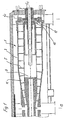
- FIG. 1 shows a three-phase solid bowl screw centrifuge 1 with a drum 3, in which a screw 5 is arranged.
- the drum 3 and the screw 5 each have a substantially cylindrical portion and a conically tapered portion here.
- An axially extending centric inlet pipe 7 serves to supply the centrifuged material via a distributor 9 into the centrifugal space 11 between the screw 5 and the drum 3.
- the screw 5 rotates at a slightly lower or greater speed than the drum 3 and promotes the ejected solid to the conical portion out of the drum 3 to the solids discharge 13.
- the liquid flows to the larger drum diameter at the rear end of the cylindrical portion of the drum 3 and is there by a first inner - ie Weir 15 and an outer second weir 17, which are closer to the axis of rotation, are derived in two separate liquid phases L1 and L2.
- the first inner ie the weir closer to the axis of rotation 15, has a passage 19 in an axial cover 21 of the drum 3, to which a paring disc 23 is arranged downstream in the outflow direction.
- the paring disc 23 is arranged in an inner annular space 25 of a ring piece 27 with a cylindrical projection 29, wherein the discharge of the liquid through the paring disc 23 in a channel 33 between the inner circumference of a likewise cylindrical projection 31 of the paring disc 23 and the outer circumference of the inlet tube 7 takes place ,
- the inner edge of the passage 19 in the radial direction of the cover 21 is offset radially inwardly relative to the inner circumference of the centrifugal space or relative to the outer circumference of the screw body.
- the first liquid phase is advantageously discharged under pressure.
- the first weir can - within certain limits - additionally adjust the liquid level (throttling).
- a control method for decanters describes the EP 0 868 215 B1 ,
- the use of peeling disk-like discharge organs (peeling head) in decanters is in principle from the DE 33 44 432 known, but not in the chosen combination of features with adjustable outer weirs.
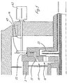
- the derivation of the second liquid phase L2 is carried out by the further weir 17, which has an adjustable throttle device 35, which is arranged downstream of a further radially outwardly in the cover 21 passage 37 which penetrates both the lid 21 and the ring member 27 axially.
- the adjustable throttle device 35 has a throttle plate 39 whose distance from the passage 29, for example, in the DE 43 20 265 A1 described manner is variable with a variety of drive devices.
- the throttle disk 39 is attached to one end of at least one bolt 41, which is here exemplarily axially displaceable by a motor 43 (also conceivable by hand), so that the distance between the stationary in operation throttle disk 39 and the at least one (or more) Passage 37 by axial movement, in particular by an axial displacement (also feasible by pivoting) of the throttle plate 39 is variable relative to the rotating drum 3 in operation.
- a motor 43 also conceivable by hand
- FIG. 3 largely corresponds to the FIG. 1 and 2
- the first weir 15 is not assigned to a paring disc, but it is designed as a simple adjustable overflow weir and has only the (in cross section, for example by a flap) adjustable, not visible here) passage 19 in the lid 21, of which the first liquid phase L1 free - and not under pressure - expires, so that if necessary, a pump for discharging the first liquid phase L 1 is provided.
- FIG. 4 is different from that of FIG. 3 in that the throttle disk 51 is indeed axially adjustable, but co-rotates with the drum.
- the drive (not shown) for axially adjusting the throttle slide 51 rotate relative to its holder 45 with the drum 3, which is the design effort and in particular the maintenance of the embodiment of the FIG. 2 significantly increased, but the possibility to control the heavy liquid phase obtained obese.
- a spring and / or hydraulic system (not shown) can be used for axial displacement of the throttle disk 51.
- the passage 37 (with any cross-section) in the ring piece 27 is guided axially outward, wherein instead of a throttle plate, a preferred throttle ring 47th is provided, which is axially displaceably guided over the radially outwardly directed passage opening 49 (again by means of an arrangement of axially adjustable bolt 41 and motor 43).
- a preferred throttle ring 47th is provided, which is axially displaceably guided over the radially outwardly directed passage opening 49 (again by means of an arrangement of axially adjustable bolt 41 and motor 43).
- This is by adjusting the position of the throttle ring - which must not be cylindrical but may have another shape eg with bevelled or chamfered inner circumference - relative to the passage opening 49, the cross section of the passage opening 49 more or less released and changed the flow rate of the second liquid phase L2 ,
Landscapes
- Centrifugal Separators (AREA)
Description
- Die Erfindung betrifft eine Dreiphasen-Vollmantel-Schneckenzentrifuge nach dem Oberbegriff des Anspruches 1 und ein Verfahren zum Betreiben einer solchen Dreiphasen-Vollmantel-Schneckenzentrifuge nach dem Obergriff des Anspruches 12.
- Aus der
EP 0 733 646 B1 ist eine Dreiphasen-Vollmantel-Schneckenzentrifuge bekannt, bei der eine schwere Flüssigkeitsphase aus Getreidekleber und Feinstärke und eine leichte Flüssigkeitsphase aus Wasser und löslichen Bestandteilen aus dem Schleuderraum ausgetragen werden. Dabei wird die schwere Flüssigkeitsphase über ein Schälsystem aufgeschlossen, während das Wasser der weiteren leichteren Flüssigkeitsphase über ein weiteres Trennsystem, insbesondere ein zweites Schälsystem abgeleitet wird. Alternativ kann die leichtere Flüssigkeitsphase über Wehreinrichtungen die Vollmantel-Schneckenzentrifuge in freiem Gefälle verlassen. Zwischen einer verstellbaren Schälscheibe des ersten Schälsystems und der Zentrifugentrommel wird eine hohe Differenz der Relativgeschwindigkeit eingestellt. - Dieser Stand der Technik bringt verschiedene Probleme mit sich. Die zwei Schälsysteme sind zusammen relativ teuer. Darüber hinaus existieren Produkte, welche mit Schälscheiben nur bedingt verarbeitbar sind, z.B. da sie die beiden Schälscheiben zusetzen. Problematisch ist aber vor allem, dass mit den beiden Schälscheiben eine Regelbarkeit der beiden Phasen hinsichtlich der Durchsatzmengen, insbesondere der schwereren Phase, nur eingeschränkt gegeben ist.
- Die Erfindung hat gegenüber diesem Stand der Technik der
EP 0 733 646 B1 die Aufgabe, die Dreiphasen-Vollmantel-Schneckenzentrifuge derart weiterzubilden, daß auf einfache und wartungsarme Weise ein präzises Einstellen der Ablaufmenge der schwereren Flüssigkeitsphase realisierbar ist. Es soll ferner ein vorteilhaftes und einfaches Verfahren zum Betreiben dieser Dreiphasen-Vollmantel-Schneckenzentrifuge geschaffen werden. - Zum Stand der Technik wird noch die
DE 41 30 759 A1 genannt. In der Schrift wird eine Zweiphasen-Vollmantel-Schneckenzentrifuge vorgestellt, die von einem Schließorgan verschließbare Restentleerungsöffnungen im äußeren Trommelmantel aufweist. - Aus der
WO 97/20634 - Die Erfindung erreicht dieses Ziel in Hinsicht auf die Dreiphasen-Vollmantel-Schnekkenzentrifuge durch den Gegenstand des Anspruches 1 und in Hinsicht auf das Verfahren durch den Gegenstand des Anspruches 12.
- In Hinsicht auf die Dreiphasenzentrifuge ist vorgesehen, daß das zweite Wehr zum Ableiten der schweren Flüssigkeitsphase einen Durchlaß aufweist, dem eine Drosseleinrichtung zugeordnet ist, deren Abstand zum Durchlaß veränderlich ist.
- In Hinsicht auf das Verfahren wird eine erste leichtere Flüssigkeitsphase über ein erstes, inneres Wehr und eine zweite, schwerere Flüssigkeitsphase über ein zweites, äußeres Wehr abgeleitet, wobei zum Verändern der Menge der ablaufenden schwereren Flüssigkeitsphase der Abstand einer Drosseleinrichtung zu einem Durchlass des zweiten Wehres verändert wird.
- Vorzugsweise ist die Drosseleinrichtung als im Betrieb der Zentrifuge stillstehendes Teil ausgebildet, und zwar vorzugsweise als Drosselscheibe, die sich nicht mit der Trommel mitdreht und relativ zum Auslaß radial verstellbar ist.
- Eine Drosseleinrichtung dieser Art ist zwar prinzipiell bereits aus der
DE 43 20 265 A1 bekannt. Die in dieser Schrift offenbarte Vollmantel-Schneckenzentrifuge ist an der Flüssigkeitsaustrittsseite mit einem Wehr versehen, welches einen Durchlaß aufweist, der durch mehrere vom Innendurchmesser des Wehres ausgehende Nuten oder durch in den Wandungen des Wehres vorgesehene Öffnungen gebildet sein kann. Dem Durchlaß ist eine während des Drehens der Trommel relativ zu dieser stillstehende Drosselscheibe zugeordnet, die über eine Gewindebuchse axial verschiebbar ist. Durch Verdrehen der Gewindebuchse kann der Abstand zwischen dem Wehr und der Drosselscheibe verändert werden. Dadurch verändert sich für die aus der Schleudertrommel ablaufende Flüssigkeit der Abflussquerschnitt, welcher sich auf den Flüssigkeitspegel in der Zentrifuge auswirkt. - Dieser Effekt spielt im Rahmen der Erfindung allerdings keine oder nur eine vemachlässigbare Rolle. Es gelingt vielmehr wider Erwarten, mit der Drosseleinrichtung auf einfache Weise lediglich eine Einstellung der Ablaufmenge der zweiten Flüssigkeitsphase bei einer Dreiphasenzentrifuge vorzunehmen. Denkbar ist es aber, ebenfalls das innere Wehr z.B. nach Art dieser Schrift auszubilden, d.h. den Abstand einer Drosseleinrichtung zu einem Durchlass des zweiten Wehres veränderlich zu gestalten.
- Mit der Erfindung wird es daher möglich, auch auf besonders einfache Weise durch Einstellung der Drosseleinrichtung die Austrittsmenge der schweren Flüssigkeitsphase zu regeln, z.B. in Abhängigkeit von der Dekanterzulaufmenge und/oder vom Drehmoment der Schnecke und/oder von der Differenzdrehzahl zwischen Schnecke und Trommel und/oder vom Motorstrom. Diese Regelung wird insbesondere automatisch und vorzugsweise mit einem der Zentrifuge zugeordneten Steuerungsrechner durchgeführt.
- Mit der Erfindung können dagegen durch die Regelung der schweren Flüssigkeitsphase auf besonders einfache Weise Schwankungen in der Zusammensetzung des zulaufenden Produktes ausgeglichen werden. Dies ist insbesondere bei Naturprodukten von Vorteil, da sich bei diesen Produkten häufig die Zusammensetzung des Inhaltsstoffe wie Stärke, Kleber, Schleimstoffe (Pentosane) usw. verändert.
- Während eine Anpassung der Differenzdrehzahl beim Betrieb der Zentrifuge an sich bekannt ist, musste zur Veränderung der Ablaufmenge der schweren Flüssigkeitsmenge z.B. beim Einsatz von Düsen die Zentrifuge gestoppt werden und eine andere Düse eingesetzt werden. Auch beim Einsatz eines zweiten Schälsystems für die schwerere Flüssigkeitsphase war eine Variation der Ablaufmenge der schweren Flüssigkeitsphase nur eingeschränkt möglich. Diese Variation kann jetzt in einfacherer und genauerer Weise und insbesondere auch unmittelbar während des Betriebes der Zentrifuge erfolgen.
- Dies hat im Betrieb erhebliche Vorteile, da gerade die Drei-Phasentechnik darauf abzielt, die Inhaltsstoffe der schweren Flüssigkeitsphase (z.B. Kleber, Feinstärke) von den Inhaltsstoffen der leichten Phase (z.B. Schleimstoffe, Pentosane) zu trennen. Da bisher keine zufriedenstellende automatische Regelung der schwereren Flüssigkeitsphase möglich war, gelangten bei einer Änderung der Produktbeschaffenheit während des Betriebs zu viele Inhaltsstoffe der einen (z.B. der leichten) Flüssigkeitsphase mit in die andere (z.B. schwerere Flüssigkeitsphase). Dies wird mit der Erfindung vermieden.
- Insbesondere von Vorteil ist die Erfindung und die mit ihr gegebene Regelbarkeit der schweren Flüssigkeitsphase bei der Verarbeitung von Produkten, bei welchen die Trägerflüssigkeit keine große Dichteunterschiede aufweist (im Gegensatz zum Beispiel zu Wasser/Öl), so dass sich oftmals keine deutliche Trennzone ausbildet.
- Die
DE 100 21 983 A1 schlägt bei einer verschwenkbaren, nichtmitrotierenden Drosselscheibe für eine Zweiphasenzentrifuge, welche auf dem Prinzip der Drosselscheibe derDE 43 20 265 A1 beruht, ergänzend vor, die Drosselscheibe mit einer ringförmigen Nut zu versehen, welche als "Ringtasse" bezeichnet wird. - Nach einer weniger bevorzugten Varianten, die konstruktiv aufwendiger ist, ist es auch denkbar, daß die Drosseleinrichtung als eine sich mit der Trommel mitrotierende Drosseleinrichtung, insbesondere Drosselscheibe, ausgebildet ist, deren Abstand zum Durchlass verstellbar ist. Aus der
EP 0 586 382 B1 ,Fig. 5 ist es bekannt, bei einer Dreiphasenzentrifuge mit zwei abzuleitenden Flüssigkeitsphasen dem inneren Wehr einen mitrotierenden, aufblasbaren Damm zuzuordnen. Ein aufpump- oder -blasbarer Damm ist zu diesem Zweck auch aus derDE 199 62 645 A1 bekannt. - Die Erfindung schafft ferner nach einem weiteren, auch unabhängig zu betrachtenden Gedanken eine Vollmantel-Schneckenzentrifuge mit wenigstens einem Wehr zum Ableiten einer Flüssigkeitsphase aus der Schleudertrommel, wobei das wenigstens eine Wehr einen Durchlass aufweist, dem eine Drosseleinrichtung zugeordnet ist, deren Abstand bzw. Position relativ zum Durchlass veränderlich ist, wobei die Drosseleinrichtung einen Drosselring aufweist, der über einer radial nach außen gerichteten Durchlassöffnung des Durchlasses derart beweglich, insbesondere verschieblich, geführt ist, daß durch Verstellen der Position des Drosselringes relativ zur Durchlassöffnung der Auslassquerschnitt an der Durchlassöffnung veränderlich ist.
- Diese Anordnung mit dem verschieblichen Drosselring (insbesondere auch ein zylindrisches, hülsenartiges Teil) über der einen oder mehreren im wesentlichen radial nach außen gerichteten Durchlassöffnung(en) eignet sich sowohl für die Ableitung der schwereren Phase aus einer Dreiphasenzentrifuge als auch zur Regelung des Flüssigkeitspegels in einer Zweiphasenzentrifuge mit nur einem einzigen Ablaufwehr.
- Besonders vorteilhaft ist, dass mit dem Drosselring eine besonders kompakte - insbesondere in Richtung der Trommellängsachse kurz bauende - Bauform einer Drosseleinrichtung realisiert wird.
- Der Drosselring wird vorteilhaft als im Betrieb relativ zur sich drehenden Trommel stillstehendes Teil ausgebildet. Diese Ausführungsform ist konstruktiv besonders einfach.
- Alternativ ist es bei einer weniger optimalen, da konstruktiv aufwendigeren Ausführungsform auch denkbar, dass der Drosselring als sich im Betrieb mit der Trommel mitdrehendes Teil ausgebildet ist.
- Weitere vorteilhafte Ausgestaltungen sind den übrigen Unteransprüchen zu entnehmen.
- Vorzugsweise wird die Austrittsmenge der schweren Flüssigkeitsphase automatisch geregelt.
- Nachfolgend werden Ausführungsbeispiele unter Bezug auf die Zeichnung näher beschrieben. Es zeigt:
- Figur 1
- eine erfindungsgemäße Vollmantel-Schneckenzentrifuge;
- Figur 2
- den Bereich des Wehres der Vollmantel-Schneckenzentrifuge aus
Figur 1 ; - Figur 3
- den Bereich des Wehres einer zweiten erfindungsgemäßen Vollmantel- Schneckenzentrifuge;
- Figur 4
- den Bereich des Wehres einer dritten erfindungsgemäßen Vollmantel- Schneckenzentrifuge und
- Figur 5
- den Bereich des Wehres einer vierten erfindungsgemäßen Vollmantel- Schneckenzentrifuge.
-
Figur 1 zeigt eine Dreiphasen-Vollmantel-Schneckenzentrifuge 1 mit einer Trommel 3, in der eine Schnecke 5 angeordnet ist. Die Trommel 3 und die Schnecke 5 weisen jeweils einen im wesentlichen zylindrischen Abschnitt und einen sich hier konisch verjüngenden Abschnitt auf. - Ein sich axial erstreckendes zentrisches Einlaufrohr 7 dient zur Zuleitung des Schleudergutes über einen Verteiler 9 in den Schleuderraum 11 zwischen der Schnecke 5 und der Trommel 3.
- Wird beispielsweise ein schlammiger Brei in die Zentrifuge geleitet, setzen sich an der Trommelwandung gröbere Feststoffpartikel ab. Weiter nach innen hin bildet sich eine Flüssigkeitsphase aus.
- Die Schnecke 5 rotiert mit einer etwas kleineren oder größeren Geschwindigkeit als die Trommel 3 und fördert den ausgeschleuderten Feststoff zum konischen Abschnitt hin aus der Trommel 3 zum Feststoffaustrag 13. Die Flüssigkeit strömt dagegen zum größeren Trommeldurchmesser am hinteren Ende des zylindrischen Abschnittes der Trommel 3 und wird dort durch ein erstes inneres - d.h. näher zur Rotationsachse liegendes - Wehr 15 und ein äußeres zweites Wehr 17 in zwei getrennten Flüssigkeitsphasen L1 und L2 abgeleitet.
- Der Bereich der Wehre 15 und 17 ist in
Fig. 2 vergrößert dargestellt. - Nach
Figur 2 weist das erste innere, d.h. das näher zur Rotationsachse liegende Wehr 15 einen Durchlass 19 in einem axialen Deckel 21 der Trommel 3 auf, dem in Ausflußrichtung eine Schälscheibe 23 nachgeordnet ist. - Die Schälscheibe 23 ist in einem inneren Ringraum 25 eines Ringstückes 27 mit einem zylindrischen Ansatz 29 angeordnet, wobei die Ableitung der Flüssigkeit durch die Schälscheibe 23 in einem Kanal 33 zwischen dem Innenumfang eines ebenfalls zylindrischen Ansatzes 31 der Schälscheibe 23 und dem Außenumfang des Zulaufrohres 7 erfolgt.
- Hier liegt die Innenkante des Durchlasses 19 in radialer Richtung des Deckels 21 relativ zum Innenumfang des Schleuderraumes bzw. relativ zum Außenumfang des Schneckenkörpers radial weiter nach innen hin versetzt.
- Durch die Schälscheibe 23 wird die erste Flüssigkeitsphase in vorteilhafter Weise unter Druck abgeleitet. Durch Einstellen des ersten Wehres kann - in gewissen Grenzen - ergänzend der Flüssigkeitsspiegel eingestellt werden (Androsseln). Ein Steuerungsverfahren für Dekanter beschreibt die
EP 0 868 215 B1 . Der Einsatz von schälscheibenartigen Ableitungsorganen (Schälkopf) bei Dekantern ist prinzipiell aus derDE 33 44 432 bekannt, nicht aber in der hier gewählten Merkmalskombination mit einstellbaren äußeren Wehren. - Die Ableitung der zweiten Flüssigkeitsphase L2 erfolgt durch das weitere Wehr 17, das eine verstellbare Drosseleinrichtung 35 aufweist, welche einem in radialer Richtung weiter außen im Deckel 21 angeordneten Durchlaß 37 nachgeordnet ist, der sowohl den Deckel 21 als auch das Ringstück 27 axial durchsetzt.
- Die verstellbare Drosseleinrichtung 35 weist eine Drosselscheibe 39 auf, deren Abstand zum Durchlaß 29 beispielsweise auf die in der
DE 43 20 265 A1 beschriebene Art und Weise mit verschiedensten Antriebseinrichtungen veränderlich ist. - Nach
Fig. 1 ist die Drosselscheibe 39 an einem Ende wenigstens eines Bolzens 41 befestigt, der hier beispielhaft axial mittels eines Motors 43 verschieblich geführt ist (auch von Hand denkbar), so daß der Abstand zwischen der im Betrieb stillstehenden Drosselscheibe 39 und dem wenigstens einen (oder mehreren) Durchlaß 37 durch axiales Bewegen, insbesondere durch ein axiales Verschieben (auch realisierbar durch ein Verschwenken) der Drosselscheibe 39 relativ zur sich im Betrieb drehenden Trommel 3 veränderlich ist wird. - Hervorzuheben ist, dass anders als nach der Lehre der
DE 43 20 265A1 hier die Drosseleinrichtung überraschenderweise nicht zur Einstellung der Flüssigkeitsspiegel in der Trommel sondern in erster Linie zur Einstellung der Ablaufmenge der zweiten Flüssigkeitsphase L2 dient. - Das Ausführungsbeispiel der
Figur 3 entspricht weitgehend dem derFigur 1 und2 , allerdings ist dem ersten Wehr 15 keine Schälscheibe zugeordnet, sondern es ist als einfaches einstellbares Überlaufwehr ausgebildet und weist lediglich den (im Querschnitt z.B. durch eine Klappe) einstellbaren, hier nicht erkennbar) Durchlaß 19 im Deckel 21 auf, von dem die erste Flüssigkeitsphase L1 frei - und nicht unter Druck - abläuft, so dass ggf. noch eine Pumpe zur Ableitung der ersten Flüssigkeitsphase L 1 vorzusehen ist. - Das Ausführungsbeispiel der
Figur 4 unterscheidet sich von dem derFigur 3 dadurch, daß die Drosselscheibe 51 zwar axial verstellbar ist, aber mit der Trommel mitrotiert. Anders als bei dem Ausführungsbeispiel derFigur 2 muß sich hier der Antrieb (nicht dargestellt) zum axialen Verstellen der Drosselschiebe 51 relativ zu ihrer Halterung 45 mit der Trommel 3 mitdrehen, was den konstruktiven Aufwand und insbesondere auch den Wartungsaufwand gegenüber dem Ausführungsbeispiel derFigur 2 deutlich erhöht, wobei aber die Möglichkeit zur Regelung der schweren Flüssigkeitsphase erhalten beleibt. Zum axialen Verschieben der Drosselscheibe 51 ist beispielsweise ein Feder- und/oder Hydrauliksystem (nicht dargestellt) nutzbar. - Nach
Figur 5 ist der Durchlaß 37 (mit beliebigem Querschnitt) im Ringstück 27 axial nach außen geführt, wobei anstelle einer Drosselscheibe ein bevorzugt Drosselring 47 vorgesehen ist, welcher über der radial nach außen gerichteten Durchlassöffnung 49 axial verschieblich geführt ist (wiederum mittels einer Anordnung aus axial verstellbarem Bolzen 41 und Motor 43). Damit wird durch Verstellen der Position des Drosselringes - der nicht zylindrisch sein muss sondern eine andere Form z.B. auch mit angeschrägtem oder angefasten inneren Umfang aufweisen kann - relativ zur Durchlassöffnung 49 der Querschnitt der Durchlassöffnung 49 mehr oder weniger freigegeben und die Ablaufmenge der zweiten Flüssigkeitsphase L2 verändert. -
Vollmantel-Schneckenzentrifuge 1 Trommel 3 Schnecke 5 Einlaufrohr 7 Verteiler 9 Schleuderraum 11 Feststoffaustrag 13 Wehr 15 Wehr 17 Durchlaß 19 Deckel 21 Schälscheibe 23 Ringraum 25 Ringstück 27 Ansatz 29 Durchlaß 29 Ansatz 31 Kanal 33 Drosseleinrichtung 35 Durchlass 37 Drosselscheibe 39 Bolzen 41 Motor 43 Halterung 45 Drosselring 47 Durchlassöffnung 49 Drosselscheibe 51 Durchlassöffnung 53 Flüssigkeitsphase L1 Flüssigkeitsphase L2
Claims (12)
- Dreiphasen-Vollmantel-Schneckenzentrifuge mit einem ersten, relativ zur Trommellängsachse inneren Wehr (15) zum Ableiten einer ersten, leichteren Flüssigkeitsphase (L1) sowie mit einem zweiten, äußeren Wehr (17) zum Ableiten einer zweiten, schwereren Flüssigkeitsphase (L2) aus der Schleudertrommel (3), dadurch gekennzeichnet, daßa) das zweite Wehr (17) einen Durchlaß (37) aufweist, dem eine Drosseleinrichtung (35) zugeordnet ist, deren Abstand zum Durchlaß (37) veränderlich ist,b) der Zentrifuge ein Steuerungsrechner zugeordnet ist, welcher dazu ausgelegt ist, durch Einstellung der Drosseleinrichtung die Austrittsmenge der schweren Flüssigkeitsphase rechnergesteuert zu regeln.
- Dreiphasen-Vollmantel-Schneckenzentrifuge nach Anspruch 1, dadurch gekennzeichnet, daß die Regelung automatisch in Abhängigkeit von der Dekanterzulaufmenge und/oder vom Drehmoment der Schnecke und/oder von der Differenzdrehzahl zwischen Schnecke und Trommel und/oder vom Motorstrom erfolgt.
- Dreiphasen-Vollmantel-Schneckenzentrifuge nach Anspruch 1 oder 2, dadurch gekennzeichnet, daß die Drosseleinrichtung (35) eine relativ zum Durchlaß (37) verstellbare Drosselscheibe (39 aufweist, die als im Betrieb der Zentrifuge stillstehendes Teil ausgebildet ist.
- Dreiphasen-Vollmantel-Schneckenzentrifuge nach Anspruch 3, dadurch gekennzeichnet, daß der Abstand der Drosselscheibe (39) zum Durchlaß (37) durch axiales Verschieben der Drosselscheibe (39) relativ zum Durchlaß (37) veränderlich ist.
- Dreiphasen-Vollmantel-Schneckenzentrifuge nach Anspruch 1 oder 2, dadurch gekennzeichnet, daß die Drosseleinrichtung (35) eine sich mit der Trommel (3) mitrotierende Drosseleinrichtung, insbesondere eine Drosselscheibe (51) aufweist, deren Abstand zum Durchlaß (37) verstellbar ist.
- Dreiphasen-Vollmantel-Schneckenzentrifuge nach einem der vorstehenden Ansprüche, dadurch gekennzeichnet, daß die Drosseleinrichtung einen Drosselring (47) aufweist, der über einer radial nach außen gerichteten Durchlassöffnung (53) des Durchlasses (37) beweglich, insbesondere verschieblich, geführt ist.
- Dreiphasen-Vollmantel-Schneckenzentrifuge nach einem der vorstehenden Ansprüche, dadurch gekennzeichnet, daß das erste, näher zur Rotationsachse der Trommel (3) liegende Wehr (15) einen inneren Durchlaß (19) in einem axialen Deckel (21) der Trommel (3) aufweist.
- Dreiphasen-Vollmantel-Schneckenzentrifuge nach einem der vorstehenden Ansprüche, dadurch gekennzeichnet, daß der Querschnitt des inneren und/oder äußeren Durchlasses (19, 37) veränderlich ist.
- Dreiphasen-Vollmantel-Schneckenzentrifuge nach einem der vorstehenden Ansprüche, dadurch gekennzeichnet, daß dem Durchlaß (19) in Ausflußrichtung eine Schälscheibe (23) nachgeordnet ist oder eine Drosseleinrichtung, deren Abstand relativ zum Durchlass (19) veränderlich ist.
- Verfahren zum Betreiben einer Dreiphasen-Vollmantel-Schneckenzentrifuge nach einem der Ansprüche 1 bis 9, bei dem eine erste leichtere Flüssigkeitsphase (L1) über ein erstes, inneres Wehr (15) und eine zweite, schwerere Flüssigkeitsphase über ein zweites, äußeres Wehr (17) abgeleitet wird, dadurch gekennzeichnet, daß zum Verändern der Menge der ablaufenden schwereren Flüssigkeitsphase (L2) der Abstand einer Drosseleinrichtung (35) zu einem Durchlaß (37) des zweiten Wehres (17) verändert wird, wobei der Zentrifuge ein Steuerungsrechner zugeordnet ist, welcher dazu verwendet wird, durch Einstellung der Drosseleinrichtung die Austrittsmenge der schweren Flüssigkeitsphase rechnergesteuert zu regeln.
- Verfahren nach Anspruch 10, dadurch gekennzeichnet, dass die Austrittsmenge der schweren Flüssigkeitsphase automatisch geregelt wird.
- Verfahren nach Anspruch 11, dadurch gekennzeichnet, dass die Austrittsmenge der schweren Flüssigkeitsphase in Abhängigkeit von der Dekanterzulaufmenge und/oder vom Drehmoment der Schnecke und/oder in Abhängigkeit von der Differenzdrehzahl zwischen der Schnecke und der Trommel und/oder in Abhängigkeit vom Motorstrom geregelt wird.
Applications Claiming Priority (3)
| Application Number | Priority Date | Filing Date | Title |
|---|---|---|---|
| DE10209925A DE10209925B4 (de) | 2002-03-07 | 2002-03-07 | Dreiphasen-Vollmantel-Schneckenzentrifuge, Vollmantel-Schneckenzentrifuge und Verfahren zum Betreiben einer Dreiphasen-Vollmantel-Schneckenzentrifuge |
| DE10209925 | 2002-03-07 | ||
| PCT/EP2003/002237 WO2003074185A1 (de) | 2002-03-07 | 2003-03-05 | Dreiphasen-vollmantel-schneckenzentrifuge, vollmantel-schneckenzentrifuge und verfahren zum betreiben einer dreiphasen-vollmantel-schneckenzentrifuge |
Publications (2)
| Publication Number | Publication Date |
|---|---|
| EP1480754A1 EP1480754A1 (de) | 2004-12-01 |
| EP1480754B1 true EP1480754B1 (de) | 2010-04-28 |
Family
ID=27771050
Family Applications (1)
| Application Number | Title | Priority Date | Filing Date |
|---|---|---|---|
| EP03711925A Expired - Lifetime EP1480754B1 (de) | 2002-03-07 | 2003-03-05 | Dreiphasen-vollmantel-schneckenzentrifuge, vollmantel-schneckenzentrifuge und verfahren zum betreiben einer dreiphasen-vollmantel-schneckenzentrifuge |
Country Status (7)
| Country | Link |
|---|---|
| EP (1) | EP1480754B1 (de) |
| AT (1) | ATE465814T1 (de) |
| AU (1) | AU2003218690A1 (de) |
| DE (2) | DE10209925B4 (de) |
| DK (1) | DK1480754T3 (de) |
| ES (1) | ES2344409T3 (de) |
| WO (1) | WO2003074185A1 (de) |
Cited By (1)
| Publication number | Priority date | Publication date | Assignee | Title |
|---|---|---|---|---|
| CN103189144A (zh) * | 2010-11-12 | 2013-07-03 | 阿尔法拉瓦尔股份有限公司 | 离心分离器 |
Families Citing this family (18)
| Publication number | Priority date | Publication date | Assignee | Title |
|---|---|---|---|---|
| DE10203652B4 (de) * | 2002-01-30 | 2006-10-19 | Westfalia Separator Ag | Vollmantel-Schneckenzentrifuge mit einem Wehr |
| DE10336350B4 (de) | 2003-08-08 | 2007-10-31 | Westfalia Separator Ag | Vollmantel-Schneckenzentrifuge, mit Schälscheibe |
| US7255670B2 (en) * | 2004-03-04 | 2007-08-14 | Hutchison Hayes, L.P. | Three phase decanter centrifuge |
| DE102005027553A1 (de) * | 2005-06-14 | 2006-12-28 | Westfalia Separator Ag | Drei-Phasen-Vollmantel-Schneckenzentrifuge und Verfahren zur Regelung des Trennprozesses |
| DE102006030477A1 (de) * | 2006-03-30 | 2007-10-04 | Westfalia Separator Ag | Vollmantel-Schneckenzentrifuge mit Abflußöffnungen zur Teil- und Restentleerung der Trommel |
| US8192342B2 (en) | 2006-05-11 | 2012-06-05 | Westfalia Separator Ag | Separator having a liquid outlet including a throttling device |
| DK200800555A (en) | 2008-04-16 | 2009-10-17 | Alfa Laval Corp Ab | Centrifugal separator |
| US8579783B2 (en) * | 2009-07-02 | 2013-11-12 | Andritz S.A.S. | Weir and choke plate for solid bowl centrifuge |
| DK178253B1 (en) | 2010-11-12 | 2015-10-12 | Alfa Laval Corp Ab | A centrifugal separator and an outlet element for a centrifugal separator |
| CN103316782A (zh) * | 2013-07-05 | 2013-09-25 | 安徽赛而特离心机有限公司 | 一种三相碟式分离机转鼓组 |
| GB201321250D0 (en) | 2013-12-02 | 2014-01-15 | Gm Innovations Ltd | An apparatus for removing impurities from a fluid stream |
| GB201703110D0 (en) | 2017-02-27 | 2017-04-12 | Gm Innovations Ltd | An apparatus for seperating components of a fluid stream |
| GB2572331B (en) | 2018-03-26 | 2022-03-09 | Gm Innovations Ltd | An apparatus for separating components of a fluid stream |
| GB2606484A (en) | 2018-04-24 | 2022-11-09 | Gm Innovations Ltd | An apparatus for producing potable water |
| WO2020176806A1 (en) | 2019-02-27 | 2020-09-03 | 3-Delta, Inc. | Compositions that contain lipophilic plant material and surfactant, and related methods |
| US12264296B2 (en) | 2020-09-02 | 2025-04-01 | Michael V. Zumpano | Compositions that contain lipophilic plant material and surfactant, and related methods |
| DE102022100511A1 (de) | 2022-01-11 | 2023-07-13 | Gea Westfalia Separator Group Gmbh | Vollmantel-Schneckenzentrifuge und Verfahren zur Regelung des Trennprozesses der Vollmantel-Schneckenzentrifuge |
| DE102023126610A1 (de) * | 2023-09-29 | 2025-04-03 | Gea Westfalia Separator Group Gmbh | Vollmantel-Zentrifuge |
Family Cites Families (7)
| Publication number | Priority date | Publication date | Assignee | Title |
|---|---|---|---|---|
| DE3344432C2 (de) * | 1983-12-08 | 1987-04-23 | Flottweg-Werk Bird Machine GmbH, 8313 Vilsbiburg | Zentrifuge zur Trennung einer Suspension mit zwei getrennt abzuführenden Flüssigkeitsphasen |
| US5257968A (en) * | 1991-06-06 | 1993-11-02 | Alfa Laval Separation Inc. | Inflatable dam for a decanter centrifuge |
| DE4130759A1 (de) * | 1991-09-16 | 1993-03-18 | Flottweg Gmbh | Zentrifuge zur kontinuierlichen trennung von stoffen unterschiedlicher dichte |
| DE4320265C2 (de) * | 1993-06-18 | 1995-08-03 | Westfalia Separator Ag | Wehr für Vollmantelschleudertrommeln |
| EP0868215B1 (de) * | 1995-12-01 | 2002-01-30 | Baker Hughes Incorporated | Verfahren und vorrichtung zum regeln und überwachen einer durchlaufzentrifuge |
| DE19962645C2 (de) * | 1999-12-23 | 2003-04-30 | Flottweg Gmbh | Wehreinrichtung für eine Zentrifuge |
| DE10021983A1 (de) * | 2000-05-05 | 2001-11-08 | Baker Hughes De Gmbh | Vollmantelzentrifuge zur Trennung von Feststoff-Flüssigkeitsgemischen |
-
2002
- 2002-03-07 DE DE10209925A patent/DE10209925B4/de not_active Expired - Fee Related
-
2003
- 2003-03-05 EP EP03711925A patent/EP1480754B1/de not_active Expired - Lifetime
- 2003-03-05 WO PCT/EP2003/002237 patent/WO2003074185A1/de not_active Ceased
- 2003-03-05 AU AU2003218690A patent/AU2003218690A1/en not_active Abandoned
- 2003-03-05 ES ES03711925T patent/ES2344409T3/es not_active Expired - Lifetime
- 2003-03-05 DK DK03711925.2T patent/DK1480754T3/da active
- 2003-03-05 DE DE50312663T patent/DE50312663D1/de not_active Expired - Lifetime
- 2003-03-05 AT AT03711925T patent/ATE465814T1/de active
Cited By (3)
| Publication number | Priority date | Publication date | Assignee | Title |
|---|---|---|---|---|
| CN103189144A (zh) * | 2010-11-12 | 2013-07-03 | 阿尔法拉瓦尔股份有限公司 | 离心分离器 |
| CN103189144B (zh) * | 2010-11-12 | 2014-10-29 | 阿尔法拉瓦尔股份有限公司 | 离心分离器 |
| US9352338B2 (en) | 2010-11-12 | 2016-05-31 | Alfa Laval Corporate Ab | Centrifugal separator with a casing sealing arrangement |
Also Published As
| Publication number | Publication date |
|---|---|
| WO2003074185A1 (de) | 2003-09-12 |
| ATE465814T1 (de) | 2010-05-15 |
| DE10209925A1 (de) | 2003-09-25 |
| ES2344409T3 (es) | 2010-08-26 |
| AU2003218690A1 (en) | 2003-09-16 |
| DK1480754T3 (da) | 2010-08-16 |
| DE50312663D1 (de) | 2010-06-10 |
| EP1480754A1 (de) | 2004-12-01 |
| DE10209925B4 (de) | 2010-06-17 |
Similar Documents
| Publication | Publication Date | Title |
|---|---|---|
| EP1480754B1 (de) | Dreiphasen-vollmantel-schneckenzentrifuge, vollmantel-schneckenzentrifuge und verfahren zum betreiben einer dreiphasen-vollmantel-schneckenzentrifuge | |
| DE10336350B4 (de) | Vollmantel-Schneckenzentrifuge, mit Schälscheibe | |
| DE69315109T2 (de) | Schneckenzentrifuge mit unterbrochenen Schneckenwendeln im konischen Austragsmantelteil | |
| DE10203652B4 (de) | Vollmantel-Schneckenzentrifuge mit einem Wehr | |
| EP2015871B1 (de) | Drei-phasen-trennseparator mit einer schälscheibe und feststoffaustragsöffnungen | |
| EP1345700B1 (de) | Vollmantel-schneckenzentrifuge mit tellereinsatz | |
| EP1901849B1 (de) | Drei-phasen-vollmantel-schneckenzentrifuge und verfahren zur regelung des trennprozesses | |
| EP3426405A1 (de) | Separator | |
| EP1585599B1 (de) | Vollmantel-schneckenzentrifuge mit einstellbarem feststoffaustrag | |
| WO2019170586A1 (de) | Vollmantel-schneckenzentrifuge | |
| DE4112957A1 (de) | Vollmantel-schneckenzentrifuge | |
| EP4463268A1 (de) | Vollmantel-schneckenzentrifuge und verfahren zur regelung des trennprozesses der vollmantel-schneckenzentrifuge | |
| DE102005021331A1 (de) | Drei-Phasen-Trennseparator mit einer Schälscheibe und Feststoffaustragsöffnungen | |
| EP1998896B1 (de) | Vollmantel-schneckenzentrifuge mit abflussöffnungen zur teil- und restentleerung der trommel | |
| WO2025032043A1 (de) | Vollmantel-zentrifuge | |
| DE19962645C2 (de) | Wehreinrichtung für eine Zentrifuge | |
| DE102016115557A1 (de) | Zentrifuge mit einer Schälscheibe | |
| EP1949966B1 (de) | Vollmantel-Schneckenzentrifuge mit einer Stauscheibe | |
| DE1020575B (de) | Kontinuierlich arbeitende Vollmantel-Zentrifuge mit Feststoffaustrag durch eine Transportschnecke | |
| DE19949194C2 (de) | Vollmantelschneckenzentrifuge mit einem Stauwehr | |
| DE202024106729U1 (de) | Vollmantel-Zentrifuge | |
| DE19949194A9 (de) | Vollmantelschneckenzentrifuge mit einem Stauwehr | |
| WO2025181150A1 (de) | Tellerseparator zur zentrifugalen verarbeitung einer suspension | |
| DE102024131506A1 (de) | Vollmantel-Schneckenzentrifuge und Verfahren zum Wechseln des Verteilers der Vollmantel-Schneckenzentrifuge | |
| DE102007003071A1 (de) | Verfahren zur Phasentrennung eines Produktes mit einer Zentrifuge und Separator |
Legal Events
| Date | Code | Title | Description |
|---|---|---|---|
| PUAI | Public reference made under article 153(3) epc to a published international application that has entered the european phase |
Free format text: ORIGINAL CODE: 0009012 |
|
| 17P | Request for examination filed |
Effective date: 20040716 |
|
| AK | Designated contracting states |
Kind code of ref document: A1 Designated state(s): AT BE BG CH CY CZ DE DK EE ES FI FR GB GR HU IE IT LI LU MC NL PT RO SE SI SK TR |
|
| RIN1 | Information on inventor provided before grant (corrected) |
Inventor name: BEIMANN, UDO Inventor name: SANDFORT, DANIEL Inventor name: HORSTKOETTER, LUDGER Inventor name: OSTKAMP, WILHELM Inventor name: HORBACH DR., ULRICH Inventor name: KUNZ, HERBERT |
|
| 17Q | First examination report despatched |
Effective date: 20070423 |
|
| RAP1 | Party data changed (applicant data changed or rights of an application transferred) |
Owner name: WESTFALIA SEPARATOR GMBH |
|
| RAP1 | Party data changed (applicant data changed or rights of an application transferred) |
Owner name: GEA WESTFALIA SEPARATOR GMBH |
|
| GRAP | Despatch of communication of intention to grant a patent |
Free format text: ORIGINAL CODE: EPIDOSNIGR1 |
|
| GRAC | Information related to communication of intention to grant a patent modified |
Free format text: ORIGINAL CODE: EPIDOSCIGR1 |
|
| GRAS | Grant fee paid |
Free format text: ORIGINAL CODE: EPIDOSNIGR3 |
|
| GRAA | (expected) grant |
Free format text: ORIGINAL CODE: 0009210 |
|
| AK | Designated contracting states |
Kind code of ref document: B1 Designated state(s): AT BE BG CH CY CZ DE DK EE ES FI FR GB GR HU IE IT LI LU MC NL PT RO SE SI SK TR |
|
| REG | Reference to a national code |
Ref country code: GB Ref legal event code: FG4D Free format text: NOT ENGLISH |
|
| REG | Reference to a national code |
Ref country code: CH Ref legal event code: EP |
|
| REG | Reference to a national code |
Ref country code: IE Ref legal event code: FG4D Free format text: LANGUAGE OF EP DOCUMENT: GERMAN |
|
| REF | Corresponds to: |
Ref document number: 50312663 Country of ref document: DE Date of ref document: 20100610 Kind code of ref document: P |
|
| REG | Reference to a national code |
Ref country code: SE Ref legal event code: TRGR |
|
| REG | Reference to a national code |
Ref country code: NL Ref legal event code: T3 |
|
| REG | Reference to a national code |
Ref country code: DK Ref legal event code: T3 |
|
| REG | Reference to a national code |
Ref country code: ES Ref legal event code: FG2A Ref document number: 2344409 Country of ref document: ES Kind code of ref document: T3 |
|
| REG | Reference to a national code |
Ref country code: IE Ref legal event code: FD4D |
|
| PG25 | Lapsed in a contracting state [announced via postgrant information from national office to epo] |
Ref country code: SI Free format text: LAPSE BECAUSE OF FAILURE TO SUBMIT A TRANSLATION OF THE DESCRIPTION OR TO PAY THE FEE WITHIN THE PRESCRIBED TIME-LIMIT Effective date: 20100428 |
|
| PG25 | Lapsed in a contracting state [announced via postgrant information from national office to epo] |
Ref country code: CY Free format text: LAPSE BECAUSE OF FAILURE TO SUBMIT A TRANSLATION OF THE DESCRIPTION OR TO PAY THE FEE WITHIN THE PRESCRIBED TIME-LIMIT Effective date: 20100428 Ref country code: GR Free format text: LAPSE BECAUSE OF FAILURE TO SUBMIT A TRANSLATION OF THE DESCRIPTION OR TO PAY THE FEE WITHIN THE PRESCRIBED TIME-LIMIT Effective date: 20100729 |
|
| PG25 | Lapsed in a contracting state [announced via postgrant information from national office to epo] |
Ref country code: EE Free format text: LAPSE BECAUSE OF FAILURE TO SUBMIT A TRANSLATION OF THE DESCRIPTION OR TO PAY THE FEE WITHIN THE PRESCRIBED TIME-LIMIT Effective date: 20100428 Ref country code: IE Free format text: LAPSE BECAUSE OF FAILURE TO SUBMIT A TRANSLATION OF THE DESCRIPTION OR TO PAY THE FEE WITHIN THE PRESCRIBED TIME-LIMIT Effective date: 20100428 Ref country code: PT Free format text: LAPSE BECAUSE OF FAILURE TO SUBMIT A TRANSLATION OF THE DESCRIPTION OR TO PAY THE FEE WITHIN THE PRESCRIBED TIME-LIMIT Effective date: 20100830 |
|
| PG25 | Lapsed in a contracting state [announced via postgrant information from national office to epo] |
Ref country code: RO Free format text: LAPSE BECAUSE OF FAILURE TO SUBMIT A TRANSLATION OF THE DESCRIPTION OR TO PAY THE FEE WITHIN THE PRESCRIBED TIME-LIMIT Effective date: 20100428 Ref country code: SK Free format text: LAPSE BECAUSE OF FAILURE TO SUBMIT A TRANSLATION OF THE DESCRIPTION OR TO PAY THE FEE WITHIN THE PRESCRIBED TIME-LIMIT Effective date: 20100428 Ref country code: CZ Free format text: LAPSE BECAUSE OF FAILURE TO SUBMIT A TRANSLATION OF THE DESCRIPTION OR TO PAY THE FEE WITHIN THE PRESCRIBED TIME-LIMIT Effective date: 20100428 |
|
| PLBE | No opposition filed within time limit |
Free format text: ORIGINAL CODE: 0009261 |
|
| STAA | Information on the status of an ep patent application or granted ep patent |
Free format text: STATUS: NO OPPOSITION FILED WITHIN TIME LIMIT |
|
| 26N | No opposition filed |
Effective date: 20110131 |
|
| PGRI | Patent reinstated in contracting state [announced from national office to epo] |
Ref country code: IT Effective date: 20110501 |
|
| PG25 | Lapsed in a contracting state [announced via postgrant information from national office to epo] |
Ref country code: MC Free format text: LAPSE BECAUSE OF NON-PAYMENT OF DUE FEES Effective date: 20110331 |
|
| REG | Reference to a national code |
Ref country code: CH Ref legal event code: PL |
|
| PG25 | Lapsed in a contracting state [announced via postgrant information from national office to epo] |
Ref country code: CH Free format text: LAPSE BECAUSE OF NON-PAYMENT OF DUE FEES Effective date: 20110331 Ref country code: LI Free format text: LAPSE BECAUSE OF NON-PAYMENT OF DUE FEES Effective date: 20110331 |
|
| PG25 | Lapsed in a contracting state [announced via postgrant information from national office to epo] |
Ref country code: LU Free format text: LAPSE BECAUSE OF NON-PAYMENT OF DUE FEES Effective date: 20110305 |
|
| PG25 | Lapsed in a contracting state [announced via postgrant information from national office to epo] |
Ref country code: BG Free format text: LAPSE BECAUSE OF FAILURE TO SUBMIT A TRANSLATION OF THE DESCRIPTION OR TO PAY THE FEE WITHIN THE PRESCRIBED TIME-LIMIT Effective date: 20100728 |
|
| PG25 | Lapsed in a contracting state [announced via postgrant information from national office to epo] |
Ref country code: HU Free format text: LAPSE BECAUSE OF FAILURE TO SUBMIT A TRANSLATION OF THE DESCRIPTION OR TO PAY THE FEE WITHIN THE PRESCRIBED TIME-LIMIT Effective date: 20100428 |
|
| REG | Reference to a national code |
Ref country code: FR Ref legal event code: PLFP Year of fee payment: 14 |
|
| PGFP | Annual fee paid to national office [announced via postgrant information from national office to epo] |
Ref country code: DK Payment date: 20160318 Year of fee payment: 14 Ref country code: NL Payment date: 20160317 Year of fee payment: 14 Ref country code: TR Payment date: 20160229 Year of fee payment: 14 Ref country code: ES Payment date: 20160322 Year of fee payment: 14 |
|
| PGFP | Annual fee paid to national office [announced via postgrant information from national office to epo] |
Ref country code: BE Payment date: 20160317 Year of fee payment: 14 Ref country code: GB Payment date: 20160321 Year of fee payment: 14 Ref country code: AT Payment date: 20160324 Year of fee payment: 14 Ref country code: SE Payment date: 20160318 Year of fee payment: 14 Ref country code: FI Payment date: 20160322 Year of fee payment: 14 Ref country code: FR Payment date: 20160328 Year of fee payment: 14 |
|
| PGFP | Annual fee paid to national office [announced via postgrant information from national office to epo] |
Ref country code: DE Payment date: 20160331 Year of fee payment: 14 |
|
| PGFP | Annual fee paid to national office [announced via postgrant information from national office to epo] |
Ref country code: IT Payment date: 20160331 Year of fee payment: 14 |
|
| REG | Reference to a national code |
Ref country code: DE Ref legal event code: R119 Ref document number: 50312663 Country of ref document: DE |
|
| REG | Reference to a national code |
Ref country code: DK Ref legal event code: EBP Effective date: 20170331 |
|
| PG25 | Lapsed in a contracting state [announced via postgrant information from national office to epo] |
Ref country code: FI Free format text: LAPSE BECAUSE OF NON-PAYMENT OF DUE FEES Effective date: 20170305 |
|
| REG | Reference to a national code |
Ref country code: SE Ref legal event code: EUG |
|
| REG | Reference to a national code |
Ref country code: NL Ref legal event code: MM Effective date: 20170401 |
|
| REG | Reference to a national code |
Ref country code: AT Ref legal event code: MM01 Ref document number: 465814 Country of ref document: AT Kind code of ref document: T Effective date: 20170305 |
|
| GBPC | Gb: european patent ceased through non-payment of renewal fee |
Effective date: 20170305 |
|
| PG25 | Lapsed in a contracting state [announced via postgrant information from national office to epo] |
Ref country code: SE Free format text: LAPSE BECAUSE OF NON-PAYMENT OF DUE FEES Effective date: 20170306 |
|
| REG | Reference to a national code |
Ref country code: FR Ref legal event code: ST Effective date: 20171130 |
|
| PG25 | Lapsed in a contracting state [announced via postgrant information from national office to epo] |
Ref country code: NL Free format text: LAPSE BECAUSE OF NON-PAYMENT OF DUE FEES Effective date: 20170401 Ref country code: DE Free format text: LAPSE BECAUSE OF NON-PAYMENT OF DUE FEES Effective date: 20171003 Ref country code: AT Free format text: LAPSE BECAUSE OF NON-PAYMENT OF DUE FEES Effective date: 20170305 Ref country code: FR Free format text: LAPSE BECAUSE OF NON-PAYMENT OF DUE FEES Effective date: 20170331 |
|
| PG25 | Lapsed in a contracting state [announced via postgrant information from national office to epo] |
Ref country code: GB Free format text: LAPSE BECAUSE OF NON-PAYMENT OF DUE FEES Effective date: 20170305 Ref country code: IT Free format text: LAPSE BECAUSE OF NON-PAYMENT OF DUE FEES Effective date: 20170305 |
|
| REG | Reference to a national code |
Ref country code: BE Ref legal event code: MM Effective date: 20170331 |
|
| PG25 | Lapsed in a contracting state [announced via postgrant information from national office to epo] |
Ref country code: DK Free format text: LAPSE BECAUSE OF NON-PAYMENT OF DUE FEES Effective date: 20170331 |
|
| PG25 | Lapsed in a contracting state [announced via postgrant information from national office to epo] |
Ref country code: BE Free format text: LAPSE BECAUSE OF NON-PAYMENT OF DUE FEES Effective date: 20170331 |
|
| REG | Reference to a national code |
Ref country code: ES Ref legal event code: FD2A Effective date: 20180706 |
|
| PG25 | Lapsed in a contracting state [announced via postgrant information from national office to epo] |
Ref country code: ES Free format text: LAPSE BECAUSE OF NON-PAYMENT OF DUE FEES Effective date: 20170306 |
|
| PG25 | Lapsed in a contracting state [announced via postgrant information from national office to epo] |
Ref country code: TR Free format text: LAPSE BECAUSE OF NON-PAYMENT OF DUE FEES Effective date: 20170305 |