EP1479982B1 - Belüftungseinrichtung - Google Patents
Belüftungseinrichtung Download PDFInfo
- Publication number
- EP1479982B1 EP1479982B1 EP03076572A EP03076572A EP1479982B1 EP 1479982 B1 EP1479982 B1 EP 1479982B1 EP 03076572 A EP03076572 A EP 03076572A EP 03076572 A EP03076572 A EP 03076572A EP 1479982 B1 EP1479982 B1 EP 1479982B1
- Authority
- EP
- European Patent Office
- Prior art keywords
- channel
- chamber
- air
- ventilation system
- inlet
- Prior art date
- Legal status (The legal status is an assumption and is not a legal conclusion. Google has not performed a legal analysis and makes no representation as to the accuracy of the status listed.)
- Expired - Lifetime
Links
Images
Classifications
-
- F—MECHANICAL ENGINEERING; LIGHTING; HEATING; WEAPONS; BLASTING
- F24—HEATING; RANGES; VENTILATING
- F24F—AIR-CONDITIONING; AIR-HUMIDIFICATION; VENTILATION; USE OF AIR CURRENTS FOR SCREENING
- F24F11/00—Control or safety arrangements
- F24F11/0001—Control or safety arrangements for ventilation
-
- F—MECHANICAL ENGINEERING; LIGHTING; HEATING; WEAPONS; BLASTING
- F28—HEAT EXCHANGE IN GENERAL
- F28F—DETAILS OF HEAT-EXCHANGE AND HEAT-TRANSFER APPARATUS, OF GENERAL APPLICATION
- F28F3/00—Plate-like or laminated elements; Assemblies of plate-like or laminated elements
- F28F3/02—Elements or assemblies thereof with means for increasing heat-transfer area, e.g. with fins, with recesses, with corrugations
- F28F3/022—Elements or assemblies thereof with means for increasing heat-transfer area, e.g. with fins, with recesses, with corrugations the means being wires or pins
-
- F—MECHANICAL ENGINEERING; LIGHTING; HEATING; WEAPONS; BLASTING
- F24—HEATING; RANGES; VENTILATING
- F24F—AIR-CONDITIONING; AIR-HUMIDIFICATION; VENTILATION; USE OF AIR CURRENTS FOR SCREENING
- F24F11/00—Control or safety arrangements
- F24F11/30—Control or safety arrangements for purposes related to the operation of the system, e.g. for safety or monitoring
- F24F11/46—Improving electric energy efficiency or saving
-
- F—MECHANICAL ENGINEERING; LIGHTING; HEATING; WEAPONS; BLASTING
- F24—HEATING; RANGES; VENTILATING
- F24F—AIR-CONDITIONING; AIR-HUMIDIFICATION; VENTILATION; USE OF AIR CURRENTS FOR SCREENING
- F24F11/00—Control or safety arrangements
- F24F11/70—Control systems characterised by their outputs; Constructional details thereof
- F24F11/72—Control systems characterised by their outputs; Constructional details thereof for controlling the supply of treated air, e.g. its pressure
- F24F11/74—Control systems characterised by their outputs; Constructional details thereof for controlling the supply of treated air, e.g. its pressure for controlling air flow rate or air velocity
- F24F11/76—Control systems characterised by their outputs; Constructional details thereof for controlling the supply of treated air, e.g. its pressure for controlling air flow rate or air velocity by means responsive to temperature, e.g. bimetal springs
-
- F—MECHANICAL ENGINEERING; LIGHTING; HEATING; WEAPONS; BLASTING
- F24—HEATING; RANGES; VENTILATING
- F24F—AIR-CONDITIONING; AIR-HUMIDIFICATION; VENTILATION; USE OF AIR CURRENTS FOR SCREENING
- F24F11/00—Control or safety arrangements
- F24F11/70—Control systems characterised by their outputs; Constructional details thereof
- F24F11/72—Control systems characterised by their outputs; Constructional details thereof for controlling the supply of treated air, e.g. its pressure
- F24F11/74—Control systems characterised by their outputs; Constructional details thereof for controlling the supply of treated air, e.g. its pressure for controlling air flow rate or air velocity
- F24F11/77—Control systems characterised by their outputs; Constructional details thereof for controlling the supply of treated air, e.g. its pressure for controlling air flow rate or air velocity by controlling the speed of ventilators
-
- F—MECHANICAL ENGINEERING; LIGHTING; HEATING; WEAPONS; BLASTING
- F24—HEATING; RANGES; VENTILATING
- F24F—AIR-CONDITIONING; AIR-HUMIDIFICATION; VENTILATION; USE OF AIR CURRENTS FOR SCREENING
- F24F12/00—Use of energy recovery systems in air conditioning, ventilation or screening
- F24F12/001—Use of energy recovery systems in air conditioning, ventilation or screening with heat-exchange between supplied and exhausted air
- F24F12/006—Use of energy recovery systems in air conditioning, ventilation or screening with heat-exchange between supplied and exhausted air using an air-to-air heat exchanger
-
- F—MECHANICAL ENGINEERING; LIGHTING; HEATING; WEAPONS; BLASTING
- F24—HEATING; RANGES; VENTILATING
- F24F—AIR-CONDITIONING; AIR-HUMIDIFICATION; VENTILATION; USE OF AIR CURRENTS FOR SCREENING
- F24F7/00—Ventilation
- F24F7/04—Ventilation with ducting systems, e.g. by double walls; with natural circulation
- F24F7/06—Ventilation with ducting systems, e.g. by double walls; with natural circulation with forced air circulation, e.g. by fan positioning of a ventilator in or against a conduit
- F24F7/08—Ventilation with ducting systems, e.g. by double walls; with natural circulation with forced air circulation, e.g. by fan positioning of a ventilator in or against a conduit with separate ducts for supplied and exhausted air with provisions for reversal of the input and output systems
-
- F—MECHANICAL ENGINEERING; LIGHTING; HEATING; WEAPONS; BLASTING
- F24—HEATING; RANGES; VENTILATING
- F24F—AIR-CONDITIONING; AIR-HUMIDIFICATION; VENTILATION; USE OF AIR CURRENTS FOR SCREENING
- F24F2110/00—Control inputs relating to air properties
- F24F2110/10—Temperature
-
- Y—GENERAL TAGGING OF NEW TECHNOLOGICAL DEVELOPMENTS; GENERAL TAGGING OF CROSS-SECTIONAL TECHNOLOGIES SPANNING OVER SEVERAL SECTIONS OF THE IPC; TECHNICAL SUBJECTS COVERED BY FORMER USPC CROSS-REFERENCE ART COLLECTIONS [XRACs] AND DIGESTS
- Y02—TECHNOLOGIES OR APPLICATIONS FOR MITIGATION OR ADAPTATION AGAINST CLIMATE CHANGE
- Y02B—CLIMATE CHANGE MITIGATION TECHNOLOGIES RELATED TO BUILDINGS, e.g. HOUSING, HOUSE APPLIANCES OR RELATED END-USER APPLICATIONS
- Y02B30/00—Energy efficient heating, ventilation or air conditioning [HVAC]
- Y02B30/56—Heat recovery units
Definitions
- the invention relates to a ventilation system for exchanging the air in a room with outside air, which system comprises a fine-wire heat exchanger having a first channel and a second channel, which channels are in heat exchanging contact with each other, and wherein the first channel has an inlet connected to outside air and an outlet connected to the air in the room, and wherein the second channel has an inlet connected to the air in the room and an outlet connected to the outside air.
- Such a ventilation system is known from e.g. US-A-5 832 992.
- the ventilation system according to the invention is characterized by balancing means for balancing the airflows in the two channels, such that the heat transfer is maximized.
- a fine-wire heat exchanger per se is known from NL 9301439. Such a fine-wire heat exchanger has a very high efficiency.
- This balancing system is especially suitable for surroundings, when a large pressure drop is present between the outside air and the air in the room.
- a pressure drop can result from windy weather at for example the seaside or in mountain areas or high rise buildings.
- Using ventilators will require much electrical power in order to just overcome this pressure drop.
- the two double acting cylinders provide a fully mechanical balancing system, which require only minimal electrical power. This system can be operated with virtually no maintenance.
- the balancing means comprise at least one ventilator arranged in the balancing means inlet, balancing outlet, the first channel or the second channel.
- the ventilator provides the energy to overcome the friction and ensures that the mechanical balancing means will always work reversibly.
- the ventilator enables also the mechanical balancing system to operate also when there is no pressure difference between the outside air and the inside air.
- the ventilator provides always an over pressure, which drives the double acting cylinders.
- the double piston can also be driven directly by for example a linear motor.
- the main dimensions of the heat exchanger are adapted to the inside main dimensions of a dish washer. This enables the user to disassemble the ventilation system and to clean the heat exchanger, simply by placing the heat exchanger in a dish washer.
- the main dimensions of the heat exchanger are preferably smaller than 0,55 m.
- the invention also relates to a combination of a facade, a room on the inside of and adjacent to the facade and a ventilation system according to the invention, wherein the inlet of the first channel of the system is connected to outside air on the outside of the facade and the outlet is connected to the air in the room, and wherein the inlet of the second channel is connected to the outside air.
- the ventilation system according to the invention is very suitable to be used per room. This eliminates the use of length of ducts and enables the users to decide whether they would like to open the window or not. This will not have any influence on the balance of other ventilation systems in other rooms.
- the ventilation system is arranged substantially in the facade. In this way, it will not require much space and do not require additional ducts.
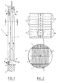
- Figure 1 shows a cross-sectional view of the first embodiment of a ventilation system according to the invention arranged in a facade.
- Figure 2 shows a cross-sectional view of the heat exchanger of the ventilation system of figure 1.
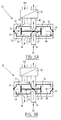
- Figures 3A and 3B show schematic view of a second embodiment of a ventilation system according to the invention.
- Figure 1 shows a ventilation system 1 arranged in a facade consisting of a wall 2 and a window frame 3.
- the ventilation system 1 comprises a fine wire heat exchanger 4.
- a fine wire heat exchanger 4 In figure 2 a cross section of this heat exchanger 4 is shown.
- the heat exchanger 4 has first channels 5 and second channels 6. Heat is exchanged between the first channels 5 and the second channels 6 by fine wires 7.
- a ventilator 9 is arranged, which sucks in the air AI.
- the air AI is then guided through the heat exchanger 4 and leaves the ventilation system through opening 10.
- Fresh outside air AO enters the heat exchanger through opening 11 into the second channels 6 in which it takes up the heat from the inside air AI.
- the heated fresh air AO is then blown out of the ventilation system 1 by a ventilator 12.
- the ventilators 8, 12 are controlled.
- the temperature of the inside air AI entering the heat exchanger is measured and the temperature, when the air leaves the heat exchanger 4.
- the temperature of the outside air AO entering the heat exchanger 4 is measured and the temperature of the outside AO when it leaves the heat exchanger.
- the temperature drop of the inside air AI should be the same as the temperature rise of the outside air AO. If this state is reached the fine wire heat exchanger 4 has the largest efficiency. This state can be reached by controlling both ventilators 8 and 12.
- FIGS 3A and 3B show a second embodiment of a ventilation system 20 according to the invention.
- the ventilation system 20 comprises a first double acting cylinder 21 with a piston 22.
- the piston defines the cylinder 21 into a first chamber 23 and a second chamber 24.
- the ventilation system 20 has furthermore a second double acting cylinder 25 with a piston 26.
- This piston defines the cylinder 25 into a third chamber 27 and a fourth chamber 28.
- Both pistons 22 and 26 are connected to each other.
- the four chambers 23, 24, 27 28 are connected to each through a series of tubing 29, 30 in which three valves 31, 32, 33 are arranged. In figure 3A the three valves 31, 32, 33 are in first position.
Landscapes
- Engineering & Computer Science (AREA)
- Mechanical Engineering (AREA)
- General Engineering & Computer Science (AREA)
- Chemical & Material Sciences (AREA)
- Combustion & Propulsion (AREA)
- Physics & Mathematics (AREA)
- Fluid Mechanics (AREA)
- Thermal Sciences (AREA)
- Ventilation (AREA)
- Heat-Exchange Devices With Radiators And Conduit Assemblies (AREA)
- Central Air Conditioning (AREA)
Claims (8)
- Belüftungssystem zum Austauschen der Luft (AI) in einem Raum mit Außenluft (AO), wobei das System (1) einen Feindrahtwärmetauscher (4) mit einem ersten Kanal (5) und einem zweiten Kanal (6) umfasst, dessen Kanäle (5, 6) in Wärmeaustauschverbindung miteinander stehen, und wobei der erste Kanal (5) einen mit der Außenluft (AO) verbundenen Einlass (11) und einen mit der Luft in dem Raum verbundenen Auslass aufweist, und wobei der zweite Kanal (6) einen mit der Luft (AI) in den Raum verbundenen Einlass (8) und einen mit der Außenluft verbundenen Auslass (10) aufweist,
gekennzeichnet durch,
Ausgleichsmittel zum Ausgleichen der Luftströme in den beiden Kanälen (5, 6) derart, dass die Wärmeübertragung maximiert ist. - Belüftungssystem (1) nach Anspruch 1, worin die Ausgleichsmittel umfassen- einen Ventilator (9), der in dem ersten Kanal (5) angeordnet ist,- einen Ventilator (12), der im zweiten Kanal (6) angeordnet ist,- zumindest vier Temperatursensoren, die in den Einlässen und Auslässen des ersten und zweiten Kanals angeordnet sind;- eine Steuereinheit zum Vergleichen von ausgelesenen Werten der Temperatursensoren und zum Kontrollieren der Ventilatoren in dem ersten und zweiten Kanal derart, dass der Temperaturunterschied zwischen dem Einlass und Auslass des ersten Kanals dem Temperaturunterschied zwischen dem Einlass und Auslass des zweiten Kanals entspricht.
- Belüftungssystem (20) nach Anspruch 1,
worin die Ausgleichsmittel umfassen:- einen ersten doppelt wirkenden Zylinder (21), wobei ein Kolben (22) eine erste Kammer (23) und eine zweite Kammer (24) begrenzt,- einen zweiten doppelt wirkenden Zylinder (25), wobei der Kolben eine dritte Kammer (27) und eine vierte Kammer (28) begrenzt, wobei der Kolben (22) des ersten Zylinders (21) mit dem Kolben (26) des zweiten Zylinders (25) derart verbunden ist, dass wenn die erste Kammer (23) durch Verschiebung der Kolben (22, 26) vergrößert wird, die dritte Kammer (27) ebenfalls vergrößert wird;- einen Ausgleichsmittel-Auslass und einen Ausgleichsmittel-Einlass;- Steuermittel zum wechselweise Verbinden des Ausgleichsmittel-Auslass mit entweder der ersten Kammer (23) oder der vierten Kammer (24), wobei der Ausgleichsmittel-Einlass mit entweder der zweiten Kammer (24) oder der dritten Kammer (27), der erste Kanal (5) mit entweder der vierten Kammer (28) oder der ersten Kammer (23), und der zweite Kanal (6) mit entweder der dritten Kammer (27) oder der zweiten Kammer (24). - Belüftungssystem (20) nach Anspruch 3,
wobei die Ausgleichsmittel zumindest einen Ventilator (34) umfassen, der in dem Ausgleichsmittel-Einlass, dem Ausgleichsmittel-Auslass, dem ersten Kanal (5) oder dem zweiten Kanal (6) angeordnet ist. - Belüftungssystem (20) nach Anspruch 3 oder 4,
umfassend Antriebsmittel, wie einen Linearmotor, zum Antreiben der Kolben (22, 26). - Belüftungssystem (1; 20) gemäß einem der vorangehenden Ansprüche, wobei die Hauptabmessungen des Wärmetauschers (4) kleiner als 0,55 m sind.
- Kombination einer Fassade, eines Raums, an der Innenseite und in der Nähe der Fassade und eines Belüftungssystems (1; 20) gemäß einem der vorhergehenden Ansprüche,
wobei der Einlass des ersten Kanals (5) des Systems (1; 20) mit Außenluft an der Außenseite der Fassade verbunden ist und der Auslass mit der Luft in dem Raum verbunden ist, und wobei der Einlass des zweiten Kanals (6) mit der Luft in dem Raum verbunden ist und der Auslass mit der Außenluft verbunden ist. - Anordnung nach Anspruch 8,
wobei das Belüftungssystem (1; 20) im Wesentlichen in der Fassade angeordnet ist.
Priority Applications (13)
| Application Number | Priority Date | Filing Date | Title |
|---|---|---|---|
| ES03076572T ES2280686T3 (es) | 2003-05-23 | 2003-05-23 | Sistema de ventilacion. |
| EP03076572A EP1479982B1 (de) | 2003-05-23 | 2003-05-23 | Belüftungseinrichtung |
| PT03076572T PT1479982E (pt) | 2003-05-23 | 2003-05-23 | Sistema de ventilação |
| DK03076572T DK1479982T3 (da) | 2003-05-23 | 2003-05-23 | Ventilationssystem |
| DE60311073T DE60311073T2 (de) | 2003-05-23 | 2003-05-23 | Belüftungseinrichtung |
| CA2525879A CA2525879C (en) | 2003-05-23 | 2004-05-19 | Ventilation system |
| PCT/EP2004/005496 WO2004104487A1 (en) | 2003-05-23 | 2004-05-19 | Ventilation system |
| US10/557,512 US7837127B2 (en) | 2003-05-23 | 2004-05-19 | Ventilation system |
| HK06109910.2A HK1087766B (en) | 2003-05-23 | 2004-05-19 | Ventilation system |
| CNB2004800140389A CN100436955C (zh) | 2003-05-23 | 2004-05-19 | 通风系统 |
| KR1020057022310A KR101103196B1 (ko) | 2003-05-23 | 2004-05-19 | 환기 시스템 |
| RU2005140294/06A RU2315917C2 (ru) | 2003-05-23 | 2004-05-19 | Система вентиляции и её комбинация с фасадом и внутренней частью комнаты, расположенной рядом с фасадом |
| JP2006529891A JP4422150B2 (ja) | 2003-05-23 | 2004-05-19 | 換気システム |
Applications Claiming Priority (1)
| Application Number | Priority Date | Filing Date | Title |
|---|---|---|---|
| EP03076572A EP1479982B1 (de) | 2003-05-23 | 2003-05-23 | Belüftungseinrichtung |
Publications (2)
| Publication Number | Publication Date |
|---|---|
| EP1479982A1 EP1479982A1 (de) | 2004-11-24 |
| EP1479982B1 true EP1479982B1 (de) | 2007-01-10 |
Family
ID=33041021
Family Applications (1)
| Application Number | Title | Priority Date | Filing Date |
|---|---|---|---|
| EP03076572A Expired - Lifetime EP1479982B1 (de) | 2003-05-23 | 2003-05-23 | Belüftungseinrichtung |
Country Status (12)
| Country | Link |
|---|---|
| US (1) | US7837127B2 (de) |
| EP (1) | EP1479982B1 (de) |
| JP (1) | JP4422150B2 (de) |
| KR (1) | KR101103196B1 (de) |
| CN (1) | CN100436955C (de) |
| CA (1) | CA2525879C (de) |
| DE (1) | DE60311073T2 (de) |
| DK (1) | DK1479982T3 (de) |
| ES (1) | ES2280686T3 (de) |
| PT (1) | PT1479982E (de) |
| RU (1) | RU2315917C2 (de) |
| WO (1) | WO2004104487A1 (de) |
Families Citing this family (20)
| Publication number | Priority date | Publication date | Assignee | Title |
|---|---|---|---|---|
| KR101253567B1 (ko) * | 2005-12-15 | 2013-04-11 | 삼성전자주식회사 | 환기 기능을 구비한 공기 조화 장치 및 그 제어방법 |
| JP4978303B2 (ja) * | 2007-05-15 | 2012-07-18 | パナソニック株式会社 | 熱交換形換気装置 |
| US20090104867A1 (en) * | 2007-10-22 | 2009-04-23 | Sherman John F | Building aperture mounted ventilation apparatus |
| DK2252846T3 (en) * | 2008-02-11 | 2017-07-17 | 3225335 Nova Scotia Ltd | Apparatus and method for storing and transporting living products from the water domain |
| US20100048123A1 (en) * | 2008-08-25 | 2010-02-25 | O'gorman Lawrence | System and method for energy efficient air cooling, exchange and circulation |
| KR101568706B1 (ko) * | 2009-05-29 | 2015-11-12 | 엘지전자 주식회사 | 공기조화기 |
| DE102009040107A1 (de) * | 2009-09-04 | 2011-03-10 | Ulrich Stieler Kunststoff Service E.K. | Vorrichtung zur Gebäudebelüftung |
| EP2354695A1 (de) * | 2009-12-29 | 2011-08-10 | SAVIO S.p.A. | Luftaustauschvorrichtung für Gebäude sowie Verfahren zur Steuerung besagter Vorrichtung |
| SI23299A (sl) * | 2010-02-23 | 2011-08-31 | Mik, D.O.O. | Prezračevalna naprava |
| US20120028560A1 (en) * | 2010-07-29 | 2012-02-02 | Zivota Nikolic | Fresh Air Recovery System |
| US20120083198A1 (en) * | 2010-10-01 | 2012-04-05 | Broan-NuTone Company , LLC | Fluid cleaning system and method |
| US8152608B1 (en) * | 2010-10-27 | 2012-04-10 | Aubrey Eugene Hamby | Solar energy intercept and waste heat recovery system |
| CA140478S (en) * | 2010-11-26 | 2011-11-30 | Josef Gartner Gmbh | Ventilation equipment |
| RU2568325C2 (ru) * | 2011-06-16 | 2015-11-20 | Абб Рисерч Лтд | Способ и система для управления потоком текучей среды в системе сети для текучей среды |
| US20140041830A1 (en) * | 2012-08-11 | 2014-02-13 | Architectural Applications P.C. | Heat and moisture transfer apparatus integrated into an exterior partition |
| US20140041833A1 (en) * | 2012-08-11 | 2014-02-13 | Architectural Applications P.C. | Flexible heat and moisture transfer system |
| US9795270B2 (en) | 2015-07-10 | 2017-10-24 | Tom Casale | Automatic freeze protection for dishwashers |
| CN109477657A (zh) | 2016-03-31 | 2019-03-15 | 工业设计实验室股份有限公司 | 紧凑型热回收通风系统 |
| IT201600084955A1 (it) * | 2016-08-12 | 2018-02-12 | Toone S A S Di Zanatta Marco & C | Gruppo di analisi e controllo della ventilazione di un ambiente interno o primo ambiente. |
| KR20220048523A (ko) | 2020-10-12 | 2022-04-20 | 씨디에스 주식회사 | 열교환형 환기시스템 |
Family Cites Families (13)
| Publication number | Priority date | Publication date | Assignee | Title |
|---|---|---|---|---|
| US4428197A (en) * | 1980-08-18 | 1984-01-31 | Liljequist Jon L | Stirling mechanical arrangements especially for double-acting pistons |
| AT388228B (de) * | 1986-03-04 | 1989-05-26 | Al Ko Kober Ges M B H | Vorrichtung zur belueftung von raeumen |
| SU1657886A1 (ru) * | 1989-04-11 | 1991-06-23 | Северо-Кавказский Территориальный Научно-Исследовательский И Проектный Институт Агропромышленного Комплекса | Устройство дл вентил ции помещений |
| NL9301439A (nl) * | 1993-08-19 | 1995-03-16 | Eleonoor Van Andel | Warmtewisselaar en werkwijze voor het vervaardigen daarvan. |
| JPH08159530A (ja) * | 1994-12-02 | 1996-06-21 | Ebara Corp | 全熱交換器 |
| JPH09184639A (ja) * | 1995-12-29 | 1997-07-15 | Daikin Ind Ltd | 空気調和機 |
| US6176305B1 (en) * | 1998-11-09 | 2001-01-23 | Building Performance Equipment Inc. | Ventilator system and method |
| ATE294363T1 (de) | 1999-02-03 | 2005-05-15 | Milan Nemcek | Öffnungsfüllung mit einer belüftungs- und schalldämpfungseinrichtung für räume |
| DE10010817A1 (de) * | 2000-03-08 | 2001-10-18 | Mig Mittelstands Entwicklungsg | Raumlüftungsvorrichtung |
| SE523865C2 (sv) * | 2000-05-02 | 2004-05-25 | Bengt Steneby | Ventilationsapparat för zonvis ventilation innefattande värmeväxlare för till- och frånluft samt sensorer för att bestämma luftflödenas relativa hastighetsavvikelse i resp kanal |
| JP2002156151A (ja) * | 2000-11-20 | 2002-05-31 | Toyox Co Ltd | 熱交換換気システム |
| US6789618B2 (en) * | 2001-09-05 | 2004-09-14 | Frederick J. Pearson | Energy recycling air handling system |
| DE20202538U1 (de) * | 2002-02-19 | 2002-04-25 | Schüco International KG, 33609 Bielefeld | Lüftungssystem |
-
2003
- 2003-05-23 DK DK03076572T patent/DK1479982T3/da active
- 2003-05-23 EP EP03076572A patent/EP1479982B1/de not_active Expired - Lifetime
- 2003-05-23 DE DE60311073T patent/DE60311073T2/de not_active Expired - Lifetime
- 2003-05-23 PT PT03076572T patent/PT1479982E/pt unknown
- 2003-05-23 ES ES03076572T patent/ES2280686T3/es not_active Expired - Lifetime
-
2004
- 2004-05-19 RU RU2005140294/06A patent/RU2315917C2/ru not_active IP Right Cessation
- 2004-05-19 WO PCT/EP2004/005496 patent/WO2004104487A1/en not_active Ceased
- 2004-05-19 CA CA2525879A patent/CA2525879C/en not_active Expired - Lifetime
- 2004-05-19 CN CNB2004800140389A patent/CN100436955C/zh not_active Expired - Fee Related
- 2004-05-19 US US10/557,512 patent/US7837127B2/en not_active Expired - Lifetime
- 2004-05-19 KR KR1020057022310A patent/KR101103196B1/ko not_active Expired - Fee Related
- 2004-05-19 JP JP2006529891A patent/JP4422150B2/ja not_active Expired - Fee Related
Also Published As
| Publication number | Publication date |
|---|---|
| ES2280686T3 (es) | 2007-09-16 |
| WO2004104487A1 (en) | 2004-12-02 |
| CA2525879A1 (en) | 2004-12-02 |
| US20070095523A1 (en) | 2007-05-03 |
| DE60311073T2 (de) | 2007-11-08 |
| KR101103196B1 (ko) | 2012-01-04 |
| DE60311073D1 (de) | 2007-02-22 |
| RU2005140294A (ru) | 2006-06-10 |
| EP1479982A1 (de) | 2004-11-24 |
| CA2525879C (en) | 2012-07-10 |
| CN100436955C (zh) | 2008-11-26 |
| HK1087766A1 (zh) | 2006-10-20 |
| JP4422150B2 (ja) | 2010-02-24 |
| US7837127B2 (en) | 2010-11-23 |
| DK1479982T3 (da) | 2007-05-21 |
| JP2007501375A (ja) | 2007-01-25 |
| PT1479982E (pt) | 2007-04-30 |
| KR20060028763A (ko) | 2006-04-03 |
| CN1795351A (zh) | 2006-06-28 |
| RU2315917C2 (ru) | 2008-01-27 |
Similar Documents
| Publication | Publication Date | Title |
|---|---|---|
| EP1479982B1 (de) | Belüftungseinrichtung | |
| US7238105B2 (en) | Dewpoint cooler designed as a frame or part thereof | |
| CN202338980U (zh) | 往复式热回收新风系统 | |
| CA2724494A1 (en) | Improvements in or relating to insulating panels | |
| WO2009147558A1 (en) | Regenerative decentralized alternating ventilation installation mit using hollow bricks of an outer wall | |
| CA3022931A1 (en) | Recuperator for exchanging energy between two air flows | |
| CN115095942B (zh) | 一种房间内设有卫生间的双向流全屋新风系统 | |
| CN211876227U (zh) | 一种外置窗式室内新风净化器 | |
| CN218915242U (zh) | 空调室内机比邻外墙设置的房间新风系统 | |
| KR100327305B1 (ko) | 주거용건물의조립식열회수환기시스템 | |
| GB2381855A (en) | Self contained air conditioning unit | |
| CN208566956U (zh) | 一种新风换气墙体 | |
| HK1087766B (en) | Ventilation system | |
| CN218915241U (zh) | 带有卫生间的房间新风系统 | |
| CN115095943B (zh) | 一种双向流全屋新风系统 | |
| CN116876707B (zh) | 一种可调节传热能力的装配式呼吸建筑外墙 | |
| KR100737323B1 (ko) | 폐열회수환기장치 | |
| JPH046336A (ja) | 換気装置 | |
| EP3420284B1 (de) | Ökologische anordnung zur verbesserung der energieeffizienz | |
| CN121498135A (zh) | 总进出风主机、新风空调主机、五恒系统及住宅能量中心 | |
| JPH024343Y2 (de) | ||
| CN115095944A (zh) | 一种风机盘管比邻外墙设置的全屋新风系统 | |
| JPH0960920A (ja) | 換気空調システム | |
| CN1609525A (zh) | 恒温空气交换机 |
Legal Events
| Date | Code | Title | Description |
|---|---|---|---|
| PUAI | Public reference made under article 153(3) epc to a published international application that has entered the european phase |
Free format text: ORIGINAL CODE: 0009012 |
|
| AK | Designated contracting states |
Kind code of ref document: A1 Designated state(s): AT BE BG CH CY CZ DE DK EE ES FI FR GB GR HU IE IT LI LU MC NL PT RO SE SI SK TR |
|
| AX | Request for extension of the european patent |
Extension state: AL LT LV MK |
|
| 17P | Request for examination filed |
Effective date: 20050413 |
|
| AKX | Designation fees paid |
Designated state(s): AT BE BG CH CY CZ DE DK EE ES FI FR GB GR HU IE IT LI LU MC NL PT RO SE SI SK TR |
|
| GRAP | Despatch of communication of intention to grant a patent |
Free format text: ORIGINAL CODE: EPIDOSNIGR1 |
|
| GRAS | Grant fee paid |
Free format text: ORIGINAL CODE: EPIDOSNIGR3 |
|
| GRAA | (expected) grant |
Free format text: ORIGINAL CODE: 0009210 |
|
| AK | Designated contracting states |
Kind code of ref document: B1 Designated state(s): AT BE BG CH CY CZ DE DK EE ES FI FR GB GR HU IE IT LI LU MC NL PT RO SE SI SK TR |
|
| PG25 | Lapsed in a contracting state [announced via postgrant information from national office to epo] |
Ref country code: SI Free format text: LAPSE BECAUSE OF FAILURE TO SUBMIT A TRANSLATION OF THE DESCRIPTION OR TO PAY THE FEE WITHIN THE PRESCRIBED TIME-LIMIT Effective date: 20070110 |
|
| REG | Reference to a national code |
Ref country code: GB Ref legal event code: FG4D |
|
| REG | Reference to a national code |
Ref country code: IE Ref legal event code: FG4D |
|
| REF | Corresponds to: |
Ref document number: 60311073 Country of ref document: DE Date of ref document: 20070222 Kind code of ref document: P |
|
| PG25 | Lapsed in a contracting state [announced via postgrant information from national office to epo] |
Ref country code: BG Free format text: LAPSE BECAUSE OF EXPIRATION OF PROTECTION Effective date: 20070411 |
|
| REG | Reference to a national code |
Ref country code: PT Ref legal event code: SC4A Free format text: AVAILABILITY OF NATIONAL TRANSLATION Effective date: 20070404 |
|
| REG | Reference to a national code |
Ref country code: SE Ref legal event code: TRGR |
|
| REG | Reference to a national code |
Ref country code: DK Ref legal event code: T3 |
|
| REG | Reference to a national code |
Ref country code: GR Ref legal event code: EP Ref document number: 20070401080 Country of ref document: GR |
|
| REG | Reference to a national code |
Ref country code: CH Ref legal event code: NV Representative=s name: AMMANN PATENTANWAELTE AG BERN |
|
| ET | Fr: translation filed | ||
| REG | Reference to a national code |
Ref country code: ES Ref legal event code: FG2A Ref document number: 2280686 Country of ref document: ES Kind code of ref document: T3 |
|
| PLBE | No opposition filed within time limit |
Free format text: ORIGINAL CODE: 0009261 |
|
| STAA | Information on the status of an ep patent application or granted ep patent |
Free format text: STATUS: NO OPPOSITION FILED WITHIN TIME LIMIT |
|
| PG25 | Lapsed in a contracting state [announced via postgrant information from national office to epo] |
Ref country code: SK Free format text: LAPSE BECAUSE OF FAILURE TO SUBMIT A TRANSLATION OF THE DESCRIPTION OR TO PAY THE FEE WITHIN THE PRESCRIBED TIME-LIMIT Effective date: 20070110 |
|
| 26N | No opposition filed |
Effective date: 20071011 |
|
| PG25 | Lapsed in a contracting state [announced via postgrant information from national office to epo] |
Ref country code: CZ Free format text: LAPSE BECAUSE OF FAILURE TO SUBMIT A TRANSLATION OF THE DESCRIPTION OR TO PAY THE FEE WITHIN THE PRESCRIBED TIME-LIMIT Effective date: 20070110 Ref country code: RO Free format text: LAPSE BECAUSE OF FAILURE TO SUBMIT A TRANSLATION OF THE DESCRIPTION OR TO PAY THE FEE WITHIN THE PRESCRIBED TIME-LIMIT Effective date: 20070110 |
|
| PG25 | Lapsed in a contracting state [announced via postgrant information from national office to epo] |
Ref country code: MC Free format text: LAPSE BECAUSE OF NON-PAYMENT OF DUE FEES Effective date: 20070531 |
|
| PG25 | Lapsed in a contracting state [announced via postgrant information from national office to epo] |
Ref country code: EE Free format text: LAPSE BECAUSE OF FAILURE TO SUBMIT A TRANSLATION OF THE DESCRIPTION OR TO PAY THE FEE WITHIN THE PRESCRIBED TIME-LIMIT Effective date: 20070110 |
|
| PG25 | Lapsed in a contracting state [announced via postgrant information from national office to epo] |
Ref country code: CY Free format text: LAPSE BECAUSE OF FAILURE TO SUBMIT A TRANSLATION OF THE DESCRIPTION OR TO PAY THE FEE WITHIN THE PRESCRIBED TIME-LIMIT Effective date: 20070110 |
|
| PG25 | Lapsed in a contracting state [announced via postgrant information from national office to epo] |
Ref country code: LU Free format text: LAPSE BECAUSE OF NON-PAYMENT OF DUE FEES Effective date: 20070523 |
|
| PG25 | Lapsed in a contracting state [announced via postgrant information from national office to epo] |
Ref country code: HU Free format text: LAPSE BECAUSE OF FAILURE TO SUBMIT A TRANSLATION OF THE DESCRIPTION OR TO PAY THE FEE WITHIN THE PRESCRIBED TIME-LIMIT Effective date: 20070711 |
|
| PGFP | Annual fee paid to national office [announced via postgrant information from national office to epo] |
Ref country code: PT Payment date: 20150427 Year of fee payment: 13 Ref country code: TR Payment date: 20150507 Year of fee payment: 13 |
|
| REG | Reference to a national code |
Ref country code: FR Ref legal event code: PLFP Year of fee payment: 14 |
|
| PG25 | Lapsed in a contracting state [announced via postgrant information from national office to epo] |
Ref country code: PT Free format text: LAPSE BECAUSE OF NON-PAYMENT OF DUE FEES Effective date: 20161123 |
|
| REG | Reference to a national code |
Ref country code: FR Ref legal event code: PLFP Year of fee payment: 15 |
|
| REG | Reference to a national code |
Ref country code: FR Ref legal event code: PLFP Year of fee payment: 16 |
|
| PGFP | Annual fee paid to national office [announced via postgrant information from national office to epo] |
Ref country code: FI Payment date: 20190531 Year of fee payment: 17 |
|
| PGFP | Annual fee paid to national office [announced via postgrant information from national office to epo] |
Ref country code: BE Payment date: 20190527 Year of fee payment: 17 Ref country code: GR Payment date: 20190530 Year of fee payment: 17 Ref country code: SE Payment date: 20190531 Year of fee payment: 17 Ref country code: FR Payment date: 20190527 Year of fee payment: 17 |
|
| PGFP | Annual fee paid to national office [announced via postgrant information from national office to epo] |
Ref country code: CH Payment date: 20190604 Year of fee payment: 17 |
|
| PGFP | Annual fee paid to national office [announced via postgrant information from national office to epo] |
Ref country code: AT Payment date: 20190521 Year of fee payment: 17 |
|
| PGFP | Annual fee paid to national office [announced via postgrant information from national office to epo] |
Ref country code: ES Payment date: 20191001 Year of fee payment: 17 |
|
| REG | Reference to a national code |
Ref country code: FI Ref legal event code: MAE |
|
| REG | Reference to a national code |
Ref country code: DK Ref legal event code: EBP Effective date: 20200531 |
|
| REG | Reference to a national code |
Ref country code: AT Ref legal event code: MM01 Ref document number: 351345 Country of ref document: AT Kind code of ref document: T Effective date: 20200523 |
|
| PG25 | Lapsed in a contracting state [announced via postgrant information from national office to epo] |
Ref country code: GR Free format text: LAPSE BECAUSE OF NON-PAYMENT OF DUE FEES Effective date: 20201209 Ref country code: SE Free format text: LAPSE BECAUSE OF NON-PAYMENT OF DUE FEES Effective date: 20200524 Ref country code: FI Free format text: LAPSE BECAUSE OF NON-PAYMENT OF DUE FEES Effective date: 20200523 Ref country code: CH Free format text: LAPSE BECAUSE OF NON-PAYMENT OF DUE FEES Effective date: 20200531 Ref country code: LI Free format text: LAPSE BECAUSE OF NON-PAYMENT OF DUE FEES Effective date: 20200531 Ref country code: AT Free format text: LAPSE BECAUSE OF NON-PAYMENT OF DUE FEES Effective date: 20200523 |
|
| REG | Reference to a national code |
Ref country code: BE Ref legal event code: MM Effective date: 20200531 |
|
| PG25 | Lapsed in a contracting state [announced via postgrant information from national office to epo] |
Ref country code: FR Free format text: LAPSE BECAUSE OF NON-PAYMENT OF DUE FEES Effective date: 20200531 Ref country code: DK Free format text: LAPSE BECAUSE OF NON-PAYMENT OF DUE FEES Effective date: 20200531 |
|
| PG25 | Lapsed in a contracting state [announced via postgrant information from national office to epo] |
Ref country code: BE Free format text: LAPSE BECAUSE OF NON-PAYMENT OF DUE FEES Effective date: 20200531 |
|
| PGFP | Annual fee paid to national office [announced via postgrant information from national office to epo] |
Ref country code: NL Payment date: 20210526 Year of fee payment: 19 |
|
| REG | Reference to a national code |
Ref country code: ES Ref legal event code: FD2A Effective date: 20211004 |
|
| PG25 | Lapsed in a contracting state [announced via postgrant information from national office to epo] |
Ref country code: IT Free format text: LAPSE BECAUSE OF NON-PAYMENT OF DUE FEES Effective date: 20200523 |
|
| PGFP | Annual fee paid to national office [announced via postgrant information from national office to epo] |
Ref country code: IE Payment date: 20210927 Year of fee payment: 19 |
|
| PG25 | Lapsed in a contracting state [announced via postgrant information from national office to epo] |
Ref country code: ES Free format text: LAPSE BECAUSE OF NON-PAYMENT OF DUE FEES Effective date: 20200524 |
|
| PGFP | Annual fee paid to national office [announced via postgrant information from national office to epo] |
Ref country code: GB Payment date: 20210927 Year of fee payment: 19 Ref country code: DE Payment date: 20210929 Year of fee payment: 19 |
|
| PG25 | Lapsed in a contracting state [announced via postgrant information from national office to epo] |
Ref country code: TR Free format text: LAPSE BECAUSE OF NON-PAYMENT OF DUE FEES Effective date: 20160523 |
|
| REG | Reference to a national code |
Ref country code: DE Ref legal event code: R119 Ref document number: 60311073 Country of ref document: DE |
|
| REG | Reference to a national code |
Ref country code: NL Ref legal event code: MM Effective date: 20220601 |
|
| GBPC | Gb: european patent ceased through non-payment of renewal fee |
Effective date: 20220523 |
|
| PG25 | Lapsed in a contracting state [announced via postgrant information from national office to epo] |
Ref country code: IE Free format text: LAPSE BECAUSE OF NON-PAYMENT OF DUE FEES Effective date: 20220523 |
|
| PG25 | Lapsed in a contracting state [announced via postgrant information from national office to epo] |
Ref country code: GB Free format text: LAPSE BECAUSE OF NON-PAYMENT OF DUE FEES Effective date: 20220523 Ref country code: DE Free format text: LAPSE BECAUSE OF NON-PAYMENT OF DUE FEES Effective date: 20221201 |
|
| PG25 | Lapsed in a contracting state [announced via postgrant information from national office to epo] |
Ref country code: NL Free format text: LAPSE BECAUSE OF NON-PAYMENT OF DUE FEES Effective date: 20220601 |