EP1478552B1 - Unterfahrschutz für fahrzeuge - Google Patents
Unterfahrschutz für fahrzeuge Download PDFInfo
- Publication number
- EP1478552B1 EP1478552B1 EP03713125A EP03713125A EP1478552B1 EP 1478552 B1 EP1478552 B1 EP 1478552B1 EP 03713125 A EP03713125 A EP 03713125A EP 03713125 A EP03713125 A EP 03713125A EP 1478552 B1 EP1478552 B1 EP 1478552B1
- Authority
- EP
- European Patent Office
- Prior art keywords
- box
- folded
- platform
- underrun protection
- sheet unit
- Prior art date
- Legal status (The legal status is an assumption and is not a legal conclusion. Google has not performed a legal analysis and makes no representation as to the accuracy of the status listed.)
- Expired - Lifetime
Links
- 230000004224 protection Effects 0.000 title claims description 35
- 238000007789 sealing Methods 0.000 claims description 6
- 230000002093 peripheral effect Effects 0.000 abstract 2
- 230000008878 coupling Effects 0.000 description 3
- 238000010168 coupling process Methods 0.000 description 3
- 238000005859 coupling reaction Methods 0.000 description 3
- 229920005372 Plexiglas® Polymers 0.000 description 2
- 210000005069 ears Anatomy 0.000 description 2
- 238000010276 construction Methods 0.000 description 1
- 230000006378 damage Effects 0.000 description 1
- 230000001419 dependent effect Effects 0.000 description 1
- 235000000396 iron Nutrition 0.000 description 1
- 230000004048 modification Effects 0.000 description 1
- 238000012986 modification Methods 0.000 description 1
- 239000002985 plastic film Substances 0.000 description 1
- 229920006255 plastic film Polymers 0.000 description 1
Images


Classifications
-
- B—PERFORMING OPERATIONS; TRANSPORTING
- B60—VEHICLES IN GENERAL
- B60R—VEHICLES, VEHICLE FITTINGS, OR VEHICLE PARTS, NOT OTHERWISE PROVIDED FOR
- B60R19/00—Wheel guards; Radiator guards, e.g. grilles; Obstruction removers; Fittings damping bouncing force in collisions
- B60R19/56—Fittings damping bouncing force in truck collisions, e.g. bumpers; Arrangements on high-riding vehicles, e.g. lorries, for preventing vehicles or objects from running thereunder
- B60R19/565—Fittings damping bouncing force in truck collisions, e.g. bumpers; Arrangements on high-riding vehicles, e.g. lorries, for preventing vehicles or objects from running thereunder on vehicle sides
-
- B—PERFORMING OPERATIONS; TRANSPORTING
- B60—VEHICLES IN GENERAL
- B60R—VEHICLES, VEHICLE FITTINGS, OR VEHICLE PARTS, NOT OTHERWISE PROVIDED FOR
- B60R13/00—Elements for body-finishing, identifying, or decorating; Arrangements or adaptations for advertising purposes
Definitions
- This invention relates to an underrun protection for vehicles of the type that includes a wheel-carried chassis having a platform or the like, the underrun protection comprising a stiff sheet unit fastenable on the vehicle having the purpose of partly covering the free space under the platform, thereby counteracting running-in under the platform by other vehicles, the sheet unit comprising on one hand a first box, which is composed of a bottom wall and a border located along the periphery thereof, and which is articulatedly connected to at least one fastening unit mountable on the vehicle in order to be able to be turned between a folded-down, underrun-protecting position, and a folded-out position in which the space under the platform is made accessible, and on the other hand a second box for enclosing an information carrier and which comprises a transparent sheet and a frame surrounding the same, said frame being articulatedly connected to the border of the first box in order to be turned between a folded-in position in the first box and a folded-out position in which the information carrier is exchangeable.
- the vehicles may be provided with particular underrun protections that essentially extend in flush with the long sides of the platform or addition in order to cover most of the space between the front and rear wheels.
- underrun protections are permanently immovably fixed in relation to the vehicle chassis, more precisely by the covering sheet unit being stiffly united to a fastening unit, which is in turn stiffly connected to the chassis, e.g. by means of welded or bolt joints.
- the fact that the underrun protection is fixed in a given position makes it difficult or impossible to practically utilize the storage box or storage boxes that usually are mounted on the chassis in the area immediately under the platform.
- Another shortcoming of the known underrun protections is that the same are not suitable for exposing commercial and/or information messages, in spite of the fact that the same are well visible, for instance from the side of the vehicle.
- a primary object of the invention is to provide an underrun protection that on one hand enables simple and convenient access to such storage boxes that according to the standard practice are found on the frame works of, for instance, lorries and on the other hand is suitable for clear exposure of information messages.
- Another object of the invention is to provide an underrun protection that permits exchange of the desired information or commercial messages in a fast and convenient way. Furthermore, said message should be possible to illuminate with the purpose of making the same extraordinarily well visible.
- Generic DE-A-43 17 391 discloses an underrun protection for vehicles.
- Said underrun protection comprises a stiff sheet unit fastenable on the vehicle and which has the purpose of partly covering the free space under the vehicle.
- the sheet unit comprises a first board having a bottom wall and a second board for enclosing an information carrier.
- the second board comprises a transparent sheet and is articulately connected to the first board in order to be turned between a folded in position and a folded out position in which the carrier is exchangeable.
- EP-A-0 857 620 discloses an underrun protection for vehicles. Said underrun protection is articulately connected to the vehicle in order to be turned between a folded down, underrun protecting position, and a folded out position in which the space under the vehicle is made accessible.
- a vehicle in the form of a lorry having a chassis 1 being carried by front and rear wheel sets 2 and 3, respectively.
- a platform 4 or a house-like addition is mounted on the chassis, which is illustrated in the form of two channel irons in figs 3 and 4, a platform 4 or a house-like addition is mounted.
- the detail 4 in figs 3 and 4 may consist of a bottom to the vehicle addition, the concept "platform” will henceforth be used exclusively, for the sake of simplicity.
- a part of the platform protrudes laterally from the chassis 1, the outer long side edge of the platform being situated approximately in flush with the outside of outer wheels in the rear wheel set of the vehicle.
- an underrun protection in its entirety designated 5, is arranged in the space between the front and the rear wheel sets 2, 3.
- the same includes on one hand a sheet unit, in its entirety designated 6 (see fig 2), and on the other hand two fastening units 7 that are mountable onto the vehicle, more precisely underneath the platform 4.
- the sheet unit 6 is carried by two spaced-apart fastening units that are located near the front and rear short ends of the sheet unit.
- the individual fastening unit 7 includes a crossbar 8 extending transverse to the plane of the sheet unit, which crossbar is permanently attached in a given position underneath the platform 4, e.g. by means of a bolted or welded joint (not shown).
- the crossbar 8 consists of a first box profile into which a second, thinner box profile 9 is inserted. Said second box profile 9 is displaceably movable inside the first box profile 8 and lockable in different positions in relation to the same, e.g. by means of one or more bolts 10 insertable in selected holes in a series of holes 11 in the box profile 8.
- the box profile 9 has a main hinge 12 around which the sheet unit 6 is turnable.
- Said main hinge may advantageously consist of a robust dowel mounted in a bushing.
- a guide 13 is arranged for each fastening unit, e.g. in the form of a flange-provided channel bar.
- an arm 14 to which the main hinge 12 is connected, is inserted, and which is adjustable and lockable in different axial positions in the guide. Locking of the arm in relation to the guide may be carried out by means of one or more bolts or pins 15.
- the sheet unit 6 may be set in different level positions in relation to the fastening unit 7 and platform 4, respectively.
- a fixed shoulder 16 is applied, against which the arm 14 is pressable in order to be located perpendicularly to said box profile.
- the lower flange of the box profile 9 is partly cut off in order to house the upper end of the arm 14.
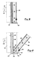
- the main hinge 12 permits turning of the sheet unit in the direction outwards/upwards to the laterally folded-out state that is shown in fig 4.
- the arm 14 is stopped in a vertically pendent position by means of the stop shoulder 16.
- a diagonal bracing 17 serving as a push rod extends, the inner end of which is connected to an ear 19 on the bottom side of the box profile 8 via a hinge 18, while the opposite end is connected to an ear 21 on the inner side of the guide profile 13 via a second hinge 20.
- the hinge 20 is in the form of a quick-action lock, e.g. in the form of a pin, which is insertable in a key hole-like opening 22 in the ear (see fig 5).
- the ear 21 is located near the lower end of the guide profile 13, i.e. near the lower edge of the sheet unit 6, while the ear 19 is located in the immediate vicinity of the inner end of the box profile 8.
- the diagonal bracing 17 obtains a maximum length in order to be able to absorb great forces that are applied to the sheet unit from outside.
- the diagonal bracing 17 includes two parts, adjustably movable in relation to each other, in the form of telescopic tubes 23, 23' that may be locked in a desired position in relation to each other by means of a locking screw 24 or the like.
- the length of the diagonal bracing may be adapted to different mounting positions for the sheet unit. Said mounting positions depend on how much the slender box profiles 9 are protruded from the box profiles 8 as well as how far the arms 14 are put into the guide profiles 13.
- a gas spring 25 acts with the purpose of at least facilitating turning of the sheet unit 6 in the direction outwards/upwards.
- Each such gas spring 25 is connected to the sides of the profiles 9, 13 via pivot pins.
- a slot 26 is recessed, into which the upper hinge of the gas spring may be inserted if the box profile 9 is to be inserted far into in the box profile 8.
- the underrun protection according to the invention also may be manufactured having one single predetermined mounting position for the sheet unit 6.
- the pendent arm 14 may be in direct connection with the back side of the sheet unit 6, and the fastening unit 7 made from one single girder or section.
- the sheet unit is composed of two mutually turnable boxes 27, 28, the first-mentioned one of which includes a bottom or inner wall 29, along the periphery of which a border 30 extends, which forms a rectangular frame that is outwardly open.
- the other box 28 includes a rectangular frame 31 in the form of an L-section having a gable flange 32 and a front flange 33.
- Said front flange 33 is comparatively slender and has in the example a width that is smaller than the width of the gable flange 32.
- a transparent sheet 34 is mounted, which is kept in place in the open space between the front flanges 33 of the box by means of semi-rigid, sealings 35.
- Said sealings 35 which may consist of rubber or the like, guarantee that moisture does not get into the interior of the sheet unit.
- a circumfering sealing 36 is arranged at the inner edge of the gable flanges 32 of the frame 31 at the inner edge of the gable flanges 32 of the frame 31 . It should in particular be observed that said sealing 36 extends solely along the inner edges of the flanges 32 and that the interior of the box 28 opens rearwards (against the bottom wall 29 of the box 27).
- An information or advertising carrier 37 for instance consisting of a sheet of board or paper or of a plastic film of a suitable thickness, may be applied against the bottom wall 29.
- a message of the type that is outlined at 38 in fig 1 is printed or applied in another way.
- a second transparent sheet 39 is arranged, e.g. in the form of a sheet of PLEXIGLAS®.
- the outer corner of the frame 31 in the box 28 is connected to the outer edge of the lower border of the border piece 30 via a hinge 40.
- the box 28 may be turned between on one hand a fully folded-in position in the box 27 according to fig 5, and a folded-out position according to fig 6.
- the box 28 should be possible to turn at least 180°, suitably 270°, in relation to the box 27.
- the two box profiles 8 are initially fixed to the bottom side of the platform 4, and then the box profiles 9 are inserted so far into the box profiles 8 that the sheet unit 6 will hang down approximately in flush with the long side edge of the platform 4 (see fig 3).
- the box profiles 9 are fixed by means of the mounting bolts 10 (or screws).
- the sheet unit 6 is adjusted to the desired level by the fact that the guide profiles 13 are brought to the desired position along the arms 14, and then fixing is carried out by means of the mounting bolts 15 (or screws).
- the outer ends of the diagonal bracings 17 are connected to the ears 21 positioned furthest down on the guide profiles 13.
- the telescopic tube 23' is still displaceable in relation to the telescopic tube 23.
- the telescopic tube 23 is, however, fixed by tightening of the locking screw 24, whereby the length of the diagonal bracing is finally settled.
- the hinge 18 is permanently connected to the ear 19.
- the sheet unit covers a large part of the free space between the platform 4 and the ground under the vehicle, whereby running-in under the platform is counteracted.
- a storage box 41 is found on the vehicle according to the standard practice, shown by means of dash-dotted lines. Said box is located on the outside of the chassis 1 and near the bottom side of the platform. As is seen in fig 3, the storage box is extraordinarily difficult to reach when the sheet unit 6 of the underrun protection is fixed in the vertically pendent position thereof.
- the sheet unit 6 is folded out to the position illustrated in fig 4. This may be effected by the simple measure of releasing the quick coupling keys 20 and bringing the sheet to turn outwards/upwards. Such a folding-out may be effected either by means of solely the gas springs 25, if the same are sufficiently powerful, or by a combination of the action of the gas springs and manual lifting of the sheet unit.
- the sheet unit is again folded down to the vertical, active state thereof.
- the stop shoulder 16 ensures that the sheet unit is located in an exact vertical position, which implies that the ear 21 is immediately located in the correct position for receipt of the quick coupling key 20 when the diagonal bracing 17 is to be connected to the sheet unit 6 again.
- the box 28 is folded out of the box 27, and then the sheet 39 and the proper advertising carrier 37 is removed from the interior of the box 27.
- the box may 28 be folded out at different angles in relation to the box 27, e.g. 180° or 270°.
- the box 27 may either remain in the vertical position thereof, or be folded out to the horizontal position shown in fig 4.
- a new advertising carrier 37 is inserted along with a covering PLEXIGLAS® sheet 39, and then the box 28 is again folded into the box 27.
- exchange of advertising or information carrier may be effected in a fast and convenient way.
- the box 28 has lamps 42 in the interior thereof, e.g. light emitting diodes, in order to light up the interior of the box, thereby in a marked way making the message on the advertising carrier 37 clear.
- said lamps 42 are arranged comparatively close to each other at the inside of the frame 31 and directed inwards towards the centre of the box 28.
- An important advantage of the invention is that access to storage boxes or other parts occurring on the chassis is not obstructed by the presence of the underrun protection on the vehicle.
- Another advantage is that the underrun protection in an effective way may be utilized in order to expose an information or commercial message, a particular advantage being the fact that exchange of the information carrier may be carried out in a fast, simple and convenient way.
- the underrun protection may in a particularly simple and inexpensive version be manufactured without the possibility of adjusting the sheet unit to different positions laterally and vertically, respectively. It is also feasible to spare the gas springs, the sheet being manipulated in solely the manual way.
Landscapes
- Engineering & Computer Science (AREA)
- Mechanical Engineering (AREA)
- Body Structure For Vehicles (AREA)
- Compositions Of Macromolecular Compounds (AREA)
- Treatment And Processing Of Natural Fur Or Leather (AREA)
- Train Traffic Observation, Control, And Security (AREA)
- Handcart (AREA)
- Tents Or Canopies (AREA)
- Motorcycle And Bicycle Frame (AREA)
- Vehicle Waterproofing, Decoration, And Sanitation Devices (AREA)
Claims (7)
- Unterfahrschutz für Fahrzeuge des Typs, der ein Räder-getragenes Fahrgestell (1) mit einer Plattform (4) oder dergleichen aufweist, umfassend ein steifes Plattenteil (6), das an dem Fahrzeug befestigbar ist und das den Zweck besitzt, den freien Raum unter der Plattform (4) teilweise abzudecken, um einem Einfahren unter die Plattform durch andere Fahrzeuge entgegenzuwirken, wobei das Plattenteil (6) einerseits eine erste Box (27) umfasst, die aus einer Bodenwand (29) und einer entlang der Peripherie davon befindlichen Umrandung (30) zusammengesetzt ist, und die gelenkig mit mindestens einem Befestigungsteil (7) verbunden ist, das an dem Fahrzeug montierbar ist, um zwischen einer heruntergeklappten Unterfahrschutz-Position und einer ausgeklappten Position, in der der Raum unter Plattform (4) zugänglich ist, gedreht zu werden, und andererseits eine zweite Box (28) zum Umhüllen eines Informationsträgers (37), die eine transparente Folie (34) und einen diese umgebenden Rahmen (31) umfasst, wobei der Rahmen mit der Umrandung (30) der ersten Box gelenkig verbunden ist, um zwischen einer eingeklappten Position in der ersten Box (27) und einer ausgeklappten Position, in der der Informationsträger (37) austauschbar ist, gedreht zu werden, dadurch gekennzeichnet, dass die zweite Box (28) des Plattenteils (6) nach innen offen ist und mit einer peripheren Dichtung (36) versehen ist, die so angeordnet ist, dass sie gegen die transparente Folie (39) an der Außenseite des Informationsträgers (37) sowie gegen die Innenseite der Umrandung (30) der ersten Box (27) abdichtend gepresst wird.
- Unterfahrschutz nach Anspruch 1, dadurch gekennzeichnet, dass er zwei beabstandete Befestigungsteile (7) umfasst, von denen jedes individuell einen Querrahmen (8) aufweist, der an der Bodenseite der Plattform (4) befestigbar ist, und mit dem ein Ende einer Diagonalstrebe (17) gelenkig verbunden ist, deren gegenüberliegendes Ende direkt oder indirekt lösbar mit dem Bodenteil der ersten Box (27) verbunden ist.
- Unterfahrschutz nach Anspruch 2, dadurch gekennzeichnet, dass zwischen der Querschiene und der ersten Box (27) eine Gasfeder (25) wirkt, die immer darauf abzielt, die Box nach außen gegen die herausgeklappte Position zu drehen.
- Unterfahrschutz nach Anspruch 2 oder 3, dadurch gekennzeichnet, dass der Querrahmen einerseits ein erstes Boxenprofil (8) aufweist, das permanent an die Bodenseite der Plattform (4) befestigbar ist, und andererseits ein schmaleres zweites Boxenprofil (9), das verschiebbar in das erste Boxenprofil eingeführt ist und in den gewünschten axialen Positionen in Relation dazu arretierbar ist.
- Unterfahrschutz nach Anspruch 4, dadurch gekennzeichnet, dass das zweite Boxenprofil (9) an einem freien Ende mit einem Arm (14) über ein Hauptgelenk (12) verbunden ist, und das Plattenteil in verschiedenen Positionen in Relation zum Arm einstellbar und arretierbar ist.
- Unterfahrschutz nach Anspruch 5, dadurch gekennzeichnet, dass eine Anschlagschulter (16) an der Unterseite des Boxenprofils (9) angeordnet ist, wobei die Schulter verhindert, dass das Plattenteil aus der vertikalen Position nach innen gedreht wird.
- Unterfahrschutz nach einem der vorhergehenden Auprüche, dadurch gekennzeichnet, dass Lampen (42) innerhalb der zweiten Box (28) angeordnet sind, um das Innere des Plattenteils zu beleuchten.
Applications Claiming Priority (3)
| Application Number | Priority Date | Filing Date | Title |
|---|---|---|---|
| SE0200616A SE521178C2 (sv) | 2002-02-28 | 2002-02-28 | Underkörningsskydd för landsvägsfordon |
| SE0200616 | 2002-02-28 | ||
| PCT/SE2003/000320 WO2003093066A1 (en) | 2002-02-28 | 2003-02-26 | Underrun protection for vehicles |
Publications (2)
| Publication Number | Publication Date |
|---|---|
| EP1478552A1 EP1478552A1 (de) | 2004-11-24 |
| EP1478552B1 true EP1478552B1 (de) | 2006-07-19 |
Family
ID=20287124
Family Applications (1)
| Application Number | Title | Priority Date | Filing Date |
|---|---|---|---|
| EP03713125A Expired - Lifetime EP1478552B1 (de) | 2002-02-28 | 2003-02-26 | Unterfahrschutz für fahrzeuge |
Country Status (7)
| Country | Link |
|---|---|
| US (1) | US7188875B2 (de) |
| EP (1) | EP1478552B1 (de) |
| AT (1) | ATE333395T1 (de) |
| AU (1) | AU2003220783A1 (de) |
| DE (1) | DE60306899T2 (de) |
| SE (1) | SE521178C2 (de) |
| WO (1) | WO2003093066A1 (de) |
Families Citing this family (45)
| Publication number | Priority date | Publication date | Assignee | Title |
|---|---|---|---|---|
| SE527825C2 (sv) * | 2004-05-27 | 2006-06-13 | Volvo Lastvagnar Ab | Anordning vid ett sidoskydd för fordon, samt ett fordon försett med ett sådant sidoskydd |
| US7077440B1 (en) * | 2004-10-08 | 2006-07-18 | Armindo Morales | Knockdown nerf bar for replaceably and adjustably protecting a side of a vehicle from dings and dents |
| US20070228748A1 (en) * | 2006-03-30 | 2007-10-04 | Ford Global Technologies, Llc | Supplemental side impact protection system for automotive vehicle |
| WO2007115572A1 (en) * | 2006-04-07 | 2007-10-18 | Jan Erik Krusaa | Safety shield for a vehicle |
| US7789453B2 (en) * | 2007-05-30 | 2010-09-07 | Vanguard National Trailer Corporation | Trailer keel |
| US7780224B2 (en) * | 2007-06-08 | 2010-08-24 | Vanguard National Trailer Corporation | Crash attenuating underride guard |
| ATE469006T1 (de) * | 2008-04-29 | 2010-06-15 | C R F Societ Consortile Per Az | Seitenaufprallschutzvorrichtung für industriefahrzeuge, insbesondere für anhänger |
| CA3038385C (en) | 2009-04-16 | 2021-03-02 | Wabash National, L.P. | Side skirt and side underride cable system for a trailer |
| US8505943B2 (en) * | 2009-07-27 | 2013-08-13 | Public Transportation Safety Int'l Corp. | Cantilevered, vehicle side mount safety guard |
| US8567802B2 (en) * | 2009-07-27 | 2013-10-29 | Public Transportation Safety Int'l Corp. | Cantilevered, vehicle side mount safety guard |
| US8146702B2 (en) * | 2009-09-10 | 2012-04-03 | Jervis B. Webb Company | Load handling bumper for material handling device |
| US8317239B2 (en) * | 2010-04-22 | 2012-11-27 | Four State International Trucks, Inc. | Flip-up bumper assembly |
| CA2762860C (en) * | 2011-02-18 | 2019-03-12 | Laydon Composites Ltd. | Clamp assembly for mounting panels to i-beams |
| US9676367B2 (en) | 2011-05-09 | 2017-06-13 | Public Transportation Safety International Corp. | Telescoping vehicle safety guard |
| CN102490677A (zh) * | 2011-12-19 | 2012-06-13 | 袁玉君 | 一种汽车安全防护系统 |
| US8783758B2 (en) | 2012-03-21 | 2014-07-22 | Wabash National, L.P. | Folding side skirt system for a trailer |
| USD709806S1 (en) * | 2013-04-21 | 2014-07-29 | Herbert Musgrove | Portable bumper guard |
| US9919750B2 (en) | 2013-08-15 | 2018-03-20 | Wabash National, L.P. | Side skirt system for reducing drag |
| CA2884510C (en) | 2014-03-11 | 2022-01-04 | Wabash National, L.P. | Side skirt system for a trailer |
| US20150291116A1 (en) * | 2014-04-14 | 2015-10-15 | Konrad David Pi | Deployable side protector for vehicles |
| US9352714B2 (en) | 2014-10-09 | 2016-05-31 | Stephen Allen Batzer | Adjustable side under-ride guard for sliding axle trailer |
| US9463759B1 (en) | 2014-10-29 | 2016-10-11 | Aaron J. Kiefer | Underride guards |
| US9688320B2 (en) | 2014-10-29 | 2017-06-27 | Wabash National, L.P. | Side skirt system for a trailer |
| US9487171B2 (en) | 2015-01-16 | 2016-11-08 | Patrick Keith Rogers | Telescoping side under-ride guard for sliding axle trailer |
| US9783144B2 (en) | 2015-08-18 | 2017-10-10 | Sti Holdings, Inc. | Trailer with rear impact guard |
| EP3362323B1 (de) | 2015-10-15 | 2021-03-24 | Public Transportation Safety International Corp. | Teleskopierbarer fahrzeugsicherheitsschutz |
| US10005628B2 (en) | 2015-10-23 | 2018-06-26 | Liftgate Lok Inc. | Loading dock locking system |
| US9764781B2 (en) * | 2016-02-03 | 2017-09-19 | Paccar Inc | Self-stowing rectangular pontoon trailer skirts |
| US10118585B2 (en) | 2016-08-25 | 2018-11-06 | Public Transportation Safety Int'l. Corp. | Vehicle safety guard |
| US10343731B2 (en) | 2016-09-30 | 2019-07-09 | Wabash National, L.P. | Skirt system mount bracket assembly |
| US10369949B2 (en) | 2017-02-27 | 2019-08-06 | Sti Holdings, Inc. | Rear impact guard |
| US9994267B1 (en) * | 2017-04-12 | 2018-06-12 | GM Global Technology Operations LLC | Active side-skirts for a motor vehicle |
| US10549797B2 (en) | 2017-04-20 | 2020-02-04 | Wabash National, L.P. | Side underride guard |
| MX2022012587A (es) | 2017-09-13 | 2022-11-09 | Wabash National Lp | Proteccion antiempotramiento lateral. |
| US10940817B2 (en) | 2018-02-21 | 2021-03-09 | Wabash National, L.P. | Side underride guard |
| US10857961B2 (en) | 2018-05-23 | 2020-12-08 | Hydro Extrusion USA, LLC | Mounting system for truck underride protection |
| FR3090560B1 (fr) * | 2018-12-21 | 2022-05-27 | Jean Chereau Sas | Carrosserie de véhicule routier de transport de marchandises munie de carénages latéraux |
| WO2021062104A1 (en) * | 2019-09-25 | 2021-04-01 | Ic Innovations Llc | Roadway debris clearing system |
| IT202000005656A1 (it) * | 2020-03-17 | 2021-09-17 | Reco S R L | Dispositivo di protezione laterale per veicoli stradali pesanti e veicolo incorporante lo stesso |
| US11738704B2 (en) | 2020-04-02 | 2023-08-29 | Great Dane Llc | Underride guard assembly for trailers |
| CN113978406B (zh) * | 2021-12-15 | 2022-08-23 | 沛县迅驰专用车辆制造有限公司 | 一种半挂车用缓冲侧板 |
| CN115027399B (zh) * | 2022-06-17 | 2024-07-26 | 安徽鑫氟隆化工设备有限公司 | 一种粉罐车用的侧防护机构 |
| CN115027579B (zh) * | 2022-07-15 | 2024-08-02 | 王冰 | 一种货车侧翻时的车厢保护装置 |
| US12024119B2 (en) * | 2022-11-08 | 2024-07-02 | Gayle Croley | Theft barrier assembly |
| US12145520B1 (en) | 2023-09-26 | 2024-11-19 | Sti Holdings, Inc. | Side impact guard |
Family Cites Families (12)
| Publication number | Priority date | Publication date | Assignee | Title |
|---|---|---|---|---|
| DE2634880A1 (de) | 1975-08-21 | 1978-02-09 | Maschf Augsburg Nuernberg Ag | Lastkraftwagen mit vermindertem luftwiderstand |
| US4217715A (en) * | 1979-02-08 | 1980-08-19 | Bryan William G Jr | Side protector for vehicles |
| US4247138A (en) * | 1979-04-06 | 1981-01-27 | Quinton Hazell Limited | Shock absorbing apparatus for vehicles |
| US4688824A (en) * | 1986-03-04 | 1987-08-25 | Herring John D | Safety device for vehicles |
| DE9116092U1 (de) | 1991-12-24 | 1992-02-27 | Hofmeister & Meincke GmbH & Co., 2800 Bremen | Seitlicher Unterfahrschutz für Lastkraftwagen, Zugmaschinen und dergleichen |
| DE4324803A1 (de) | 1992-09-08 | 1994-03-10 | Haas Fahrzeugbau Gmbh | Unterfahrschutz-Vorrichtung für Lastkraftwagen |
| DE4317391A1 (de) | 1993-05-25 | 1994-12-01 | Marita Klix | Kombinierter Kraftfahrzeugwerbeträger/Unterfahrschutz |
| US5673953A (en) * | 1996-09-13 | 1997-10-07 | Spease; Donald R. | Breakaway ICC bumper |
| NL1004967C1 (nl) * | 1997-01-10 | 1998-07-13 | Transplus Components | Zijdelingse afscherming ten behoeve van een voertuig, een daarmee uitgerust voertuig alsmede enig onderdeel voor toepassing in voornoemde afscherming. |
| US6764116B2 (en) * | 2002-01-18 | 2004-07-20 | Transfreight Technology, Llc | Adjustable safety bumper |
| US6760986B1 (en) * | 2002-05-17 | 2004-07-13 | Macneil David F. | Vehicle license plate cover |
| US6764118B2 (en) * | 2002-09-11 | 2004-07-20 | Autoliv Asp, Inc. | Active bumper assembly |
-
2002
- 2002-02-28 SE SE0200616A patent/SE521178C2/sv not_active IP Right Cessation
-
2003
- 2003-02-26 US US10/505,675 patent/US7188875B2/en not_active Expired - Fee Related
- 2003-02-26 AU AU2003220783A patent/AU2003220783A1/en not_active Abandoned
- 2003-02-26 AT AT03713125T patent/ATE333395T1/de not_active IP Right Cessation
- 2003-02-26 EP EP03713125A patent/EP1478552B1/de not_active Expired - Lifetime
- 2003-02-26 WO PCT/SE2003/000320 patent/WO2003093066A1/en not_active Ceased
- 2003-02-26 DE DE60306899T patent/DE60306899T2/de not_active Expired - Lifetime
Also Published As
| Publication number | Publication date |
|---|---|
| US20050104390A1 (en) | 2005-05-19 |
| ATE333395T1 (de) | 2006-08-15 |
| DE60306899D1 (de) | 2006-08-31 |
| SE0200616L (sv) | 2003-08-29 |
| SE521178C2 (sv) | 2003-10-07 |
| SE0200616D0 (sv) | 2002-02-28 |
| WO2003093066A1 (en) | 2003-11-13 |
| EP1478552A1 (de) | 2004-11-24 |
| AU2003220783A1 (en) | 2003-11-17 |
| US7188875B2 (en) | 2007-03-13 |
| DE60306899T2 (de) | 2007-02-22 |
Similar Documents
| Publication | Publication Date | Title |
|---|---|---|
| EP1478552B1 (de) | Unterfahrschutz für fahrzeuge | |
| US4750753A (en) | Bumper mounted folding step assembly | |
| US4786073A (en) | Foldable trailer | |
| US6467417B1 (en) | Vehicle table | |
| US3871695A (en) | Folding truck bumper | |
| US5772271A (en) | Versatile, multipurpose truck body | |
| US5375773A (en) | Salt spreader mounting assembly | |
| CA2199300A1 (en) | Highway crash cushion | |
| EP0810123B1 (de) | Rammschutzeinheit für Kraftfahrzeug | |
| US20050275194A1 (en) | Combined front bumper replacement and receiver hitch assembly for a vehicle | |
| US5947506A (en) | Trailer hitch bumper guard | |
| US5121306A (en) | Tool compartment assembly for mounting on a pickup truck or like vehicle | |
| US20080310179A1 (en) | Hinged Light Bar | |
| CA1117566A (en) | Lock for a stand of a two-wheeled vehicle | |
| US5174626A (en) | Rooftop drag reducing device | |
| CA2233116A1 (en) | Seat assembly for a pedestrian operable suction sweeping machine | |
| WO1997048590A1 (en) | Longitudinally and vertically adjustable trailer underbody fairing | |
| US4889378A (en) | Pickup truck tailgate accessory | |
| EP1069036A3 (de) | Klappbares Zweirad, insbesondere Fahrrad | |
| US3814205A (en) | Instrument panel cover | |
| US7427094B2 (en) | Vehicle immobilisation device | |
| CN220332626U (zh) | 一种汽车后杠的防护装置 | |
| EP1562801B1 (de) | Fahrzeugwegfahrsperre | |
| CN219214936U (zh) | 一种汽车后杠及其防护装置 | |
| US20060130379A9 (en) | Warning plate assembly for indicating the excess width of a tractor, in particular an agricultural tractor |
Legal Events
| Date | Code | Title | Description |
|---|---|---|---|
| PUAI | Public reference made under article 153(3) epc to a published international application that has entered the european phase |
Free format text: ORIGINAL CODE: 0009012 |
|
| 17P | Request for examination filed |
Effective date: 20040820 |
|
| AK | Designated contracting states |
Kind code of ref document: A1 Designated state(s): AT BE BG CH CY CZ DE DK EE ES FI FR GB GR HU IE IT LI LU MC NL PT SE SI SK TR |
|
| AX | Request for extension of the european patent |
Extension state: AL LT LV MK RO |
|
| 17Q | First examination report despatched |
Effective date: 20050504 |
|
| GRAP | Despatch of communication of intention to grant a patent |
Free format text: ORIGINAL CODE: EPIDOSNIGR1 |
|
| GRAS | Grant fee paid |
Free format text: ORIGINAL CODE: EPIDOSNIGR3 |
|
| GRAA | (expected) grant |
Free format text: ORIGINAL CODE: 0009210 |
|
| AK | Designated contracting states |
Kind code of ref document: B1 Designated state(s): AT BE BG CH CY CZ DE DK EE ES FI FR GB GR HU IE IT LI LU MC NL PT SE SI SK TR |
|
| PG25 | Lapsed in a contracting state [announced via postgrant information from national office to epo] |
Ref country code: IT Free format text: LAPSE BECAUSE OF FAILURE TO SUBMIT A TRANSLATION OF THE DESCRIPTION OR TO PAY THE FEE WITHIN THE PRESCRIBED TIME-LIMIT;WARNING: LAPSES OF ITALIAN PATENTS WITH EFFECTIVE DATE BEFORE 2007 MAY HAVE OCCURRED AT ANY TIME BEFORE 2007. THE CORRECT EFFECTIVE DATE MAY BE DIFFERENT FROM THE ONE RECORDED. Effective date: 20060719 Ref country code: BE Free format text: LAPSE BECAUSE OF FAILURE TO SUBMIT A TRANSLATION OF THE DESCRIPTION OR TO PAY THE FEE WITHIN THE PRESCRIBED TIME-LIMIT Effective date: 20060719 Ref country code: AT Free format text: LAPSE BECAUSE OF FAILURE TO SUBMIT A TRANSLATION OF THE DESCRIPTION OR TO PAY THE FEE WITHIN THE PRESCRIBED TIME-LIMIT Effective date: 20060719 Ref country code: NL Free format text: LAPSE BECAUSE OF FAILURE TO SUBMIT A TRANSLATION OF THE DESCRIPTION OR TO PAY THE FEE WITHIN THE PRESCRIBED TIME-LIMIT Effective date: 20060719 Ref country code: SI Free format text: LAPSE BECAUSE OF FAILURE TO SUBMIT A TRANSLATION OF THE DESCRIPTION OR TO PAY THE FEE WITHIN THE PRESCRIBED TIME-LIMIT Effective date: 20060719 Ref country code: CH Free format text: LAPSE BECAUSE OF FAILURE TO SUBMIT A TRANSLATION OF THE DESCRIPTION OR TO PAY THE FEE WITHIN THE PRESCRIBED TIME-LIMIT Effective date: 20060719 Ref country code: FI Free format text: LAPSE BECAUSE OF FAILURE TO SUBMIT A TRANSLATION OF THE DESCRIPTION OR TO PAY THE FEE WITHIN THE PRESCRIBED TIME-LIMIT Effective date: 20060719 Ref country code: CZ Free format text: LAPSE BECAUSE OF FAILURE TO SUBMIT A TRANSLATION OF THE DESCRIPTION OR TO PAY THE FEE WITHIN THE PRESCRIBED TIME-LIMIT Effective date: 20060719 Ref country code: SK Free format text: LAPSE BECAUSE OF FAILURE TO SUBMIT A TRANSLATION OF THE DESCRIPTION OR TO PAY THE FEE WITHIN THE PRESCRIBED TIME-LIMIT Effective date: 20060719 Ref country code: LI Free format text: LAPSE BECAUSE OF FAILURE TO SUBMIT A TRANSLATION OF THE DESCRIPTION OR TO PAY THE FEE WITHIN THE PRESCRIBED TIME-LIMIT Effective date: 20060719 |
|
| REG | Reference to a national code |
Ref country code: GB Ref legal event code: FG4D |
|
| REG | Reference to a national code |
Ref country code: CH Ref legal event code: EP |
|
| REG | Reference to a national code |
Ref country code: IE Ref legal event code: FG4D |
|
| REF | Corresponds to: |
Ref document number: 60306899 Country of ref document: DE Date of ref document: 20060831 Kind code of ref document: P |
|
| PG25 | Lapsed in a contracting state [announced via postgrant information from national office to epo] |
Ref country code: SE Free format text: LAPSE BECAUSE OF FAILURE TO SUBMIT A TRANSLATION OF THE DESCRIPTION OR TO PAY THE FEE WITHIN THE PRESCRIBED TIME-LIMIT Effective date: 20061019 Ref country code: DK Free format text: LAPSE BECAUSE OF FAILURE TO SUBMIT A TRANSLATION OF THE DESCRIPTION OR TO PAY THE FEE WITHIN THE PRESCRIBED TIME-LIMIT Effective date: 20061019 Ref country code: BG Free format text: LAPSE BECAUSE OF FAILURE TO SUBMIT A TRANSLATION OF THE DESCRIPTION OR TO PAY THE FEE WITHIN THE PRESCRIBED TIME-LIMIT Effective date: 20061019 |
|
| PG25 | Lapsed in a contracting state [announced via postgrant information from national office to epo] |
Ref country code: ES Free format text: LAPSE BECAUSE OF FAILURE TO SUBMIT A TRANSLATION OF THE DESCRIPTION OR TO PAY THE FEE WITHIN THE PRESCRIBED TIME-LIMIT Effective date: 20061030 |
|
| PG25 | Lapsed in a contracting state [announced via postgrant information from national office to epo] |
Ref country code: PT Free format text: LAPSE BECAUSE OF FAILURE TO SUBMIT A TRANSLATION OF THE DESCRIPTION OR TO PAY THE FEE WITHIN THE PRESCRIBED TIME-LIMIT Effective date: 20061219 |
|
| NLV1 | Nl: lapsed or annulled due to failure to fulfill the requirements of art. 29p and 29m of the patents act | ||
| PG25 | Lapsed in a contracting state [announced via postgrant information from national office to epo] |
Ref country code: MC Free format text: LAPSE BECAUSE OF NON-PAYMENT OF DUE FEES Effective date: 20070228 |
|
| ET | Fr: translation filed | ||
| PLBE | No opposition filed within time limit |
Free format text: ORIGINAL CODE: 0009261 |
|
| STAA | Information on the status of an ep patent application or granted ep patent |
Free format text: STATUS: NO OPPOSITION FILED WITHIN TIME LIMIT |
|
| 26N | No opposition filed |
Effective date: 20070420 |
|
| PG25 | Lapsed in a contracting state [announced via postgrant information from national office to epo] |
Ref country code: IE Free format text: LAPSE BECAUSE OF NON-PAYMENT OF DUE FEES Effective date: 20070226 |
|
| PG25 | Lapsed in a contracting state [announced via postgrant information from national office to epo] |
Ref country code: GR Free format text: LAPSE BECAUSE OF FAILURE TO SUBMIT A TRANSLATION OF THE DESCRIPTION OR TO PAY THE FEE WITHIN THE PRESCRIBED TIME-LIMIT Effective date: 20061020 |
|
| PG25 | Lapsed in a contracting state [announced via postgrant information from national office to epo] |
Ref country code: EE Free format text: LAPSE BECAUSE OF FAILURE TO SUBMIT A TRANSLATION OF THE DESCRIPTION OR TO PAY THE FEE WITHIN THE PRESCRIBED TIME-LIMIT Effective date: 20060719 |
|
| PG25 | Lapsed in a contracting state [announced via postgrant information from national office to epo] |
Ref country code: CY Free format text: LAPSE BECAUSE OF FAILURE TO SUBMIT A TRANSLATION OF THE DESCRIPTION OR TO PAY THE FEE WITHIN THE PRESCRIBED TIME-LIMIT Effective date: 20060719 Ref country code: LU Free format text: LAPSE BECAUSE OF NON-PAYMENT OF DUE FEES Effective date: 20070226 |
|
| PG25 | Lapsed in a contracting state [announced via postgrant information from national office to epo] |
Ref country code: HU Free format text: LAPSE BECAUSE OF FAILURE TO SUBMIT A TRANSLATION OF THE DESCRIPTION OR TO PAY THE FEE WITHIN THE PRESCRIBED TIME-LIMIT Effective date: 20070120 Ref country code: TR Free format text: LAPSE BECAUSE OF FAILURE TO SUBMIT A TRANSLATION OF THE DESCRIPTION OR TO PAY THE FEE WITHIN THE PRESCRIBED TIME-LIMIT Effective date: 20060719 |
|
| PGFP | Annual fee paid to national office [announced via postgrant information from national office to epo] |
Ref country code: DE Payment date: 20140220 Year of fee payment: 12 |
|
| PGFP | Annual fee paid to national office [announced via postgrant information from national office to epo] |
Ref country code: FR Payment date: 20140228 Year of fee payment: 12 |
|
| PGFP | Annual fee paid to national office [announced via postgrant information from national office to epo] |
Ref country code: GB Payment date: 20140220 Year of fee payment: 12 |
|
| REG | Reference to a national code |
Ref country code: DE Ref legal event code: R119 Ref document number: 60306899 Country of ref document: DE |
|
| GBPC | Gb: european patent ceased through non-payment of renewal fee |
Effective date: 20150226 |
|
| REG | Reference to a national code |
Ref country code: FR Ref legal event code: ST Effective date: 20151030 |
|
| PG25 | Lapsed in a contracting state [announced via postgrant information from national office to epo] |
Ref country code: GB Free format text: LAPSE BECAUSE OF NON-PAYMENT OF DUE FEES Effective date: 20150226 Ref country code: DE Free format text: LAPSE BECAUSE OF NON-PAYMENT OF DUE FEES Effective date: 20150901 |
|
| PG25 | Lapsed in a contracting state [announced via postgrant information from national office to epo] |
Ref country code: FR Free format text: LAPSE BECAUSE OF NON-PAYMENT OF DUE FEES Effective date: 20150302 |