EP1478036A2 - Elektrochemischer Zellenstapel - Google Patents
Elektrochemischer Zellenstapel Download PDFInfo
- Publication number
- EP1478036A2 EP1478036A2 EP04252738A EP04252738A EP1478036A2 EP 1478036 A2 EP1478036 A2 EP 1478036A2 EP 04252738 A EP04252738 A EP 04252738A EP 04252738 A EP04252738 A EP 04252738A EP 1478036 A2 EP1478036 A2 EP 1478036A2
- Authority
- EP
- European Patent Office
- Prior art keywords
- electrochemical cell
- gasket
- cell stack
- sheet
- unit
- Prior art date
- Legal status (The legal status is an assumption and is not a legal conclusion. Google has not performed a legal analysis and makes no representation as to the accuracy of the status listed.)
- Withdrawn
Links
Images


Classifications
-
- E—FIXED CONSTRUCTIONS
- E01—CONSTRUCTION OF ROADS, RAILWAYS, OR BRIDGES
- E01C—CONSTRUCTION OF, OR SURFACES FOR, ROADS, SPORTS GROUNDS, OR THE LIKE; MACHINES OR AUXILIARY TOOLS FOR CONSTRUCTION OR REPAIR
- E01C9/00—Special pavings; Pavings for special parts of roads or airfields
- E01C9/08—Temporary pavings
- E01C9/086—Temporary pavings made of concrete, wood, bitumen, rubber or synthetic material or a combination thereof
-
- H—ELECTRICITY
- H01—ELECTRIC ELEMENTS
- H01M—PROCESSES OR MEANS, e.g. BATTERIES, FOR THE DIRECT CONVERSION OF CHEMICAL ENERGY INTO ELECTRICAL ENERGY
- H01M4/00—Electrodes
- H01M4/02—Electrodes composed of, or comprising, active material
- H01M4/64—Carriers or collectors
- H01M4/70—Carriers or collectors characterised by shape or form
-
- E—FIXED CONSTRUCTIONS
- E01—CONSTRUCTION OF ROADS, RAILWAYS, OR BRIDGES
- E01C—CONSTRUCTION OF, OR SURFACES FOR, ROADS, SPORTS GROUNDS, OR THE LIKE; MACHINES OR AUXILIARY TOOLS FOR CONSTRUCTION OR REPAIR
- E01C5/00—Pavings made of prefabricated single units
- E01C5/06—Pavings made of prefabricated single units made of units with cement or like binders
- E01C5/08—Reinforced units with steel frames
-
- H—ELECTRICITY
- H01—ELECTRIC ELEMENTS
- H01G—CAPACITORS; CAPACITORS, RECTIFIERS, DETECTORS, SWITCHING DEVICES, LIGHT-SENSITIVE OR TEMPERATURE-SENSITIVE DEVICES OF THE ELECTROLYTIC TYPE
- H01G11/00—Hybrid capacitors, i.e. capacitors having different positive and negative electrodes; Electric double-layer [EDL] capacitors; Processes for the manufacture thereof or of parts thereof
- H01G11/10—Multiple hybrid or EDL capacitors, e.g. arrays or modules
- H01G11/12—Stacked hybrid or EDL capacitors
-
- H—ELECTRICITY
- H01—ELECTRIC ELEMENTS
- H01G—CAPACITORS; CAPACITORS, RECTIFIERS, DETECTORS, SWITCHING DEVICES, LIGHT-SENSITIVE OR TEMPERATURE-SENSITIVE DEVICES OF THE ELECTROLYTIC TYPE
- H01G11/00—Hybrid capacitors, i.e. capacitors having different positive and negative electrodes; Electric double-layer [EDL] capacitors; Processes for the manufacture thereof or of parts thereof
- H01G11/78—Cases; Housings; Encapsulations; Mountings
- H01G11/80—Gaskets; Sealings
-
- H—ELECTRICITY
- H01—ELECTRIC ELEMENTS
- H01G—CAPACITORS; CAPACITORS, RECTIFIERS, DETECTORS, SWITCHING DEVICES, LIGHT-SENSITIVE OR TEMPERATURE-SENSITIVE DEVICES OF THE ELECTROLYTIC TYPE
- H01G11/00—Hybrid capacitors, i.e. capacitors having different positive and negative electrodes; Electric double-layer [EDL] capacitors; Processes for the manufacture thereof or of parts thereof
- H01G11/78—Cases; Housings; Encapsulations; Mountings
- H01G11/82—Fixing or assembling a capacitive element in a housing, e.g. mounting electrodes, current collectors or terminals in containers or encapsulations
-
- H—ELECTRICITY
- H01—ELECTRIC ELEMENTS
- H01M—PROCESSES OR MEANS, e.g. BATTERIES, FOR THE DIRECT CONVERSION OF CHEMICAL ENERGY INTO ELECTRICAL ENERGY
- H01M50/00—Constructional details or processes of manufacture of the non-active parts of electrochemical cells other than fuel cells, e.g. hybrid cells
- H01M50/40—Separators; Membranes; Diaphragms; Spacing elements inside cells
- H01M50/463—Separators, membranes or diaphragms characterised by their shape
-
- H—ELECTRICITY
- H01—ELECTRIC ELEMENTS
- H01M—PROCESSES OR MEANS, e.g. BATTERIES, FOR THE DIRECT CONVERSION OF CHEMICAL ENERGY INTO ELECTRICAL ENERGY
- H01M6/00—Primary cells; Manufacture thereof
- H01M6/42—Grouping of primary cells into batteries
-
- H—ELECTRICITY
- H01—ELECTRIC ELEMENTS
- H01G—CAPACITORS; CAPACITORS, RECTIFIERS, DETECTORS, SWITCHING DEVICES, LIGHT-SENSITIVE OR TEMPERATURE-SENSITIVE DEVICES OF THE ELECTROLYTIC TYPE
- H01G11/00—Hybrid capacitors, i.e. capacitors having different positive and negative electrodes; Electric double-layer [EDL] capacitors; Processes for the manufacture thereof or of parts thereof
- H01G11/22—Electrodes
- H01G11/26—Electrodes characterised by their structure, e.g. multi-layered, porosity or surface features
- H01G11/28—Electrodes characterised by their structure, e.g. multi-layered, porosity or surface features arranged or disposed on a current collector; Layers or phases between electrodes and current collectors, e.g. adhesives
-
- H—ELECTRICITY
- H01—ELECTRIC ELEMENTS
- H01G—CAPACITORS; CAPACITORS, RECTIFIERS, DETECTORS, SWITCHING DEVICES, LIGHT-SENSITIVE OR TEMPERATURE-SENSITIVE DEVICES OF THE ELECTROLYTIC TYPE
- H01G11/00—Hybrid capacitors, i.e. capacitors having different positive and negative electrodes; Electric double-layer [EDL] capacitors; Processes for the manufacture thereof or of parts thereof
- H01G11/74—Terminals, e.g. extensions of current collectors
- H01G11/76—Terminals, e.g. extensions of current collectors specially adapted for integration in multiple or stacked hybrid or EDL capacitors
-
- Y—GENERAL TAGGING OF NEW TECHNOLOGICAL DEVELOPMENTS; GENERAL TAGGING OF CROSS-SECTIONAL TECHNOLOGIES SPANNING OVER SEVERAL SECTIONS OF THE IPC; TECHNICAL SUBJECTS COVERED BY FORMER USPC CROSS-REFERENCE ART COLLECTIONS [XRACs] AND DIGESTS
- Y02—TECHNOLOGIES OR APPLICATIONS FOR MITIGATION OR ADAPTATION AGAINST CLIMATE CHANGE
- Y02E—REDUCTION OF GREENHOUSE GAS [GHG] EMISSIONS, RELATED TO ENERGY GENERATION, TRANSMISSION OR DISTRIBUTION
- Y02E60/00—Enabling technologies; Technologies with a potential or indirect contribution to GHG emissions mitigation
- Y02E60/10—Energy storage using batteries
-
- Y—GENERAL TAGGING OF NEW TECHNOLOGICAL DEVELOPMENTS; GENERAL TAGGING OF CROSS-SECTIONAL TECHNOLOGIES SPANNING OVER SEVERAL SECTIONS OF THE IPC; TECHNICAL SUBJECTS COVERED BY FORMER USPC CROSS-REFERENCE ART COLLECTIONS [XRACs] AND DIGESTS
- Y02—TECHNOLOGIES OR APPLICATIONS FOR MITIGATION OR ADAPTATION AGAINST CLIMATE CHANGE
- Y02E—REDUCTION OF GREENHOUSE GAS [GHG] EMISSIONS, RELATED TO ENERGY GENERATION, TRANSMISSION OR DISTRIBUTION
- Y02E60/00—Enabling technologies; Technologies with a potential or indirect contribution to GHG emissions mitigation
- Y02E60/13—Energy storage using capacitors
-
- Y—GENERAL TAGGING OF NEW TECHNOLOGICAL DEVELOPMENTS; GENERAL TAGGING OF CROSS-SECTIONAL TECHNOLOGIES SPANNING OVER SEVERAL SECTIONS OF THE IPC; TECHNICAL SUBJECTS COVERED BY FORMER USPC CROSS-REFERENCE ART COLLECTIONS [XRACs] AND DIGESTS
- Y02—TECHNOLOGIES OR APPLICATIONS FOR MITIGATION OR ADAPTATION AGAINST CLIMATE CHANGE
- Y02P—CLIMATE CHANGE MITIGATION TECHNOLOGIES IN THE PRODUCTION OR PROCESSING OF GOODS
- Y02P70/00—Climate change mitigation technologies in the production process for final industrial or consumer products
- Y02P70/50—Manufacturing or production processes characterised by the final manufactured product
Definitions
- This invention relates to an electrochemical cell stack in which electrochemical cells comprising a separator, electrodes, a current collector and a gasket are stacked in series.
- An electric double layer capacitor or secondary battery generally comprises an electrochemical cell having a structure where a pair of cathode and anode are combined via a separator.
- Such electrochemical cells may be categorized into a smaller, so-called coin type and a rolled type which can have a relatively large capacity.
- FIG. 5 shows a cross-sectional view of a unit for an electrochemical cell, which is a basic structural unit of a coin-type electric double layer capacitor.
- 2 denotes a cathodic polarizable electrode
- 3 denotes an anodic polarizable electrode
- 4" denotes a cathodic current collector
- 5" denotes an anodic current collector
- 6 denotes an annular gasket
- 7 denotes a separator.
- cathodic and an anodic polarizable electrodes 2,3 formed by molding, for example, carbonaceous material powder with a binder and cathodic and an anodic current collectors 4,5 made of a conductive sheet are sequentially laminated via a separator 7 made of a porous polymer sheet, and the cathodic and the anodic polarizable electrodes 2,3 are impregnated with an electrolytic solution. Then, the laminate is sealed with a gasket 6 made of, e.g., a rubbery material to form a unit 1.
- Such a unit may be sometimes used as an electrochemical cell.
- a plurality of units may be electrically connected in series to be used as an electrochemical cell stack.
- a contact resistance between units must be reduced, an internal resistance in a unit must be reduced and also fluctuation of an electrochemical reaction in an electrode among units must be minimized.
- Japanese patent application laid-open publication No. 1994-215794 describes an example in which a plurality of units are used as a stack. This document discloses that difference in electrolytic solution reduction among units may be minimized to provide a thin gastight lead accumulator with an improved life. Specifically, neighboring units in the stack are stacked via a metal plate with a larger area than that of the stacked surface of the unit, and the stacked surface is pressed by a case containing the stack.
- FIG. 7 is a schematic cross-sectional view illustrating an electrochemical cell stack according to the above-mentioned document.
- “1" denotes a unit of the electrochemical cell
- “8c” denotes a conductor
- "9” denotes a pressure plate.
- the conductor 8c has a larger area than the stacked surface of the unit 1.
- such a configuration permits a metal plate which corresponds to the conductor 8c in FIG. 7 to tightly adhere to a unit, and thus can minimize a difference in reduction of an electrolytic solution due to moisture permeation.
- a metal intervening between units has a larger area than the stacked surface of the unit, a gasket will experience a pressure while an electrode is not sufficiently pressed.
- an electrode may be sufficiently pressed to achieve even and sufficient contact between the electrode and the electrolytic solution, resulting in some improvement.
- the technique known from the above document may be to some extent effective in minimizing fluctuation in reduction of an electrolytic solution contained in a unit, but may be substantially ineffective in reducing an internal resistance in a unit or minimizing fluctuation of an electrochemical reaction in an electrode among units.
- Japanese patent application laid-open publication No. 1998-189056 discloses that in the centre of an electrode laminate contained in a cubic metal case, a pressure mat which can be filled with a fluid such as a gas is placed and an even pressure is applied to the whole area of all electrodes in the electrode laminate to keep an inter-electrode distance constant and thus to achieve an even electrochemical reaction.
- this technique involves pressing an electrode laminate from the insideof an electrochemical cell, and cannot be, therefore, applied to an electrochemical cell unit which is sealed by a gasket as shown in FIG. 5.
- the invention seeks to provide for an electrochemical cell stack having advantages over known such stacks.
- an electrochemical cell stack in which a plurality of electrochemical cell units comprising a sheet separator; a pair of a cathodic and an anodic sheet electrodes impregnated with an electrolytic solution which are placed facing each other via the separator; a pair of a cathodic and an anodic current collector which are placed via the pair of the cathodic and the anodic electrodes respectively; and a gasket surrounding the electrodes for sealing the pair of electrodes are stacked; comprising a sheet conductor between the units of the stack; and wherein the sheet conductor is placed such that the outer circumference of its face contacting with the unit is disposed to almost overlap with the inner circumference of the gasket in the unit.
- an electrochemical cell stack in which a plurality of electrochemical cell unit comprising a sheet separator; a pair of a cathodic and an anodic sheet electrodes impregnated with an electrolytic solution which are placed facing to each other via the separator; a pair of a cathodic and an anodic current collector which are placed via the pair of the cathodic and the anodic electrodes respectively; and a gasket surrounding the electrodes for sealing the pair of electrodes are stacked; comprising a sheet conductor between the units of the stack; and wherein the sheet conductor has a planar shape where the outer circumference of its face contacting with the unit corresponds to the inner circumference of the gasket in the unit, and the sheet conductor is placed such that the outer circumference is disposed inside of the inner circumference of the gasket in the unit.
- the invention is advantageous in providing a more reliable electrochemical cell stack in which electrochemical cell units comprising a separator, electrodes, current collectors and a gasket are stacked.
- the invention advantageously arises from a particular configuration in stacking electrochemical cell units.
- the gasket is annular and the sheet conductor has a circular planar shape corresponding to the inner circumference of the gasket.
- the sheet conductor has a projection extending to the outer circumference of the gasket in the centre in the thickness direction.
- the electrochemical cell unit can comprise a cathode containing a proton-conducting compound as an electrode active material, an anode containing a proton-conducting compound as an electrode active material and an electrolyte containing a proton source.
- the electrode and the current collector can be separately formed and laminated.
- the invention can also provide for a storage device comprising an electrochemical cell such as that defined above.
- the planar shape of the sheet conductor intervening between units corresponds to the inner circumference of the gasket, so that the sheet conductor can apply an even and adequate pressure to the electrodes in the unit.
- a first effect is that a contact resistance and its fluctuation among units are reduced, and an even voltage can be accordingly applied to each unit.
- Another effect is that even and sufficient contact between the electrode and the electrolytic solution or the current collector is produced, and hence an internal resistance in a unit can be reduced and that fluctuation in an electrochemical reaction among units can be minimized. Consequently, synergism of these effects can result in an electrochemical cell stack exhibiting good voltage balance and improved reliability.
- a projection in a sheet conductor which extends to the outer circumference of a gasket can facilitate alignment during stacking a unit and a sheet conductor, resulting in an improved productivity.
- An electrochemical cell unit used in this invention may in principle have a conventional structure, which will be described with reference to FIG. 5.
- the unit 1 shown in FIG. 5 consists of a cathode 2 consisting of a cathodic electrode active material, a conduction auxiliary and a binder; an anode 3 consisting of an anodic electrode active material, a conduction auxiliary and a binder; an ion-permeable and insulative separator 7 disposed between the cathode 2 and the anode 3; a cathodic current collector 4 and an anodic current collector 5 disposed on the upper and the lower surface in FIG. 5, respectively; and a gasket 6 surrounding these electrodes and the separator.
- the electrode and the current collector may be separately formed and laminated.
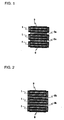
- FIG. 1 is a schematic cross-sectional view of an embodiment of an electrochemical cell stack according to this invention.
- a plurality of units 1 are stacked via conductors 8a and pressure plates 9 are disposed on both ends in the stacking direction.
- the conductor intervening between the units may be made of a conducting material such as a metal plate and a graphite sheet such as a grafoil.
- the outer circumference of the conductor 8a has a shape corresponding to the inner circumference of the gasket 6, typically has the identical shape, and the conductor is contacted only with an area in the current collector where the cathode and the anode are disposed.
- the electrodes can be, therefore, evenly and adequately pressed by a pressure from the pressure plate 9.
- the pressure plates 9 disposed on both ends of the stack also has an outer circumference shape corresponding to, typically identical to the inner circumference of the gasket 6.
- the conductor or the pressure plate has an area of the face contacting with the unit equal to or less than that of inside region of the inner circumference of the gasket of the unit in a stacked plane thereof.
- Their area of the face contacting with the unit is preferably 90 % or more to the area of inner circumference of the gasket, more preferably 95 % or more.
- the conductor or the pressure plate may be a circular plate having an outer diameter equal to or less than the inner diameter of the gasket.
- the outer diameter of the circular plate is substantially equal to the outer diameter of the electrode disposed inside of the gasket for pressing the whole electrode-disposing area.
- the annular gasket and the circular plate may be disposed such that their centers are aligned on the same axis.
- FIG. 2 is a schematic cross-sectional view of another embodiment of an electrochemical cell stack according to this invention.
- a conductor 8b has a projection in the center in the thickness direction which extends to the outer circumference of the gasket. Such a projection formed in the conductor can significantly facilitate alignment of the unit with the conductor to improve a working efficiency in assembling.
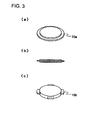
- FIG. 3 shows an embodiment of a conductor having a projection
- FiGs. 3(a) and 3(c) are perspective views
- FIG. 3(b) is a cross-sectional view.
- 10a denotes a projection formed in the whole outer circumference of the conductor
- 10b denotes a projection formed partially in the outer circumference of the conductor.
- the projection is used for alignment during assembling. It can be, therefore, formed in the whole outer circumference of the conductor as illustrated in FIG. 3(a) or partially in the outer circumference of the conductor as illustrated in FIG. 3(c).
- FIG. 4 shows stack of a unit 1 and a conductor 8b using a projection 10a in the conductor. Since the unit 1 and the projection 10a in the conductor 8a have outer shapes with a substantially equal outer diameter as shown in FIG. 4, an alignment member (not shown) contacting at least at three points in the outer circumference may be used to facilitate alignment.
- an electrochemical cell which is operable such that as a charge carrier, protons are exclusively involved in a redox reaction associated with charge/discharge in both electrodes. More specifically, preferred is an electrochemical cell comprising an electrolytic solution containing a proton source, where a proton concentration in the electrolyte and an operating voltage are controlled to allow the cell to operate such that bonding/elimination of a proton in the electrode active material may be exclusively involved in electron transfer in a redox reaction in both electrodes associated with charge/discharge.
- the following reaction equation shows a reaction of polyindole as one of proton-conducting compounds.
- the first step shows a doping reaction, where X - represents a dopant ion such as sulfonate and halide ions, which can dope a proton-conducting compound to endow the compound with electrochemical activity.
- the second step shows an electrochemical reaction (electrode reaction) involving bonding/elimination of a proton in a doped compound.
- bonding/elimination of a proton is exclusively involved in electron transfer in a redox reaction, so that only protons are transferred during charge/discharge.
- an electrode active material in this invention is a proton-conducting compound, which is an organic compound (including a polymer) capable of storing electrochemical energy by a reaction with ions of an electrolyte.
- Such a proton-conducting compound may be any of known compound conventionally used; for example, ⁇ -conjugated polymers such as polyaniline, polythiophene, polypyrrole, polyacetylene, poly-p-phenylene, polyphenylene-vinylene, polyperinaphthalene, polyfuran, polyflurane, polythienylene, polypyridinediyl, polyisothianaphthene, polyquinoxaline, polypyridine, polypyrimidine, polyindole, polyaminoanthraquinone, polyimidazole and their derivatives; indole ⁇ -conjugated compound such as an indole trimer compound; quinones such as benzoquinone, naphthoquinone and anthraquinone; quinone polymers such as polyanthraquinone, polynaphthoquinone and polybenzoquinone where a quinone oxygen can be converted into a
- a proton-conducting compound examples include ⁇ -conjugated compounds or polymers having a nitrogen atom, quinone compounds and quinone polymers.
- a proton source in the proton-source-containing (proton donating) electrolyte may be an inorganic or organic acid.
- an inorganic acid include sulfuric acid, nitric acid, hydrochloric acid, phosphoric acid, tetrafluoroboric acid, hexafluorophosphoric acid and hexafluorosilicic acid.
- an organic acid include saturated monocarboxylic acids, aliphatic carboxylic acids, oxycarboxylic acids, p-toluenesulfonic acid, polyvinylsulfonic acid and lauric acid.
- an aqueous acid-containing solution is preferable and an aqueous solution of sulfuric acid is more preferable.
- a proton concentration in an electrolytic solution containing a proton source is preferably 10 -3 mol/L or more, more preferably 10 -1 mol/L or more in the light of reactivity of the electrode materials while being preferably 18 mol/L or less, more preferably 7 mol/L or less in the light of prevention of deterioration in activity of the electrode materials and dissolution of the electrode materials.
- an electrochemical cell unit may have in principle a conventional structure, a unit configuration will be described with reference to FIG. 5.
- a polyindole consisting of the unit represented by the following formula as a cathodic electrode active material
- vapor-grown carbon as a conduction auxiliary in 20 wt% to the electrode active material
- a polyvinylidene fluoride with an average molecular weight of 1,100 in 8 wt% was stirred using a blender.
- the resulting mixture was hot-pressed to form a cathode 2 (outside diameter: 13.2 mm).
- anodic electrode active material a polyphenylquinoxaline represented by the following formula as an anodic electrode active material were added vapor-grown carbon as a conduction auxiliary in 25 wt% to the electrode active material and the mixture was stirred using a blender. The resulting mixture was hot-pressed to form an anode 3 (outside diameter: 13.2 mm).
- the cathode and the anode were impregnated with an electrolytic solution.
- the electrolytic solution was a 20 wt% aqueous solution of sulfuric acid.
- the cathode and the anode were laminated via porous polypropylene with a thickness of 150 ⁇ m as a separator.
- the resulting laminate was combined with a cathodic and an anodic current collectors 4,5 made of a conductive rubber and a gasket 6 made of a rubbery material, and the current collectors and the annular gasket (outside diameter: 16.2 mm, inside diameter: 14.2 mm) were glued by vulcanization to prepare an electrochemical cell unit 1.
- vulcanization gluing was used in this example, this invention is not limited to the specific method as long as stable adhesion can be achieved.
- An electrochemical cell stack was prepared as described in Example 1, except using a stainless plate with a thickness of 100 ⁇ m as a conductor.
- An electrochemical cell stack was prepared as described in Example 1, except using a conductor with a thickness of 200 ⁇ m having a projection in the center in the thickness direction.
- the cross-sectional shape of the electrochemical cell stack was as described in FIG. 2 except the number of the stacked units.
- An electrochemical cell stack was prepared as described in Example 1, except that the number of the stacked units 1 was three.
- An electrochemical cell stack was prepared as described in Example 1, except that no intervening conductors were used.
- the cross-sectional shape of the electrochemical cell stack was as described in FIG. 6 except the number of the stacked units.
- An electrochemical cell stack was prepared as described in Comparative Example 1, except that the number of the units was three.
- An electrochemical cell stack was prepared as described in Example 1, except that six units were stacked via alternate stainless plate conductor with a thickness of 200 ⁇ m.
- the cross-sectional shape of the electrochemical cell stack was as described in FIG. 7 except the number of the stacked units. That is, the electrochemical cell stack corresponds to the stack described in Patent Reference 1.
- ESR equivalent series resistance
- this invention has been described, taking a secondary battery as an example, but this invention would be similarly effective when being applied to another type of storage device such as an electric double layer capacitor.
Landscapes
- Engineering & Computer Science (AREA)
- Power Engineering (AREA)
- Chemical Kinetics & Catalysis (AREA)
- Chemical & Material Sciences (AREA)
- Electrochemistry (AREA)
- General Chemical & Material Sciences (AREA)
- Microelectronics & Electronic Packaging (AREA)
- Structural Engineering (AREA)
- Manufacturing & Machinery (AREA)
- Civil Engineering (AREA)
- Architecture (AREA)
- Electric Double-Layer Capacitors Or The Like (AREA)
- Secondary Cells (AREA)
- Hybrid Cells (AREA)
Applications Claiming Priority (4)
| Application Number | Priority Date | Filing Date | Title |
|---|---|---|---|
| JP2003135770 | 2003-05-14 | ||
| JP2003135770 | 2003-05-14 | ||
| JP2003208540 | 2003-08-25 | ||
| JP2003208540 | 2003-08-25 |
Publications (2)
| Publication Number | Publication Date |
|---|---|
| EP1478036A2 true EP1478036A2 (de) | 2004-11-17 |
| EP1478036A3 EP1478036A3 (de) | 2007-01-03 |
Family
ID=33032388
Family Applications (1)
| Application Number | Title | Priority Date | Filing Date |
|---|---|---|---|
| EP04252738A Withdrawn EP1478036A3 (de) | 2003-05-14 | 2004-05-12 | Elektrochemischer Zellenstapel |
Country Status (5)
| Country | Link |
|---|---|
| US (1) | US20040229117A1 (de) |
| EP (1) | EP1478036A3 (de) |
| KR (1) | KR20040098546A (de) |
| CN (1) | CN100383904C (de) |
| TW (1) | TWI234308B (de) |
Families Citing this family (31)
| Publication number | Priority date | Publication date | Assignee | Title |
|---|---|---|---|---|
| JP2007273350A (ja) * | 2006-03-31 | 2007-10-18 | Toyota Motor Corp | 積層型電池およびその製造方法 |
| GB0607957D0 (en) * | 2006-04-21 | 2006-05-31 | Imp Innovations Ltd | Energy storage device |
| JP4569534B2 (ja) * | 2006-07-19 | 2010-10-27 | トヨタ自動車株式会社 | 組電池 |
| KR100955233B1 (ko) * | 2008-05-19 | 2010-04-29 | 비나텍주식회사 | 적층형 전기이중층 커패시터 |
| CN102210023B (zh) * | 2008-11-07 | 2015-09-30 | Sakti3有限公司 | 一体式结构中的多个电化学和聚能组件的制造方法和结构 |
| US20100316896A1 (en) * | 2009-06-10 | 2010-12-16 | Research In Motion Limited | Battery for wireless mobile communication device |
| US8760851B2 (en) | 2010-12-21 | 2014-06-24 | Fastcap Systems Corporation | Electrochemical double-layer capacitor for high temperature applications |
| US9214709B2 (en) | 2010-12-21 | 2015-12-15 | CastCAP Systems Corporation | Battery-capacitor hybrid energy storage system for high temperature applications |
| US12215572B2 (en) | 2010-12-21 | 2025-02-04 | Fastcap Ultracapacitors Llc | Power system for high temperature applications with rechargeable energy storage |
| US9001495B2 (en) | 2011-02-23 | 2015-04-07 | Fastcap Systems Corporation | High power and high energy electrodes using carbon nanotubes |
| CN104271880A (zh) | 2011-05-24 | 2015-01-07 | 快帽系统公司 | 用于高温应用的具有可再充电能量存储器的电力系统 |
| EP3796350A1 (de) | 2011-06-07 | 2021-03-24 | FastCAP SYSTEMS Corporation | Energieträgermedien für ultrakondensatoren |
| US9558894B2 (en) | 2011-07-08 | 2017-01-31 | Fastcap Systems Corporation | Advanced electrolyte systems and their use in energy storage devices |
| WO2013009720A2 (en) | 2011-07-08 | 2013-01-17 | Fastcap Systems Corporation | High temperature energy storage device |
| CN108868747A (zh) | 2011-11-03 | 2018-11-23 | 快帽系统公司 | 生产测井仪 |
| US10872737B2 (en) | 2013-10-09 | 2020-12-22 | Fastcap Systems Corporation | Advanced electrolytes for high temperature energy storage device |
| EP3084481B8 (de) | 2013-12-20 | 2024-01-03 | Fastcap Systems Corporation | Vorrichtung zur elektromagnetischen telemetrie |
| US11270850B2 (en) | 2013-12-20 | 2022-03-08 | Fastcap Systems Corporation | Ultracapacitors with high frequency response |
| CN113539696B (zh) | 2014-10-09 | 2024-12-03 | 快帽系统公司 | 用于储能装置的纳米结构化电极 |
| KR102668693B1 (ko) | 2015-01-27 | 2024-05-27 | 패스트캡 시스템즈 코포레이션 | 넓은 온도 범위 울트라커패시터 |
| KR102645762B1 (ko) | 2015-10-27 | 2024-03-11 | 메사추세츠 인스티튜트 오브 테크놀로지 | 전기화학적 기체 분리 방법 |
| KR102635455B1 (ko) | 2016-05-20 | 2024-02-13 | 교세라 에이브이엑스 컴포넌츠 코포레이션 | 고온용 울트라커패시터 |
| MY195773A (en) | 2016-05-20 | 2023-02-11 | Kyocera Avx Components Corp | Multi-Cell Ultracapacitor |
| FR3054372A1 (fr) * | 2016-07-21 | 2018-01-26 | St Microelectronics Tours Sas | Montage de composants electroniques |
| US11830672B2 (en) | 2016-11-23 | 2023-11-28 | KYOCERA AVX Components Corporation | Ultracapacitor for use in a solder reflow process |
| EP3549148B1 (de) | 2016-12-02 | 2025-01-01 | Fastcap Systems Corporation | Verbundelektrode |
| US11557765B2 (en) | 2019-07-05 | 2023-01-17 | Fastcap Systems Corporation | Electrodes for energy storage devices |
| KR20220053626A (ko) | 2019-08-28 | 2022-04-29 | 메사추세츠 인스티튜트 오브 테크놀로지 | 루이스 산 기체의 전기화학적 포집 |
| US11598012B2 (en) | 2019-08-28 | 2023-03-07 | Massachusetts Institute Of Technology | Electrochemically mediated gas capture, including from low concentration streams |
| US11404210B2 (en) * | 2019-10-10 | 2022-08-02 | Applied Optoelectronics, Inc. | Capacitor stacks for noise filtering in high-frequency switching applications and an optical subassembly module implementing same |
| EP4731817A2 (de) | 2023-06-26 | 2026-04-29 | Universidade Do Porto | Elektrochemische vorrichtung und entsprechende verwendungen |
Family Cites Families (9)
| Publication number | Priority date | Publication date | Assignee | Title |
|---|---|---|---|---|
| US2487985A (en) * | 1945-11-21 | 1949-11-15 | Ruben Samuel | Thermoplastic conductive joint for flat cells |
| US3615867A (en) * | 1969-07-11 | 1971-10-26 | Esb Inc | Method of assembling a battery with intercell connectors |
| JPH01232657A (ja) * | 1988-03-11 | 1989-09-18 | Fuji Elelctrochem Co Ltd | 積層電池 |
| JPH04237109A (ja) * | 1991-01-22 | 1992-08-25 | Nec Corp | 電気二重層コンデンサとその製造方法 |
| JPH06215794A (ja) * | 1993-01-18 | 1994-08-05 | Shin Kobe Electric Mach Co Ltd | 薄形密閉形蓄電池 |
| US5374490A (en) * | 1993-05-19 | 1994-12-20 | Portable Energy Products, Inc. | Rechargeable battery |
| US6068947A (en) * | 1997-10-20 | 2000-05-30 | Micron Technology, Inc. | Thin-profile battery circuits and constructions and button-type battery circuits and constructions |
| JPH11340093A (ja) * | 1998-05-22 | 1999-12-10 | Nec Corp | 電気二重層コンデンサ |
| JP2002075788A (ja) * | 2000-09-05 | 2002-03-15 | Nec Corp | 電気二重層コンデンサおよび電池セルの積層体 |
-
2004
- 2004-05-04 US US10/838,742 patent/US20040229117A1/en not_active Abandoned
- 2004-05-12 EP EP04252738A patent/EP1478036A3/de not_active Withdrawn
- 2004-05-12 CN CNB2004100387006A patent/CN100383904C/zh not_active Expired - Fee Related
- 2004-05-12 KR KR1020040033266A patent/KR20040098546A/ko not_active Ceased
- 2004-05-13 TW TW093113472A patent/TWI234308B/zh not_active IP Right Cessation
Also Published As
| Publication number | Publication date |
|---|---|
| CN1551262A (zh) | 2004-12-01 |
| US20040229117A1 (en) | 2004-11-18 |
| TWI234308B (en) | 2005-06-11 |
| KR20040098546A (ko) | 2004-11-20 |
| TW200425565A (en) | 2004-11-16 |
| EP1478036A3 (de) | 2007-01-03 |
| CN100383904C (zh) | 2008-04-23 |
Similar Documents
| Publication | Publication Date | Title |
|---|---|---|
| EP1478036A2 (de) | Elektrochemischer Zellenstapel | |
| US8574736B2 (en) | Hybrid-typed electrode assembly of capacitor-battery structure | |
| US6869731B2 (en) | Electrolytic solution and electrochemical cell using the same | |
| US7035084B2 (en) | Secondary battery and capacitor using indole polymeric compound | |
| EP2043188B1 (de) | Elektrische speicheranordnung | |
| US6222723B1 (en) | Asymmetric electrochemical capacitor and method of making | |
| EP1630834A1 (de) | Elektrischer doppelschichtkondensator und elektrolytische zelle | |
| US6301093B1 (en) | Electrochemical capacitor | |
| US20020089807A1 (en) | Polymer electrochemical capacitors | |
| KR100586823B1 (ko) | 전기화학 셀 용 전극 및 그것을 이용한 전기화학 셀 | |
| JP2005100926A (ja) | 電気化学セル積層体 | |
| JP2008288028A (ja) | 電気化学セル用電極および電気化学セル | |
| US6099989A (en) | Polymer secondary batteries | |
| US20040214078A1 (en) | Electrochemical cell | |
| CN217035901U (zh) | 一种内部串联型固态电池及固态电池组 | |
| JP5105401B2 (ja) | 電極活物質及びそれを用いた電気化学素子 | |
| JP2004342595A (ja) | 電気化学セル用電極およびそれを用いた電気化学セル | |
| KR100955233B1 (ko) | 적층형 전기이중층 커패시터 | |
| JP4073025B2 (ja) | 電気化学セル | |
| KR20240134649A (ko) | 정체형 아연-요오드 레독스 전지 | |
| JP2023098109A (ja) | レドックスキャパシタおよびレドックスキャパシタシステム | |
| JP2000195500A (ja) | 積層型蓄電素子及びその製造方法 | |
| JPH02177266A (ja) | 鉛蓄電池 |
Legal Events
| Date | Code | Title | Description |
|---|---|---|---|
| PUAI | Public reference made under article 153(3) epc to a published international application that has entered the european phase |
Free format text: ORIGINAL CODE: 0009012 |
|
| AK | Designated contracting states |
Kind code of ref document: A2 Designated state(s): AT BE BG CH CY CZ DE DK EE ES FI FR GB GR HU IE IT LI LU MC NL PL PT RO SE SI SK TR |
|
| AX | Request for extension of the european patent |
Extension state: AL HR LT LV MK |
|
| PUAL | Search report despatched |
Free format text: ORIGINAL CODE: 0009013 |
|
| AK | Designated contracting states |
Kind code of ref document: A3 Designated state(s): AT BE BG CH CY CZ DE DK EE ES FI FR GB GR HU IE IT LI LU MC NL PL PT RO SE SI SK TR |
|
| AX | Request for extension of the european patent |
Extension state: AL HR LT LV MK |
|
| 17P | Request for examination filed |
Effective date: 20070124 |
|
| AKX | Designation fees paid |
Designated state(s): DE FR GB |
|
| 17Q | First examination report despatched |
Effective date: 20071016 |
|
| STAA | Information on the status of an ep patent application or granted ep patent |
Free format text: STATUS: THE APPLICATION IS DEEMED TO BE WITHDRAWN |
|
| 18D | Application deemed to be withdrawn |
Effective date: 20101201 |