EP1477363A2 - Rückstelleinrichtung für einen Blinkerschalthebel - Google Patents
Rückstelleinrichtung für einen Blinkerschalthebel Download PDFInfo
- Publication number
- EP1477363A2 EP1477363A2 EP04010326A EP04010326A EP1477363A2 EP 1477363 A2 EP1477363 A2 EP 1477363A2 EP 04010326 A EP04010326 A EP 04010326A EP 04010326 A EP04010326 A EP 04010326A EP 1477363 A2 EP1477363 A2 EP 1477363A2
- Authority
- EP
- European Patent Office
- Prior art keywords
- sliding element
- spring
- reset device
- axis
- trigger
- Prior art date
- Legal status (The legal status is an assumption and is not a legal conclusion. Google has not performed a legal analysis and makes no representation as to the accuracy of the status listed.)
- Granted
Links
- 230000014759 maintenance of location Effects 0.000 claims description 21
- 230000004888 barrier function Effects 0.000 claims description 17
- 229910000639 Spring steel Inorganic materials 0.000 claims description 7
- 238000006073 displacement reaction Methods 0.000 claims description 2
- 230000007246 mechanism Effects 0.000 abstract description 2
- 229910000831 Steel Inorganic materials 0.000 abstract 1
- 239000010959 steel Substances 0.000 abstract 1
- 230000008878 coupling Effects 0.000 description 4
- 238000010168 coupling process Methods 0.000 description 4
- 238000005859 coupling reaction Methods 0.000 description 4
- 230000008901 benefit Effects 0.000 description 3
- 230000036316 preload Effects 0.000 description 2
- 230000009467 reduction Effects 0.000 description 2
- 230000001960 triggered effect Effects 0.000 description 2
- 241000196324 Embryophyta Species 0.000 description 1
- 240000002834 Paulownia tomentosa Species 0.000 description 1
- 235000010678 Paulownia tomentosa Nutrition 0.000 description 1
- 238000000034 method Methods 0.000 description 1
- 230000000452 restraining effect Effects 0.000 description 1
- 230000000717 retained effect Effects 0.000 description 1
Images


Classifications
-
- B—PERFORMING OPERATIONS; TRANSPORTING
- B60—VEHICLES IN GENERAL
- B60Q—ARRANGEMENT OF SIGNALLING OR LIGHTING DEVICES, THE MOUNTING OR SUPPORTING THEREOF OR CIRCUITS THEREFOR, FOR VEHICLES IN GENERAL
- B60Q1/00—Arrangement of optical signalling or lighting devices, the mounting or supporting thereof or circuits therefor
- B60Q1/26—Arrangement of optical signalling or lighting devices, the mounting or supporting thereof or circuits therefor the devices being primarily intended to indicate the vehicle, or parts thereof, or to give signals, to other traffic
- B60Q1/34—Arrangement of optical signalling or lighting devices, the mounting or supporting thereof or circuits therefor the devices being primarily intended to indicate the vehicle, or parts thereof, or to give signals, to other traffic for indicating change of drive direction
- B60Q1/40—Arrangement of optical signalling or lighting devices, the mounting or supporting thereof or circuits therefor the devices being primarily intended to indicate the vehicle, or parts thereof, or to give signals, to other traffic for indicating change of drive direction having mechanical, electric or electronic automatic return to inoperative position
- B60Q1/42—Arrangement of optical signalling or lighting devices, the mounting or supporting thereof or circuits therefor the devices being primarily intended to indicate the vehicle, or parts thereof, or to give signals, to other traffic for indicating change of drive direction having mechanical, electric or electronic automatic return to inoperative position having mechanical automatic return to inoperative position due to steering-wheel position, e.g. with roller wheel control
- B60Q1/425—Arrangement of optical signalling or lighting devices, the mounting or supporting thereof or circuits therefor the devices being primarily intended to indicate the vehicle, or parts thereof, or to give signals, to other traffic for indicating change of drive direction having mechanical, electric or electronic automatic return to inoperative position having mechanical automatic return to inoperative position due to steering-wheel position, e.g. with roller wheel control using a latching element for resetting a switching element
Definitions
- the invention relates to a reset device for Reset a turn signal lever Steering column switch device from a switch position in a starting position, with a shift lever side, around a pivot axis pivotable, holding sections having drivers, with at least one with the Holding sections interacting, housing-side System contour, the system contour retention areas for has the holding sections, with restoring means for Reset the shift lever the respective holding section trigger from the respective retention area, and with a trigger finger which can be deflected by a trigger axis and which is controlled by a cam on the steering wheel side can be actuated and the Reset means actuated.
- a reset device is known from DE 100 37 586 A1 became known in which the movement of the trigger finger is transmitted to barriers.
- the barrier doors are over a quite complex mechanism, the different rocker arms has motion-coupled with the trigger finger.
- Deflecting the trigger finger leads to swinging open the barrier doors, thereby releasing the holding sections and the steering lever is reset.
- the present invention is therefore based on the object based on a reset device at the beginning described type to the extent that they become one is very compact and the other is permanent works reliably.
- a from the a middle position can be moved in two release positions arranged sliding element, which in one Release position one and in the other release position the other holding section from the respective retention area triggers.
- a sliding element that is in two Trigger positions can be shifted, especially in Compared to DE 100 37 586 A1 a component reduction can be achieved. With only one component, namely the Sliding element, depending on the direction of movement of the Triggering finger triggered the respective holding section.
- the displacement of the Sliding element in the two release positions at least largely perpendicular to one intersecting the pivot axis Radius line of the steering spindle axis.
- Such one Arrangement has the advantage that the movement of the Trigger finger is transferred to the sliding element so that it travels as far as possible. This can a targeted and reliable triggering of the Holding sections can be reached.
- the Trigger finger For coupling the movement of the trigger finger and the Sliding element can be provided that the Trigger finger a running along its longitudinal axis, has a centrally arranged longitudinal guide into which a pin on the sliding element protrudes. About the tenon the sliding element depending on the actuation of the release finger from its middle position to the respective release position postponed. Can be used for exact guidance of the sliding element the sliding element in a groove, backdrop or the like be led.
- the Release finder by a spring element in Steering spindle axis spring-loaded so radial direction is arranged that the trigger finger opposite the pin is slidable along its longitudinal guide.
- the Trigger finger for example, in the area of its trigger axis in one on a radius line of the steering spindle axis lying groove can be arranged displaceably.
- the spring element is advantageously simple curved spring steel band or as a simple curved Spring steel wire trained.
- a spring element can for example be bent by approximately 180 ° and the Trigger finger perpendicular to its trigger axis in the radial Apply direction towards the steering spindle axis.
- Such spring element can consequently in the radial direction build the steering spindle axis very compact. This allows the entire reset device in the radial direction be kept comparatively small.
- the groove runs here advantageously on the radius line of the Steering shaft axis.
- the groove advantageously takes one Trigger axis having pin portion of the Trigger finger on.
- the parallel to the steering spindle axis extending pin section advantageously engages into the groove.
- the sliding element with a Compensating spring is coupled.
- the balance spring is advantageously in the form of a coil spring trained under axial preload in a housing-side spring holder is held, the Sliding element two the end faces of the coil spring has overlapping and / or encompassing spring contact sections.
- the compensating spring is advantageously transverse to Steering spindle axis arranged.
- a preferred embodiment of the invention provides that the sliding element along a straight line is slidably arranged, the straight line perpendicular to the connecting line of the steering spindle axis with the Swivel axis runs.
- the Sliding element slidable along a circular path can be arranged, the center of the circular path in the area of the steering spindle axis or on a radius line the steering spindle axis in the area between the Steering spindle axis and the sliding element.
- the center of the circular path can be a corresponding one Deflection of the sliding element can be achieved, creating a Triggering can be effected.
- the sliding element advantageously acts to trigger the respective holding section directly against the respective Holding portion. This has the advantage that compared to known reset devices a component reduction is achieved.
- the retention areas of the System contour in the form of retention bulges are and if the sliding element the respective Holding section in the release position from the respective Retention bulge.
- a particularly positive one Switching behavior arises when the sections of the Sliding element, which the respective holding section from the Lift out the respective retention bulge in the Limit the trigger position tangentially to the system contour and / or merge tangentially into the system contour.
- Another embodiment of the invention provides that the sliding element to trigger the respective Holding section directly against the respective Holding section in the respective retention area Barrier door works and deflects it.
- This shows Embodiment additional components in the form of barrier doors on.
- the barrier doors have the advantage, however, that they can be moved so that a small but precise Deflection is sufficient to trigger the holding sections.
- the Sliding element with the respective barrier door over a sliding element side slide and one Barrier-side, running in the backdrop Guide pins are motion-coupled. This can in particular a linear movement of the sliding element be deflected into a pivoting movement of the barrier doors.
- the longitudinal axis of the slide track can be such that the guide pin of the respective Barrier door in the release position the respective barrier door deflects. This can be a very accurate and precise Switching behavior and resetting can be realized.
- Sections of the slide tracks in which the guide pin are arranged in the central position of the sliding element perpendicular to one intersecting the swivel axis Radius line of the steering spindle axis.
- the holding sections along each Radius line of the swivel axis against the respective Plant contour act spring-loaded, these two Radius lines form an angle in the range from 90 ° to 135 ° lock in. By providing such an angle builds the reset device according to the invention comparatively small.
- FIGs 1 to 5 is an inventive Reset device 10 for resetting a shift lever 12 a steering column switching device is shown.
- the shift lever 12 respectively with the shift lever 12 firmly connected driver 14 in the Starting position shown.
- the driver 14 and the Shift levers 12 are about a pivot axis 16 of the Starting position pivotable into a switch position.
- the driver 14 has two Holding sections 18, 20, each along one Radius line of the pivot axis 16 against one housing contour 22, 24 act.
- the Contact contours 22, 24 have retention areas 26, 28, in which the holding sections 18 in the respective Switch position are retained.
- the reset device 10 also sees one by one Release axis 30 deflectable trigger finger 32 in front of a steering wheel side cam 34 in the switch position can be actuated.
- the cam 34 is, for example, medium or directly on the steering wheel or on a steering shaft a steering spindle axis 36 is rotatably arranged.
- the trigger finger 32 is with a sliding element 44 coupled, which is displaceable along a straight line 46 is arranged.
- the straight line 46 runs perpendicular to Connecting line of the steering spindle axis 36 with the Pivot axis 16.
- the sliding element 44 is of one in the Figure 1 shown middle position in two release positions displaceable, the one release position in FIG is shown.
- the sliding element Pin 48 running parallel to the steering spindle axis 36 on. The pin projects into a along the longitudinal axis of the Release finger 32 longitudinal guide 50.
- the sliding element 44 For coupling the movement of the sliding element 44 with the two Barrier doors 40, the sliding element has two backdrop tracks 52, into the guide pin 54 on the lock door side intervene in a motion-coupled manner. Because of the kinked trained slide tracks 52 is achieved in that Deflecting the trigger finger 32 the respective barrier door 40 is deflected. The barrier door 40 is deflected in such a way that the area 42 of the barrier door 40 the corresponding Holding section 18, 20 releases. In Figure 5.1, the one 3.1 shows the corresponding section shown that by pivoting the barrier door 40 to the axis 38 the area 42 releases the holding section 18, so that a reset of the shift lever 12 is effected.
- the trigger finger 32 is in the initial position according to Figure 1 arranged in a restraining position such that he cannot come into contact with the cam 34. Only at; only when When the shift lever 12 is actuated, the trigger finger 32 arrives to an advanced position in which it is removed from the cam 32 can be deflected.
- the trigger finger 32 of a spring element in the form of a simply curved Spring steel wire 58 towards the steering spindle axis 36 arranged spring loaded.
- spring steel wire 16 is in a receiving groove 60 arranged, such as clearly in Figure 1 or 3 can be seen.
- the other end 62 of the spring steel wire 58 acts on the Release finger 32 in the direction of the steering spindle axis 36 Direction.
- the trigger finger 32 via its pin portion 64 in a groove 76 on the housing side.
- the groove 76 can the trigger finger about its pivot axis 30 through the cam 34 can be pivoted.
- the sliding element 44 with a compensating spring in the form a coil spring 70 is coupled such that after the Resetting the shift lever 12, the sliding element 44 in the Starting position is returned.
- the coil spring 70 is advantageously under axial preload in a spring mount on the housing side held. Such a spring holder is shown in FIG 72 clearly recognizable.
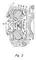
- the holding sections 18, 20 each act along one Radius line of the pivot axis 16 against the respective Contact contour 22, which is particularly clear from Figure 2 becomes.
- the two radius lines close an angle ⁇ of about 125 °.
- the holding sections 18 are 20 against the contact contours 22 by means of coil springs 74 spring-loaded.
- the second shown in Figures 6 to 10 Embodiment of the invention shows a Reset device 80, in the case of the reset device 10 corresponding components corresponding reference numbers wear.
- the Reset device 80 has a sliding element 84, the along a circular path, which is identified by the reference symbol 86 is marked to be displaceable about the steering spindle axis 36 is stored.
- the sliding element 84 has a pin 48 which in the Longitudinal guide 50 engages the release finger 32.
- Figure 7 shows a section parallel to Viewing plane through Figure 6, in which the Contact contours 22, 24 and the holding sections 18, 20 of the Driver 14 are clearly visible.
- the system contours 22, 24 have retention areas 26, 28 in the form of Bulges on.
- the two are Holding sections 18, 20 in one Output Stel Lungau book Tung.
- the coil spring 70 is also clearly closed recognize the biased in the spring receptacle 72 is arranged.
- the area of the end faces of the Spring receptacles 72 are radial around the steering spindle axis 36 extending guide groove portions 88 are provided.
- guide groove portions 88 are provided in the two guide groove portions 88 each protrudes in the Figure 7 not shown guide pin 90 of the Sliding element 84. Due to the in the guide sections 88 protruding guide pin 90 becomes the sliding element along the circular path 86 around the steering spindle axis 36 slidably guided.
- the guide pins are also like this arranged such that when the sliding element 84 is deflected act on the free end faces of the coil spring 70. This ensures that the sliding element after Reset of the shift lever 12 in its central, in the Figure 6 shown, starting position is moved back.
- FIG. 8 shows the switching position of the shift lever 12. Because of the backdrop clearly visible in FIG. 7 66 protrudes in the switch position according to FIG Trigger finger 32 in the radial direction towards the pivot axis 36, so that the cam 34 when turning the steering wheel back Trigger finger 32 operated. In Figure 8 is clearly too recognize that the holding portion 18 in the Retention area 26 is arranged. It can also be seen that the free ends 92, 94 of the sliding element 84 in Area of the retention areas 26, 28 are.
- the Reset device 10 are the holding sections 18, 20 of the Reset device 80 housed in guide sleeves 96 and by means, not shown, in the guide sleeves 96 existing coil springs against the respective Contact contour 22, 24 spring-loaded.
Landscapes
- Engineering & Computer Science (AREA)
- Mechanical Engineering (AREA)
- Lock And Its Accessories (AREA)
- Lighting Device Outwards From Vehicle And Optical Signal (AREA)
Abstract
Description
Claims (17)
- Rückstelleinrichtung (10, 80) zur Rückstellung eines Blinkerschalthebels (12) einer Lenkstockschaltervorrichtung von einer Schaltstellung in eine Ausgangstellung, mit einem schalthebelseitigen, um eine Schwenkachse (16) verschwenkbaren, Halteabschnitte (18, 20) aufweisenden Mitnehmer (14), mit wenigstens einer mit den Halteabschnitten (18, 20) zusammenwirkenden, gehäuseseitigen Anlagekontur (22, 24), wobei die Anlagekontur (22, 24) Rückhaltebereiche (26, 28) für die Halteabschnitte ((18, 20)aufweist, mit Rückstellmitteln, die zur Rückstellung des Schalthebels (12) den jeweiligen Halteabschnitt (18, 20) aus dem jeweiligen Rückhaltebereich (26, 28) auslösen, und mit einem um eine Auslöseachse (30) auslenkbaren Auslösefinger (32), der von einem lenkradseitigen Nocken (34) betätigbar ist und die Rückstellmittel betätigt, dadurch gekennzeichnet, dass die Rückstellmittel ein mit dem Auslösefinger (32) gekoppeltes, von einer Mittellage aus in zwei Auslöselagen verschiebbar angeordnetes Schiebeelement (44, 84) umfassen, das in der einen Auslöselage den einen und in der anderen Auslöselage den anderen Halteabschnitt (18, 20) aus dem jeweiligen Rückhaltebereich (26, 28) auslöst.
- Rückstelleinrichtung (10, 80) nach Anspruch 1, dadurch gekennzeichnet, dass die Verschiebung des Schiebeelements (44, 84) in die zwei Auslöselagen wenigstens weitgehend senkrecht zu einer die Schwenkachse (16) schneidenden Radiuslinie der Lenkspindelachse (36) erfolgt.
- Rückstelleinrichtung (10, 80) nach Anspruch 1 oder 2, dadurch gekennzeichnet, dass der Auslösefinger (32) eine entlang seiner Längsachse verlaufende, mittig angeordnete Längsführung (50) aufweist, in die ein schiebeelementseitiger Zapfen (48) ragt.
- Rückstelleinrichtung(10, 80) nach einem der vorhergehenden Ansprüche, dadurch gekennzeichnet, dass der Auslösefinger (32) durch ein Federelement (58) in zur Lenkspindelachse (36) radialer Richtung federbeaufschlagt so angeordnet ist, dass der Auslösefinger (32) gegenüber dem Zapfen entlang seiner Längsachse verschiebbar ist.
- Rückstelleinrichtung (10, 80) nach Anspruch 4, dadurch gekennzeichnet, dass das Federelement (58) als einfach gebogenes Federstahlband oder als einfach gebogener Federstahldraht ausgebildet ist.
- Rückstelleinrichtung (10, 80) nach Anspruch 4 oder 5, dadurch gekennzeichnet, dass das dem Federelement (58) zugewandte Ende (64) des Auslösefingers in einer gehäuseseitigen Nut (76) geführt wird.
- Rückstelleinrichtung (10, 80) nach einem der vorhergehenden Ansprüche, dadurch gekennzeichnet, dass das Schiebeelement (44, 84) mit einer Ausgleichsfeder (70) gekoppelt ist, die nach dem Rückstellen des Schalthebels (12) das Schiebeelement (44, 84) in die Ausgangslage rückführt.
- Rückstelleinrichtung (10, 80) nach Anspruch 7, dadurch gekennzeichnet, dass die Ausgleichsfeder in Form einer Schraubenfeder (70) ausgebildet ist, die unter axialer Vorspannung in einer gehäuseseitigen Federaufnahme (72) gehalten wird, wobei das Schiebeelement (44, 84) zwei die Stirnseiten der Schraubenfeder (72) über- und/oder umgreifende Federanlageabschnitte (90) aufweist.
- Rückstelleinrichtung (10) nach einem der vorhergehenden Ansprüche, dadurch gekennzeichnet, dass das Schiebeelement (44) entlang einer geraden Linie (46) verschiebbar angeordnet ist, wobei die gerade Linie (46) senkrecht zur Verbindungslinie der Lenkspindelachse (36) mit der Schwenkachse (16) verläuft.
- Rückstelleinrichtung (80) nach einem der Ansprüche 1 bis 8, Ansprüche, dadurch gekennzeichnet, dass das Schiebeelement (84) entlang einer Kreisbahn (86) verschiebbar angeordnet ist, wobei der Mittelpunkt der Kreisbahn (84) im Bereich der Lenkspindelachse oder auf einer Radiuslinie der Lenkspindelachse (36) im Bereich zwischen der Lenkspindelachse (36) und dem Schiebelement (84) liegt.
- Rückstelleinrichtung (84) nach einem der vorhergehenden Ansprüche, dadurch gekennzeichnet, dass das Schiebeelement (84) zum Auslösen des jeweiligen Halteabschnitts unmittelbar gegen den jeweiligen Haltabschnitt wirkt.
- Rückstelleinrichtung (80) nach Anspruch 11, dadurch gekennzeichnet, dass die Rückhaltebereiche (26, 28) der Anlagekontur (22, 24) in Form von Rückhalteausbuchtungen ausgebildet sind und dass das Schiebeelement (84) den jeweiligen Halteabschnitt (18, 20) aus der jeweiligen Rückhalteausbuchtung heraushebt.
- Rückstelleinrichtung (80) nach Anspruch 12, dadurch gekennzeichnet, dass die Abschnitte (92, 94) des Schiebeelements (84), die den jeweiligen Halteabschnitt (18, 20) aus der jeweiligen Rückhalteausbuchtung (26, 28) herausheben, in der Auslöselage wenigstens weitgehend tangential an die Anlagekontur (22, 24) angrenzen und/oder tangential in die Anlagekontur (22, 24) übergehen.
- Rückstelleinrichtung(10) nach einem der Ansprüche 1 bis 10, dadurch gekennzeichnet, dass das Schiebeelement (44) zum Auslösen des jeweiligen Halteabschnitts (18, 20) unmittelbar gegen eine den jeweiligen Halteabschnitt (18, 20) im jeweiligen Rückhaltebereich (22, 24) haltende Sperrtüre (40) wirkt und diese auslenkt.
- Rückstelleinrichtung (10) nach Anspruch 14, dadurch gekennzeichnet, dass das Schiebeelement (44) mit den Sperrtüren (40) über schiebeelementseitige Kulissenbahnen (52) und sperrtürenseitige, in den Kulissenbahnen (52) laufenden Führungszapfen (54) bewegungsgekoppelt sind.
- Rückstelleinrichtung (10) nach Anspruch 15, dadurch gekennzeichnet, dass die Längsachse der jeweiligen Kulissenbahn (52) derart geknickt verläuft, dass der Führungszapfen (54) der jeweiligen Sperrtüre (40) in der Auslöselage die jeweilige Sperrtüre (40) auslenkt.
- Rückstelleinrichtung (10, 80) nach einem der vorhergehenden Ansprüche, dadurch gekennzeichnet, dass die Halteabschnitte (18, 20) entlang je einer Radiuslinie der Schwenkachse (16) gegen die jeweilige Anlagekontur (22, 24) federbeaufschlagt wirken, wobei diese beiden Radiuslinien einen Winkel (α) von cirka 90° bis 135° einschließen.
Applications Claiming Priority (2)
| Application Number | Priority Date | Filing Date | Title |
|---|---|---|---|
| DE2003121408 DE10321408A1 (de) | 2003-05-13 | 2003-05-13 | Rückstelleinrichtung für einen Blinkerschalthebel |
| DE10321408 | 2003-05-13 |
Publications (3)
| Publication Number | Publication Date |
|---|---|
| EP1477363A2 true EP1477363A2 (de) | 2004-11-17 |
| EP1477363A3 EP1477363A3 (de) | 2006-04-26 |
| EP1477363B1 EP1477363B1 (de) | 2007-11-07 |
Family
ID=33016364
Family Applications (1)
| Application Number | Title | Priority Date | Filing Date |
|---|---|---|---|
| EP20040010326 Expired - Lifetime EP1477363B1 (de) | 2003-05-13 | 2004-04-30 | Rückstelleinrichtung für einen Blinkerschalthebel |
Country Status (3)
| Country | Link |
|---|---|
| EP (1) | EP1477363B1 (de) |
| DE (2) | DE10321408A1 (de) |
| ES (1) | ES2295725T3 (de) |
Cited By (2)
| Publication number | Priority date | Publication date | Assignee | Title |
|---|---|---|---|---|
| EP1691387A1 (de) * | 2005-02-09 | 2006-08-16 | Alps Electric Co., Ltd. | Schaltervorrichtung für Fahrrichtungsanzeige |
| CN102935824A (zh) * | 2012-10-25 | 2013-02-20 | 昌辉汽车电器(黄山)股份公司 | 一种汽车转向回位结构 |
Citations (3)
| Publication number | Priority date | Publication date | Assignee | Title |
|---|---|---|---|---|
| US3300601A (en) * | 1965-02-15 | 1967-01-24 | Essex Wire Corp | Turn signal |
| DE10037585A1 (de) * | 2000-08-02 | 2002-02-14 | Valeo Schalter & Sensoren Gmbh | Rückstellvorrichtung für einen Blinkerschalter in Kraftfahrzeugen |
| DE10037586A1 (de) * | 2000-08-02 | 2002-02-21 | Valeo Schalter & Sensoren Gmbh | Rückstellvorrichtung für einen Blinkerschalter in Kraftfahrzeugen |
Family Cites Families (6)
| Publication number | Priority date | Publication date | Assignee | Title |
|---|---|---|---|---|
| DE856416C (de) * | 1950-01-13 | 1952-11-20 | Bosch Gmbh Robert | Elektrischer Schalter fuer Fahrtrichtungsanzeiger von Kraftfahrzeugen |
| DE2022436C3 (de) * | 1970-05-08 | 1973-12-13 | Swf-Spezialfabrik Fuer Autozubehoer Gustav Rau Gmbh, 7120 Bietigheim | Lenkstockschalter mit selbst tatiger Ruckstellung zur Fahrtnchtungs anzeige fur Kraftfahrzeuge |
| JPH048033Y2 (de) * | 1987-08-12 | 1992-03-02 | ||
| JPH0621789Y2 (ja) * | 1989-02-22 | 1994-06-08 | 株式会社東海理化電機製作所 | ターンシグナルスイッチのセルフキャンセル装置 |
| JP2585025Y2 (ja) * | 1993-09-28 | 1998-11-11 | 株式会社東海理化電機製作所 | ターンシグナルのキャンセル装置 |
| DE19758288B4 (de) * | 1997-12-31 | 2006-10-26 | Valeo Schalter Und Sensoren Gmbh | Verfahren und Vorrichtung zur drehrichtungsgekoppelten Rückstellung eines Schalters |
-
2003
- 2003-05-13 DE DE2003121408 patent/DE10321408A1/de not_active Withdrawn
-
2004
- 2004-04-30 ES ES04010326T patent/ES2295725T3/es not_active Expired - Lifetime
- 2004-04-30 DE DE200450005412 patent/DE502004005412D1/de not_active Expired - Lifetime
- 2004-04-30 EP EP20040010326 patent/EP1477363B1/de not_active Expired - Lifetime
Patent Citations (3)
| Publication number | Priority date | Publication date | Assignee | Title |
|---|---|---|---|---|
| US3300601A (en) * | 1965-02-15 | 1967-01-24 | Essex Wire Corp | Turn signal |
| DE10037585A1 (de) * | 2000-08-02 | 2002-02-14 | Valeo Schalter & Sensoren Gmbh | Rückstellvorrichtung für einen Blinkerschalter in Kraftfahrzeugen |
| DE10037586A1 (de) * | 2000-08-02 | 2002-02-21 | Valeo Schalter & Sensoren Gmbh | Rückstellvorrichtung für einen Blinkerschalter in Kraftfahrzeugen |
Cited By (3)
| Publication number | Priority date | Publication date | Assignee | Title |
|---|---|---|---|---|
| EP1691387A1 (de) * | 2005-02-09 | 2006-08-16 | Alps Electric Co., Ltd. | Schaltervorrichtung für Fahrrichtungsanzeige |
| CN102935824A (zh) * | 2012-10-25 | 2013-02-20 | 昌辉汽车电器(黄山)股份公司 | 一种汽车转向回位结构 |
| CN102935824B (zh) * | 2012-10-25 | 2015-03-11 | 昌辉汽车电器(黄山)股份公司 | 一种汽车转向回位结构 |
Also Published As
| Publication number | Publication date |
|---|---|
| DE502004005412D1 (de) | 2007-12-20 |
| ES2295725T3 (es) | 2008-04-16 |
| DE10321408A1 (de) | 2004-12-02 |
| EP1477363B1 (de) | 2007-11-07 |
| EP1477363A3 (de) | 2006-04-26 |
Similar Documents
| Publication | Publication Date | Title |
|---|---|---|
| DE4303367C1 (de) | Sicherheitsschalter | |
| DE102011122445A1 (de) | Rückstellvorrichtung für eine Lenkstockschaltereinrichtung eines Kraftfahrzeugs und Kraftfahrzeug | |
| DE102007007668B4 (de) | Elektrische Schalteinrichtung für ein Kraftfahrzeug | |
| EP2122204B1 (de) | Elektrische schalteinrichtung für ein kraftfahrzeug | |
| WO2008014873A1 (de) | Schaltermodul | |
| DE19940247A1 (de) | Schließeinrichtung | |
| EP1419944A1 (de) | Zündschlosssystem für ein Kraftfahrzeug | |
| EP1273989B1 (de) | Fahrpedaleinrichtung zum Einstellen der Fahrgeschwindigkeit eines Fahrzeuges | |
| EP1700760B1 (de) | Zündschlosssystem für ein Kraftfahrzeug | |
| DE2157462C3 (de) | Zündschalter für Kraftfahrzeuge | |
| EP1477363A2 (de) | Rückstelleinrichtung für einen Blinkerschalthebel | |
| EP2393097B1 (de) | Schalter mit selbstjustierender Schaltstößelführung | |
| EP0786143B1 (de) | Mikroschalter als schnappschalter mit keilprofil am in dem schalter schwenkbar gelagerten kontakthebel | |
| DE2835256C2 (de) | Schiebeschalter, insbesondere zur Anordnung im Schalthebelende eines Lenkstockschalters | |
| DE2928194C2 (de) | Weichenantrieb | |
| DE102005057814B4 (de) | Mehrfunktionenschalter für ein Kraftfahrzeug-Schiebe-Hebedach | |
| EP2743432B1 (de) | Handhabe für eine Schließvorrichtung eines Kraftfahrzeuges, mit einer Massensperre, die wirkende Beschleunigungen aus unterschiedlichen Richtungen berücksichtigt | |
| DE102009032968A1 (de) | Rückstellvorrichtung für eine Fahrtrichtungsanzeige | |
| DE102013010572A1 (de) | Elektrische Schalteinrichtung für ein Kraftfahrzeug | |
| EP2085909B1 (de) | Karteneinzugsvorrichtung | |
| EP1826077B1 (de) | Zündschloss mit verbesserter Manipulationssicherheit | |
| EP4255774A1 (de) | Lenkstockschalter für ein kraftfahrzeug | |
| EP1477923B1 (de) | Kartenleser mit absenkbarem Kontaktträger | |
| DE2202885A1 (de) | Schalt/Schlossvorrichtung | |
| DE102022117741A1 (de) | Parksperren-Aktor |
Legal Events
| Date | Code | Title | Description |
|---|---|---|---|
| PUAI | Public reference made under article 153(3) epc to a published international application that has entered the european phase |
Free format text: ORIGINAL CODE: 0009012 |
|
| AK | Designated contracting states |
Kind code of ref document: A2 Designated state(s): AT BE BG CH CY CZ DE DK EE ES FI FR GB GR HU IE IT LI LU MC NL PL PT RO SE SI SK TR |
|
| AX | Request for extension of the european patent |
Extension state: AL HR LT LV MK |
|
| PUAL | Search report despatched |
Free format text: ORIGINAL CODE: 0009013 |
|
| AK | Designated contracting states |
Kind code of ref document: A3 Designated state(s): AT BE BG CH CY CZ DE DK EE ES FI FR GB GR HU IE IT LI LU MC NL PL PT RO SE SI SK TR |
|
| AX | Request for extension of the european patent |
Extension state: AL HR LT LV MK |
|
| 17P | Request for examination filed |
Effective date: 20060830 |
|
| GRAP | Despatch of communication of intention to grant a patent |
Free format text: ORIGINAL CODE: EPIDOSNIGR1 |
|
| AKX | Designation fees paid |
Designated state(s): DE ES FR GB IT |
|
| GRAS | Grant fee paid |
Free format text: ORIGINAL CODE: EPIDOSNIGR3 |
|
| GRAA | (expected) grant |
Free format text: ORIGINAL CODE: 0009210 |
|
| RTI1 | Title (correction) |
Free format text: RETURN DEVICE FOR A TURN SIGNAL LEVER |
|
| AK | Designated contracting states |
Kind code of ref document: B1 Designated state(s): DE ES FR GB IT |
|
| REG | Reference to a national code |
Ref country code: GB Ref legal event code: FG4D Free format text: NOT ENGLISH |
|
| REF | Corresponds to: |
Ref document number: 502004005412 Country of ref document: DE Date of ref document: 20071220 Kind code of ref document: P |
|
| REG | Reference to a national code |
Ref country code: ES Ref legal event code: FG2A Ref document number: 2295725 Country of ref document: ES Kind code of ref document: T3 |
|
| GBV | Gb: ep patent (uk) treated as always having been void in accordance with gb section 77(7)/1977 [no translation filed] | ||
| ET | Fr: translation filed | ||
| PLBE | No opposition filed within time limit |
Free format text: ORIGINAL CODE: 0009261 |
|
| STAA | Information on the status of an ep patent application or granted ep patent |
Free format text: STATUS: NO OPPOSITION FILED WITHIN TIME LIMIT |
|
| 26N | No opposition filed |
Effective date: 20080808 |
|
| PG25 | Lapsed in a contracting state [announced via postgrant information from national office to epo] |
Ref country code: GB Free format text: LAPSE BECAUSE OF FAILURE TO SUBMIT A TRANSLATION OF THE DESCRIPTION OR TO PAY THE FEE WITHIN THE PRESCRIBED TIME-LIMIT Effective date: 20071107 |
|
| REG | Reference to a national code |
Ref country code: FR Ref legal event code: PLFP Year of fee payment: 13 |
|
| REG | Reference to a national code |
Ref country code: FR Ref legal event code: PLFP Year of fee payment: 14 |
|
| REG | Reference to a national code |
Ref country code: FR Ref legal event code: PLFP Year of fee payment: 15 |
|
| PGFP | Annual fee paid to national office [announced via postgrant information from national office to epo] |
Ref country code: ES Payment date: 20180531 Year of fee payment: 15 |
|
| PGFP | Annual fee paid to national office [announced via postgrant information from national office to epo] |
Ref country code: FR Payment date: 20180426 Year of fee payment: 15 Ref country code: IT Payment date: 20180417 Year of fee payment: 15 |
|
| PG25 | Lapsed in a contracting state [announced via postgrant information from national office to epo] |
Ref country code: FR Free format text: LAPSE BECAUSE OF NON-PAYMENT OF DUE FEES Effective date: 20190430 |
|
| PG25 | Lapsed in a contracting state [announced via postgrant information from national office to epo] |
Ref country code: IT Free format text: LAPSE BECAUSE OF NON-PAYMENT OF DUE FEES Effective date: 20190430 |
|
| REG | Reference to a national code |
Ref country code: ES Ref legal event code: FD2A Effective date: 20200901 |
|
| PG25 | Lapsed in a contracting state [announced via postgrant information from national office to epo] |
Ref country code: ES Free format text: LAPSE BECAUSE OF NON-PAYMENT OF DUE FEES Effective date: 20190501 |
|
| P01 | Opt-out of the competence of the unified patent court (upc) registered |
Effective date: 20230528 |
|
| PGFP | Annual fee paid to national office [announced via postgrant information from national office to epo] |
Ref country code: DE Payment date: 20230412 Year of fee payment: 20 |
|
| REG | Reference to a national code |
Ref country code: DE Ref legal event code: R071 Ref document number: 502004005412 Country of ref document: DE |