EP1475296A2 - Karosserieaussenbauteil aus Kunststoff - Google Patents
Karosserieaussenbauteil aus Kunststoff Download PDFInfo
- Publication number
- EP1475296A2 EP1475296A2 EP04010027A EP04010027A EP1475296A2 EP 1475296 A2 EP1475296 A2 EP 1475296A2 EP 04010027 A EP04010027 A EP 04010027A EP 04010027 A EP04010027 A EP 04010027A EP 1475296 A2 EP1475296 A2 EP 1475296A2
- Authority
- EP
- European Patent Office
- Prior art keywords
- body component
- exterior body
- component according
- compensation element
- exterior
- Prior art date
- Legal status (The legal status is an assumption and is not a legal conclusion. Google has not performed a legal analysis and makes no representation as to the accuracy of the status listed.)
- Granted
Links
Images

Classifications
-
- B—PERFORMING OPERATIONS; TRANSPORTING
- B62—LAND VEHICLES FOR TRAVELLING OTHERWISE THAN ON RAILS
- B62D—MOTOR VEHICLES; TRAILERS
- B62D29/00—Superstructures, understructures, or sub-units thereof, characterised by the material thereof
- B62D29/04—Superstructures, understructures, or sub-units thereof, characterised by the material thereof predominantly of synthetic material
- B62D29/043—Superstructures
-
- B—PERFORMING OPERATIONS; TRANSPORTING
- B62—LAND VEHICLES FOR TRAVELLING OTHERWISE THAN ON RAILS
- B62D—MOTOR VEHICLES; TRAILERS
- B62D25/00—Superstructure or monocoque structure sub-units; Parts or details thereof not otherwise provided for
- B62D25/06—Fixed roofs
Definitions
- the invention relates to an exterior body component Plastic for attachment to a support structure, such as for example a roof.
- Body outer parts or outer skin parts for Motor vehicles can, for example, from thermosetting Materials are made and with different Fastening techniques, e.g. with clamping elements or by gluing, with the mostly made of metal supporting structure of the motor vehicle.
- Fillings such as Glass fibers can thermosetting materials a little Thermal expansion coefficient are given, so that too only relatively small for large temperature differences Length differences in contiguous Body parts occur.
- thermosetting materials it is disadvantageous when using thermosetting materials that thus an application of the two-component process in Injection molding technology with e.g. Integration of Gas pressure process, which is achieved by the deposit of Foils or the use of different Diverse design and plastics opens up functional applications, is not possible.
- the two-component process is only for thermoplastics applicable, however a relatively large coefficient of thermal expansion have, so that considerable differences in temperature Extensions can occur, in particular that Joint pattern (gap dimensions) of a motor vehicle can affect.
- DE 198 05 884 C1 is an exterior body component known from plastic, which is essentially rectangular is formed and an encircling angled Bracket with an angled side and an angled support for connection to a metallic support, being used to reduce temperature-related Deformations of the component in the bracket formed differently between the corners and is thereby reinforced, for example by one to the Increasing wall thickness on the side of the angled side.
- this component is high and is complex to manufacture.
- the object of the invention is therefore a especially in the two-component process thermoplastic plastic To create body exterior component, which is able should be temperature-related changes in length in take up at least one direction.
- This integration one the especially temperature-related elongation Elements offers the possibility of manufacturing lighter, large-area exterior body components diverse design options through that in itself known two-component processes, e.g. by means of Insert of structured foils combined with clear areas.
- the interior consists of a relatively rigid, itself with temperature changes relatively strong stretching / contracting material, whereas the expansion compensation element from a in compared to compliant, elastic material consists.
- the invention preferably provides that the Expansion compensation element in one piece with the Is connected to the interior, for example can achieve that both parts together in Two-component injection molding processes are produced, and expediently made of thermoplastic Plastic.
- Expansion compensation element As an alternative to a one-piece connection between Expansion compensation element and the interior or Edge area of the outer body component could be provided that the expansion compensation element positive and, if necessary, tensile to the interior is connected, for example by an interlocking Profileing, which is also a firm and tight connection can be achieved.
- the Expansion compensation element parallel to the edge area is arranged, for example, around a larger part of the edge area or completely closed around it around. It can be provided that the Strain compensation element on at least two Edge sections are arranged that are not parallel to each other, so that a balance of Expansion movements in different directions is possible.
- the invention preferably provides that the Body component in the two-component injection molding process is made. Furthermore, there is Possibility that the outer body component in Internal gas pressure process is produced.
- Expansion compensation element made of an elastic Plastic is made.
- the strain compensation element two at a distance trending, in opposite directions have kinking film hinges through which a Paragraph is formed.
- Expansion compensation element on the support structure is supported. It can also be provided that the inner area of the Body component supported on the support structure is.
- the supporting structure is not made of metal, can they are made of plastic using the gas pressure process be made, in particular in one piece with the exterior body component.
- the Support structure have a hollow profile.
- the interior of the Body exterior component with a transparent Plastic is provided. This is especially then useful if the exterior body component Roof element is.
- the roof element can be removed or be movably arranged on a body.
- the Expansion compensation element between the interior and is located outside i.e. within one entire surface of the exterior body component integrated instead of forming an outer edge of it.
- the interior can be a roof area and the outside area one on the support structure form the overlying area of the outer roof skin.
- the invention also relates to a vehicle an exterior body component according to the invention.
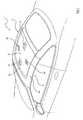
- Fig. 1 shows a first embodiment of the invention a perspective view of a roof area of a vehicle using a Body exterior component according to the invention constructed is
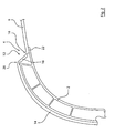
- Fig. 2 is a sectional view through a side Roof frame and part of the adjoining Body outer component of the first embodiment 1 shows
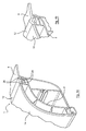
- Fig. 3 shows a second embodiment based on a Similar view as Fig. 1 shows
- Fig. 4a is a perspective sectional view through a side roof frame in the second embodiment 3 shows
- Fig. 4b a portion of Fig. 4a in one shows deformed condition
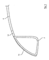
- FIG. 5 based on a schematic sectional view a side roof frame, similar to FIGS. 2 and 4, a another embodiment with a gas pressure process manufactured plastic carrier shows.
- a roof element 1 is formed by an exterior body component according to the invention and is detachably arranged on the body, so that the Roof element is removable for use of the motor vehicle as a Targa vehicle.
- the roof element can also be part of a movable roof of a convertible vehicle or can be fixed to the body.
- the roof element 1 is injection molded made of thermoplastic.
- thermoplastic thermoplastic
- various plastics in an injection mold with different properties to one common component can be combined. Is too it is possible to deposit such as Slides to create Use surface structures.
- the exemplary embodiment is made of plastic Roof element 1 on a metallic support structure in Form of a metallic base support 2 mounted is designed as an all-round frame and the Stiffness of the roof element 1 or Body exterior component supplies.
- the roof element 1 has one of a circumferential Edge area 4 enclosed inner area 6, the mainly due to the temperature in all directions and especially within its extension level expands and contracts lying directions, whereby as essential, to be compensated Expansion directions the longitudinal direction (arrows 8) and the transverse direction (arrows 10) are indicated in Fig. 1.
- the inner region 6 surrounds the side and front and is therefore U-shaped overall is configured. Outside of that Strain compensation element 12 closes one Outer roof skin 14 made of thermoplastic material, which is also configured essentially U-shaped and runs along the base support 2, on which they is attached or on which it rests (Fig. 2).
- Fig. 2 explains the structure and operation of the Roof element according to the invention 1.
- the inner region 6 is over a first film hinge 16 with a Intermediate area 18 connected, which in turn via a second film hinge 18 with the outer roof skin 14 connected is.
- the two film hinges 16, 20 are in the arranged substantially parallel to each other, the Intermediate area 18 a substantially constant Width (transverse dimension with respect to the direction of extension the film hinges 16, 20), and are in arranged in opposite directions, so that there is an approximately Z-shaped configuration of Roof outer skin 14, intermediate area 18 and inner area 6 results.
- the outer roof skin is 14, from the side to the Strain compensation element 12 adjoining areas of the roof, on the base beams 2, which as circumferential frame are formed.
- the basic carrier 2 or the frame can be made of metal or plastic be made, as explained below will be.
- the inner region 6, which in FIG. 2 only is indicated, can be with reinforcing ribs or other reinforcing elements, and he can with its lateral edge areas on the Base carrier 2 rest, as shown in Fig. 2 is.
- Exterior body component from interior area 6 Expansion compensation element 12 and outer roof skin 14, the are integrally connected.
- body exterior component only from integral interconnected interior and Elongation compensation element exist in a more suitable Way would be attached to a support structure.
- FIG. 3 and 4 illustrate another embodiment of the Invention, wherein in Fig. 3 a situation similar to 1, namely a roof element 1, whose interior 6 over a Expansion compensation element 12 with a surrounding one Roof outer skin 14 is connected.
- the expansion compensation element 12 extends rectangular, i.e. closed by that closed interior 6 around, the Roof outer skin 14 closed around that Expansion compensation element 12 runs around.
- this can cause strains of the inner region 6 in all directions, in particular in the longitudinal direction 8 and transverse direction 10, be balanced.
- the expansion compensation element is 12 in this embodiment in the form of a profiled Strip made of elastic, thermoplastic essentially in one plane with the inner region 6 and the roof outer skin 14 adjoining the outside educated.
- Outer roof skin 14, Expansion compensation element 12 and inner region 6 are in the Two-component injection molding process as one continuous component formed, the Roof outer skin 14 with an additionally inserted film appears black on the outside.
- the interior 6 can be transparent.
- the inner area 6 is compared to the elastic Plastic of the expansion compensation element 12 from one essentially made of rigid plastic and in its edge area 4, on which the one-piece connection to the expansion compensation element 12, on a Supported 22 of the base support 2.
- the profiled strain compensation element 12 has two Flange sections 24 with which it is flange-like Projections 26 of the base support 2 engages under, whereby the roof element 1 is held on the base support 2.
- Fig. 5 explains an even more integrated Structure of a plastic outer component according to the invention 1, where not just a roof element, but in addition, a base support 2 made of plastic is, preferably base carrier and roof element in one and the same injection molding tool are manufactured and to generate the basic support (hollow profile) Internal gas pressure method is applied.
- a base support 2 made of plastic is, preferably base carrier and roof element in one and the same injection molding tool are manufactured and to generate the basic support (hollow profile) Internal gas pressure method is applied.
- Those Areas corresponding to the roof skin described above 14 can in this case be used as thermoplastic film (decor) into the injection mold introduced and integral with the base support 2 get connected.
Landscapes
- Engineering & Computer Science (AREA)
- Chemical & Material Sciences (AREA)
- Combustion & Propulsion (AREA)
- Transportation (AREA)
- Mechanical Engineering (AREA)
- Architecture (AREA)
- Structural Engineering (AREA)
- Body Structure For Vehicles (AREA)
- Injection Moulding Of Plastics Or The Like (AREA)
- Table Devices Or Equipment (AREA)
- Sealing Battery Cases Or Jackets (AREA)
- Insulated Conductors (AREA)
Abstract
Description
Dachelement zur Nutzung des Kraftfahrzeug als Targafahrzeug entfernbar ist. Alternativ kann das Dachelement auch Teil eines beweglichen Dachs eines Cabriolet-Fahrzeugs oder fest mit der Karosserie verbunden sein.
- 1
- Dachelement (Karossieaußenbauteil)
- 2
- Grundträger (Trägerstruktur)
- 4
- Randbereich
- 6
- Innenbereich
- 8
- Pfeil (Längsausdehnung)
- 10
- Pfeil (Querausdehnung)
- 12
- Dehnungsausgleichselement
- 14
- Dachaußenhaut
- 16
- erstes Filmscharnier
- 18
- Zwischenbereich
- 20
- zweites Filmscharnier
- 22
- Auflage (von 2)
- 24
- Flanschabschnitt (von 12)
- 26
- Flanschabschnitt (von 2)
Claims (19)
- Karosserieaußenbauteil aus Kunststoff zur Befestigung an einer Tragstruktur (2), mit einem Innenbereich (6) und einem daran angrenzenden Randbereich (4), wobei ein Dehnungsausgleichselement (12) zumindest entlang eines Teilabschnitts des Randbereichs (4) angeordnet und integral damit verbunden ist.
- Karosserieaußenbauteil nach Anspruch 1, dadurch gekennzeichnet, daß das Dehnungsausgleichselement (12) einstückig mit dem Innenbereich (6) verbunden ist.
- Karosserieaußenbauteil nach Anspruch 1, dadurch gekennzeichnet, daß das Dehnungsausgleichselement (12) formschlüssig und ggf. zugfest mit dem Innenbereich (6) verbunden ist, insbesondere durch eine ineinandergreifende Profilierung.
- Karosserieaußenbauteil nach einem der vorangehenden Ansprüche, dadurch gekennzeichnet, daß das Dehnungsausgleichselement (12) parallel zu dem Randbereich (4) angeordnet ist.
- Karosserieaußenbauteil nach einem der vorangehenden Ansprüche, dadurch gekennzeichnet, daß das Dehnungsausgleichselement (12) geschlossen umlaufend entlang des gesamten Randbereichs (4) angeordnet ist.
- Karosserieaußenbauteil nach einem der vorangehenden Ansprüche, dadurch gekennzeichnet, daß das Dehnungsausgleichselement (12) mindestens an zwei Randabschnitten angeordnet ist, die nicht parallel zueinander verlaufen.
- Karosserieaußenbauteil nach Anspruch 1 oder 2, dadurch gekennzeichnet, daß das Karossieraußenbauteil im Zweikomponenten-Spritzgießverfahren hergestellt ist.
- Karosserieaußenbauteil nach einem der vorangehenden Ansprüche, dadurch gekennzeichnet, daß das Karosserieaußenbauteil im Gasinnendruck-Verfahren hergestellt ist.
- Karosserieaußenbauteil nach einem der vorangehenden Ansprüche, dadurch gekennzeichnet, daß das Dehnungsausgleichselement (12) aus einem elastischen Kunststoff besteht.
- Karosserieaußenbauteil nach einem der vorangehenden Ansprüche, dadurch gekennzeichnet, daß das Dehnungsausgleichselement (12) zwei in einem Abstand verlaufende, in entgegengesetzten Richtungen abknickende Filmscharniere (16, 20) aufweist, durch die ein Absatz gebildet wird.
- Karosserieaußenbauteil nach einem der vorangehenden Ansprüche, dadurch gekennzeichnet, daß das Dehnungsausgleichselement (12) an der Tragstruktur (2) abgestützt ist.
- Karosserieaußenbauteil nach einem der vorangehenden Ansprüche, dadurch gekennzeichnet, daß der Innenbereich (6) an der Tragstruktur (2) abgestützt ist.
- Karosserieaußenbauteil nach einem der vorangehenden Ansprüche, dadurch gekennzeichnet, daß das Karosserieaußenbauteil zusammen mit der Tragstruktur in einem Werkzeug hergestellt ist.
- Karrosserieaußenbauteil nach einem der vorangehenden Ansprüche, dadurch gekennzeichnet, daß die Tragstruktur im Gasinnendruck-Verfahren einstückig mit dem Karosserieaußenbauteil hergestellt ist.
- Karosserieaußenbauteil nach einem der vorangehenden Ansprüche, dadurch gekennzeichnet, daß der Innenbereich des Karosserieaußenbauteils mit einem durchsichtigen Kunststoff versehen ist.
- Karosserieaußenbauteil nach einem der vorangehenden Ansprüche, dadurch gekennzeichnet, daß es sich um ein Dachelement (1) handelt.
- Karosserieaußenbauteil nach einem der vorangehenden Ansprüche, dadurch gekennzeichnet, daß das Dehnungsausgleichselement (12) zwischen dem Innenbereich (6) und einem Außenbereich (14) angeordnet ist.
- Fahrzeug mit einem Karosserieaußenbauteil (1) nach einem der vorangehenden Ansprüche.
- Fahrzeug nach Anspruch 17, dadurch gekennzeichnet, daß das Karosserieaußenbauteil als Dachelement (1) ausgebildet ist, welches entfernbar oder beweglich an einer Karosserie des Fahrzeugs angeordnet ist.
Applications Claiming Priority (2)
| Application Number | Priority Date | Filing Date | Title |
|---|---|---|---|
| DE10320438A DE10320438A1 (de) | 2003-05-08 | 2003-05-08 | Karosserieaußenbauteil aus Kunststoff |
| DE10320438 | 2003-05-08 |
Publications (3)
| Publication Number | Publication Date |
|---|---|
| EP1475296A2 true EP1475296A2 (de) | 2004-11-10 |
| EP1475296A3 EP1475296A3 (de) | 2005-05-11 |
| EP1475296B1 EP1475296B1 (de) | 2007-06-27 |
Family
ID=32981268
Family Applications (1)
| Application Number | Title | Priority Date | Filing Date |
|---|---|---|---|
| EP04010027A Expired - Lifetime EP1475296B1 (de) | 2003-05-08 | 2004-04-28 | Karosserieaussenbauteil aus Kunststoff |
Country Status (3)
| Country | Link |
|---|---|
| EP (1) | EP1475296B1 (de) |
| AT (1) | ATE365665T1 (de) |
| DE (2) | DE10320438A1 (de) |
Cited By (2)
| Publication number | Priority date | Publication date | Assignee | Title |
|---|---|---|---|---|
| WO2006103355A1 (fr) * | 2005-03-30 | 2006-10-05 | Compagnie Plastic Omnium | Assemblage d'elements de carrosserie de vehicule automobile et procede de montage de cet assemblage sur le vehicule automobile |
| CN109515136A (zh) * | 2018-10-31 | 2019-03-26 | 北京长城华冠汽车科技股份有限公司 | 顶盖外板和汽车 |
Families Citing this family (1)
| Publication number | Priority date | Publication date | Assignee | Title |
|---|---|---|---|---|
| DE102005033351A1 (de) * | 2005-07-16 | 2007-01-18 | Volkswagen Ag | Herstellung von Kunststoffbaugruppen mit Dehnungselementen |
Citations (1)
| Publication number | Priority date | Publication date | Assignee | Title |
|---|---|---|---|---|
| DE19805884C1 (de) | 1998-02-13 | 1999-07-29 | Audi Ag | Karosserieaußenbauteil |
Family Cites Families (5)
| Publication number | Priority date | Publication date | Assignee | Title |
|---|---|---|---|---|
| FR2038789A5 (de) * | 1969-03-28 | 1971-01-08 | Peugeot & Renault | |
| JPS62194980A (ja) * | 1986-02-19 | 1987-08-27 | Mazda Motor Corp | 自動車用プラスチツクル−フの取付構造 |
| DE10023727C2 (de) * | 2000-05-17 | 2002-10-17 | Webasto Vehicle Sys Int Gmbh | Kunststoff-Fahrzeugdach zur Aufnahme eines Lasttragaufbaus |
| DE10158955A1 (de) * | 2001-12-03 | 2003-06-18 | Webasto Vehicle Sys Int Gmbh | Verbundbauteil für Fahrzeugkarosserien und Fahrzeug mit einem derartigen Verbundbauteil |
| DE10163709B4 (de) * | 2001-12-21 | 2006-05-24 | Arvinmeritor Gmbh | Modulartiges Fahrzeugdach |
-
2003
- 2003-05-08 DE DE10320438A patent/DE10320438A1/de not_active Withdrawn
-
2004
- 2004-04-28 AT AT04010027T patent/ATE365665T1/de not_active IP Right Cessation
- 2004-04-28 EP EP04010027A patent/EP1475296B1/de not_active Expired - Lifetime
- 2004-04-28 DE DE502004004167T patent/DE502004004167D1/de not_active Expired - Lifetime
Patent Citations (1)
| Publication number | Priority date | Publication date | Assignee | Title |
|---|---|---|---|---|
| DE19805884C1 (de) | 1998-02-13 | 1999-07-29 | Audi Ag | Karosserieaußenbauteil |
Cited By (5)
| Publication number | Priority date | Publication date | Assignee | Title |
|---|---|---|---|---|
| WO2006103355A1 (fr) * | 2005-03-30 | 2006-10-05 | Compagnie Plastic Omnium | Assemblage d'elements de carrosserie de vehicule automobile et procede de montage de cet assemblage sur le vehicule automobile |
| FR2883833A1 (fr) * | 2005-03-30 | 2006-10-06 | Plastic Omnium Cie | Assemblage d'elements de carrosserie de vehicule automobile et procede de montage de cet assemblage sur le vehicule automobile |
| CN101189146B (zh) * | 2005-03-30 | 2010-12-29 | 全塑胶公司 | 汽车车身元件的组件及将该组件安装到汽车上的方法 |
| CN109515136A (zh) * | 2018-10-31 | 2019-03-26 | 北京长城华冠汽车科技股份有限公司 | 顶盖外板和汽车 |
| CN109515136B (zh) * | 2018-10-31 | 2020-09-29 | 北京长城华冠汽车科技股份有限公司 | 顶盖外板和汽车 |
Also Published As
| Publication number | Publication date |
|---|---|
| EP1475296A3 (de) | 2005-05-11 |
| EP1475296B1 (de) | 2007-06-27 |
| ATE365665T1 (de) | 2007-07-15 |
| DE10320438A1 (de) | 2004-12-02 |
| DE502004004167D1 (de) | 2007-08-09 |
Similar Documents
| Publication | Publication Date | Title |
|---|---|---|
| EP1088749B1 (de) | Fahrzeugdach | |
| EP1914097B1 (de) | Rahmen für ein Kraftfahrzeugdach | |
| DE102009040901B4 (de) | Verfahren zum Herstellen von Tragstrukturen in Kraftfahrzeugen | |
| DE69409432T2 (de) | Scheibenführung für verschiebbare Fahrzeugscheiben | |
| EP0524447B1 (de) | Fenstereinfassrahmen, insbesondere für Fahrzeuge | |
| EP1448427A1 (de) | Moduldach für ein kraftfahrzeug und verfahren zu seiner montage | |
| DE102019117112A1 (de) | Hybrid-türmodul | |
| EP1176044B1 (de) | Verbundbauteil für Fahrzeugkarosserien sowie Verfahren und Vorrichtung für dessen Herstellung | |
| DE102016000606A1 (de) | Fahrzeugtür | |
| DE102006012699B4 (de) | Glasfaser verstärkte Struktur des Innenraums eines Kraftfahrzeuges | |
| EP3580077A1 (de) | Dichtungselement mit verblendleiste | |
| DE602005005956T2 (de) | Metall- und kunststoffverbundstruktur, insbesondere für die vorderseite eines kraftfahrzeugs | |
| DE10116593B4 (de) | Fahrzeugdach | |
| DE19727010A1 (de) | Fensterrahmenmodul zur Herstellung von Kraftfahrzeugtüren | |
| EP1475296B1 (de) | Karosserieaussenbauteil aus Kunststoff | |
| DE10135406B4 (de) | Fahrzeugdach mit einer Dachöffnung | |
| DE102017216430A1 (de) | Bauteilsystem zur Fixierung eines Verkleidungsteils und Kraftfahrzeug | |
| DE3241652A1 (de) | Fahrzeugaufbau mit fenster | |
| EP2366606B1 (de) | Dachblende | |
| DE69820403T2 (de) | Neue Kraftfahrzeugtürrahmen und Herstellungsverfahren | |
| DE3800262A1 (de) | Dichtleiste | |
| DE102015015750B3 (de) | Wasserfangleiste zur Anordnung an einer A-Säule eines Kraftfahrzeugs, Kraftfahrzeug und Verfahren zum Fertigen einer Wasserfangleiste | |
| DE102016200179A1 (de) | Haltestruktur zur Befestigung und Ausrichtung einer hinteren Stoßfängerverkleidung sowie Verfahren zur Montage einer hinteren Stoßfängerverkleidung an einem Kraftfahrzeug | |
| EP3118037B1 (de) | Fensterführungsschiene | |
| DE102012023326A1 (de) | Flügelelement, insbesondere Klappe, für eine Personenkraftwagenkarosserie |
Legal Events
| Date | Code | Title | Description |
|---|---|---|---|
| PUAI | Public reference made under article 153(3) epc to a published international application that has entered the european phase |
Free format text: ORIGINAL CODE: 0009012 |
|
| AK | Designated contracting states |
Kind code of ref document: A2 Designated state(s): AT BE BG CH CY CZ DE DK EE ES FI FR GB GR HU IE IT LI LU MC NL PL PT RO SE SI SK TR |
|
| AX | Request for extension of the european patent |
Extension state: AL HR LT LV MK |
|
| PUAL | Search report despatched |
Free format text: ORIGINAL CODE: 0009013 |
|
| AK | Designated contracting states |
Kind code of ref document: A3 Designated state(s): AT BE BG CH CY CZ DE DK EE ES FI FR GB GR HU IE IT LI LU MC NL PL PT RO SE SI SK TR |
|
| AX | Request for extension of the european patent |
Extension state: AL HR LT LV MK |
|
| RIC1 | Information provided on ipc code assigned before grant |
Ipc: 7B 62D 29/04 A Ipc: 7B 62D 25/06 B |
|
| 17P | Request for examination filed |
Effective date: 20050630 |
|
| AKX | Designation fees paid |
Designated state(s): AT BE BG CH CY CZ DE DK EE ES FI FR GB GR HU IE IT LI LU MC NL PL PT RO SE SI SK TR |
|
| GRAP | Despatch of communication of intention to grant a patent |
Free format text: ORIGINAL CODE: EPIDOSNIGR1 |
|
| GRAS | Grant fee paid |
Free format text: ORIGINAL CODE: EPIDOSNIGR3 |
|
| GRAA | (expected) grant |
Free format text: ORIGINAL CODE: 0009210 |
|
| AK | Designated contracting states |
Kind code of ref document: B1 Designated state(s): AT BE BG CH CY CZ DE DK EE ES FI FR GB GR HU IE IT LI LU MC NL PL PT RO SE SI SK TR |
|
| REG | Reference to a national code |
Ref country code: GB Ref legal event code: FG4D Free format text: NOT ENGLISH |
|
| REG | Reference to a national code |
Ref country code: CH Ref legal event code: EP |
|
| REG | Reference to a national code |
Ref country code: IE Ref legal event code: FG4D Free format text: LANGUAGE OF EP DOCUMENT: GERMAN |
|
| REF | Corresponds to: |
Ref document number: 502004004167 Country of ref document: DE Date of ref document: 20070809 Kind code of ref document: P |
|
| GBT | Gb: translation of ep patent filed (gb section 77(6)(a)/1977) |
Effective date: 20070808 |
|
| PG25 | Lapsed in a contracting state [announced via postgrant information from national office to epo] |
Ref country code: SE Free format text: LAPSE BECAUSE OF FAILURE TO SUBMIT A TRANSLATION OF THE DESCRIPTION OR TO PAY THE FEE WITHIN THE PRESCRIBED TIME-LIMIT Effective date: 20070927 |
|
| ET | Fr: translation filed | ||
| PG25 | Lapsed in a contracting state [announced via postgrant information from national office to epo] |
Ref country code: PL Free format text: LAPSE BECAUSE OF FAILURE TO SUBMIT A TRANSLATION OF THE DESCRIPTION OR TO PAY THE FEE WITHIN THE PRESCRIBED TIME-LIMIT Effective date: 20070627 |
|
| NLV1 | Nl: lapsed or annulled due to failure to fulfill the requirements of art. 29p and 29m of the patents act | ||
| REG | Reference to a national code |
Ref country code: IE Ref legal event code: FD4D |
|
| PG25 | Lapsed in a contracting state [announced via postgrant information from national office to epo] |
Ref country code: SI Free format text: LAPSE BECAUSE OF FAILURE TO SUBMIT A TRANSLATION OF THE DESCRIPTION OR TO PAY THE FEE WITHIN THE PRESCRIBED TIME-LIMIT Effective date: 20070627 Ref country code: CZ Free format text: LAPSE BECAUSE OF FAILURE TO SUBMIT A TRANSLATION OF THE DESCRIPTION OR TO PAY THE FEE WITHIN THE PRESCRIBED TIME-LIMIT Effective date: 20070627 Ref country code: IE Free format text: LAPSE BECAUSE OF FAILURE TO SUBMIT A TRANSLATION OF THE DESCRIPTION OR TO PAY THE FEE WITHIN THE PRESCRIBED TIME-LIMIT Effective date: 20070627 Ref country code: NL Free format text: LAPSE BECAUSE OF FAILURE TO SUBMIT A TRANSLATION OF THE DESCRIPTION OR TO PAY THE FEE WITHIN THE PRESCRIBED TIME-LIMIT Effective date: 20070627 Ref country code: PT Free format text: LAPSE BECAUSE OF FAILURE TO SUBMIT A TRANSLATION OF THE DESCRIPTION OR TO PAY THE FEE WITHIN THE PRESCRIBED TIME-LIMIT Effective date: 20071127 Ref country code: ES Free format text: LAPSE BECAUSE OF FAILURE TO SUBMIT A TRANSLATION OF THE DESCRIPTION OR TO PAY THE FEE WITHIN THE PRESCRIBED TIME-LIMIT Effective date: 20071008 Ref country code: BG Free format text: LAPSE BECAUSE OF FAILURE TO SUBMIT A TRANSLATION OF THE DESCRIPTION OR TO PAY THE FEE WITHIN THE PRESCRIBED TIME-LIMIT Effective date: 20070927 |
|
| PG25 | Lapsed in a contracting state [announced via postgrant information from national office to epo] |
Ref country code: SK Free format text: LAPSE BECAUSE OF FAILURE TO SUBMIT A TRANSLATION OF THE DESCRIPTION OR TO PAY THE FEE WITHIN THE PRESCRIBED TIME-LIMIT Effective date: 20070627 |
|
| PG25 | Lapsed in a contracting state [announced via postgrant information from national office to epo] |
Ref country code: DK Free format text: LAPSE BECAUSE OF FAILURE TO SUBMIT A TRANSLATION OF THE DESCRIPTION OR TO PAY THE FEE WITHIN THE PRESCRIBED TIME-LIMIT Effective date: 20070627 Ref country code: GR Free format text: LAPSE BECAUSE OF FAILURE TO SUBMIT A TRANSLATION OF THE DESCRIPTION OR TO PAY THE FEE WITHIN THE PRESCRIBED TIME-LIMIT Effective date: 20070928 |
|
| PLBE | No opposition filed within time limit |
Free format text: ORIGINAL CODE: 0009261 |
|
| STAA | Information on the status of an ep patent application or granted ep patent |
Free format text: STATUS: NO OPPOSITION FILED WITHIN TIME LIMIT |
|
| PG25 | Lapsed in a contracting state [announced via postgrant information from national office to epo] |
Ref country code: RO Free format text: LAPSE BECAUSE OF FAILURE TO SUBMIT A TRANSLATION OF THE DESCRIPTION OR TO PAY THE FEE WITHIN THE PRESCRIBED TIME-LIMIT Effective date: 20070627 |
|
| 26N | No opposition filed |
Effective date: 20080328 |
|
| BERE | Be: lapsed |
Owner name: WILHELM KARMANN G.M.B.H. Effective date: 20080430 |
|
| PG25 | Lapsed in a contracting state [announced via postgrant information from national office to epo] |
Ref country code: MC Free format text: LAPSE BECAUSE OF NON-PAYMENT OF DUE FEES Effective date: 20080430 |
|
| REG | Reference to a national code |
Ref country code: CH Ref legal event code: PL |
|
| PG25 | Lapsed in a contracting state [announced via postgrant information from national office to epo] |
Ref country code: CH Free format text: LAPSE BECAUSE OF NON-PAYMENT OF DUE FEES Effective date: 20080430 Ref country code: EE Free format text: LAPSE BECAUSE OF FAILURE TO SUBMIT A TRANSLATION OF THE DESCRIPTION OR TO PAY THE FEE WITHIN THE PRESCRIBED TIME-LIMIT Effective date: 20070627 Ref country code: LI Free format text: LAPSE BECAUSE OF NON-PAYMENT OF DUE FEES Effective date: 20080430 |
|
| PG25 | Lapsed in a contracting state [announced via postgrant information from national office to epo] |
Ref country code: FI Free format text: LAPSE BECAUSE OF FAILURE TO SUBMIT A TRANSLATION OF THE DESCRIPTION OR TO PAY THE FEE WITHIN THE PRESCRIBED TIME-LIMIT Effective date: 20070627 |
|
| PG25 | Lapsed in a contracting state [announced via postgrant information from national office to epo] |
Ref country code: BE Free format text: LAPSE BECAUSE OF NON-PAYMENT OF DUE FEES Effective date: 20080430 |
|
| PG25 | Lapsed in a contracting state [announced via postgrant information from national office to epo] |
Ref country code: CY Free format text: LAPSE BECAUSE OF FAILURE TO SUBMIT A TRANSLATION OF THE DESCRIPTION OR TO PAY THE FEE WITHIN THE PRESCRIBED TIME-LIMIT Effective date: 20070627 |
|
| PG25 | Lapsed in a contracting state [announced via postgrant information from national office to epo] |
Ref country code: AT Free format text: LAPSE BECAUSE OF NON-PAYMENT OF DUE FEES Effective date: 20080428 |
|
| PG25 | Lapsed in a contracting state [announced via postgrant information from national office to epo] |
Ref country code: LU Free format text: LAPSE BECAUSE OF NON-PAYMENT OF DUE FEES Effective date: 20080428 Ref country code: HU Free format text: LAPSE BECAUSE OF FAILURE TO SUBMIT A TRANSLATION OF THE DESCRIPTION OR TO PAY THE FEE WITHIN THE PRESCRIBED TIME-LIMIT Effective date: 20071228 |
|
| PG25 | Lapsed in a contracting state [announced via postgrant information from national office to epo] |
Ref country code: TR Free format text: LAPSE BECAUSE OF FAILURE TO SUBMIT A TRANSLATION OF THE DESCRIPTION OR TO PAY THE FEE WITHIN THE PRESCRIBED TIME-LIMIT Effective date: 20070627 |
|
| PGFP | Annual fee paid to national office [announced via postgrant information from national office to epo] |
Ref country code: IT Payment date: 20130429 Year of fee payment: 10 |
|
| PG25 | Lapsed in a contracting state [announced via postgrant information from national office to epo] |
Ref country code: IT Free format text: LAPSE BECAUSE OF NON-PAYMENT OF DUE FEES Effective date: 20140428 |
|
| REG | Reference to a national code |
Ref country code: FR Ref legal event code: PLFP Year of fee payment: 12 |
|
| REG | Reference to a national code |
Ref country code: FR Ref legal event code: PLFP Year of fee payment: 13 |
|
| REG | Reference to a national code |
Ref country code: DE Ref legal event code: R082 Ref document number: 502004004167 Country of ref document: DE Representative=s name: KRONTHALER, SCHMIDT & COLL. PATENTANWALTSKANZL, DE Ref country code: DE Ref legal event code: R081 Ref document number: 502004004167 Country of ref document: DE Owner name: WEBASTO SE, DE Free format text: FORMER OWNER: WILHELM KARMANN GMBH, 49084 OSNABRUECK, DE |
|
| REG | Reference to a national code |
Ref country code: FR Ref legal event code: PLFP Year of fee payment: 14 |
|
| REG | Reference to a national code |
Ref country code: GB Ref legal event code: 732E Free format text: REGISTERED BETWEEN 20170511 AND 20170517 |
|
| REG | Reference to a national code |
Ref country code: FR Ref legal event code: PLFP Year of fee payment: 15 |
|
| REG | Reference to a national code |
Ref country code: FR Ref legal event code: TP Owner name: WEBASTO-EDSCHA CABRIO GMBH, DE Effective date: 20180503 |
|
| PGFP | Annual fee paid to national office [announced via postgrant information from national office to epo] |
Ref country code: FR Payment date: 20180424 Year of fee payment: 15 |
|
| PGFP | Annual fee paid to national office [announced via postgrant information from national office to epo] |
Ref country code: GB Payment date: 20180403 Year of fee payment: 15 |
|
| GBPC | Gb: european patent ceased through non-payment of renewal fee |
Effective date: 20190428 |
|
| PG25 | Lapsed in a contracting state [announced via postgrant information from national office to epo] |
Ref country code: GB Free format text: LAPSE BECAUSE OF NON-PAYMENT OF DUE FEES Effective date: 20190428 |
|
| PG25 | Lapsed in a contracting state [announced via postgrant information from national office to epo] |
Ref country code: FR Free format text: LAPSE BECAUSE OF NON-PAYMENT OF DUE FEES Effective date: 20190430 |
|
| PGFP | Annual fee paid to national office [announced via postgrant information from national office to epo] |
Ref country code: DE Payment date: 20230418 Year of fee payment: 20 |
|
| REG | Reference to a national code |
Ref country code: DE Ref legal event code: R071 Ref document number: 502004004167 Country of ref document: DE |