EP1475270A2 - Baugruppe mit einem Lenkrad und einem Gassackmodul - Google Patents
Baugruppe mit einem Lenkrad und einem Gassackmodul Download PDFInfo
- Publication number
- EP1475270A2 EP1475270A2 EP04009844A EP04009844A EP1475270A2 EP 1475270 A2 EP1475270 A2 EP 1475270A2 EP 04009844 A EP04009844 A EP 04009844A EP 04009844 A EP04009844 A EP 04009844A EP 1475270 A2 EP1475270 A2 EP 1475270A2
- Authority
- EP
- European Patent Office
- Prior art keywords
- steering wheel
- gas bag
- horn
- bag module
- assembly according
- Prior art date
- Legal status (The legal status is an assumption and is not a legal conclusion. Google has not performed a legal analysis and makes no representation as to the accuracy of the status listed.)
- Withdrawn
Links
Images


Classifications
-
- B—PERFORMING OPERATIONS; TRANSPORTING
- B60—VEHICLES IN GENERAL
- B60R—VEHICLES, VEHICLE FITTINGS, OR VEHICLE PARTS, NOT OTHERWISE PROVIDED FOR
- B60R21/00—Arrangements or fittings on vehicles for protecting or preventing injuries to occupants or pedestrians in case of accidents or other traffic risks
- B60R21/02—Occupant safety arrangements or fittings, e.g. crash pads
- B60R21/16—Inflatable occupant restraints or confinements designed to inflate upon impact or impending impact, e.g. air bags
- B60R21/20—Arrangements for storing inflatable members in their non-use or deflated condition; Arrangement or mounting of air bag modules or components
- B60R21/203—Arrangements for storing inflatable members in their non-use or deflated condition; Arrangement or mounting of air bag modules or components in steering wheels or steering columns
- B60R21/2035—Arrangements for storing inflatable members in their non-use or deflated condition; Arrangement or mounting of air bag modules or components in steering wheels or steering columns using modules containing inflator, bag and cover attachable to the steering wheel as a complete sub-unit
- B60R21/2037—Arrangements for storing inflatable members in their non-use or deflated condition; Arrangement or mounting of air bag modules or components in steering wheels or steering columns using modules containing inflator, bag and cover attachable to the steering wheel as a complete sub-unit the module or a major component thereof being yieldably mounted, e.g. for actuating the horn switch or for protecting the driver in a non-deployment situation
-
- B—PERFORMING OPERATIONS; TRANSPORTING
- B60—VEHICLES IN GENERAL
- B60Q—ARRANGEMENT OF SIGNALLING OR LIGHTING DEVICES, THE MOUNTING OR SUPPORTING THEREOF OR CIRCUITS THEREFOR, FOR VEHICLES IN GENERAL
- B60Q5/00—Arrangement or adaptation of acoustic signal devices
- B60Q5/001—Switches therefor
- B60Q5/003—Switches therefor mounted on the steering wheel
Definitions
- the invention relates to an assembly with a steering wheel and a Airbag module.
- the invention provides a simple assembly that meets these requirements.
- an assembly with a steering wheel and an in a hub area of the steering wheel accommodated gas bag module that for Pressing a horn is movable in the axial direction of the steering wheel, and with at least one restoring element, the at least one elastic section has a restoring force acting against an actuating force for the horn exerts on the gas bag module, the elastic section between one Module housing and a fastening provided in the hub area of the steering wheel.
- the elastic section is firm and not slidable at one end the module housing and at another end with the attachment in the hub area connected and has a contact portion between the ends, the forms an electrical horn contact.
- the elastic section extends in the assembled state of the gas bag module in the steering wheel preferably diagonally between the gas bag module and the Hub area of the steering wheel.
- This arrangement gives e.g. in the Use of a resilient wire as a return element in the event of a deflection of the gas bag module automatically a resetting force. So on spiral springs to be dispensed with.
- the elastic section in a first deflected position in which a first restoring force is generated in contact with a complementary horn contact.
- the assembly of the gas bag module on the steering wheel can be simplified by it is provided that the elastic section in a second deflected position is movable in which a second restoring force is generated which is greater than that first restoring force. Usually in the second deflected position the elastic section be more bent than in the first deflected Position. This arrangement allows one in the second deflected position Snap connection between a fastening element of the gas bag module and to close the steering wheel. This so-called overpressibility of the elastic Section ensures secure locking of fasteners that the gas bag module on the steering wheel, more precisely e.g. to its skeleton.
- the fasteners are preferably compared to the Reset element separate components. Due to the strong restoring force in the second deflected position, the gas bag module is removed after mounting on the steering wheel the mounting position (which corresponds to the second deflected position) in its Normal position moves.
- connection between the elastic section and the gas bag module and / or the steering wheel can be a snap-in connection.
- the fastening of the restoring element in the hub area is preferred of the steering wheel formed by a foamed portion of the steering wheel with which one end of the elastic section can latch.
- both the snap connection for fastening the gas bag module to the steering wheel as also the locking connection for the firm connection of the elastic section of the Reset element with the steering wheel by simply inserting the gas bag module in the hub area of the steering wheel.
- the rest connection here between the elastic section and the foamed section cannot withstand as high forces as the snap-in connection for fastening of the gas bag module.
- the reset element or its elastic section can also on the module housing be locked.
- the end of the module housing fixed is preferred elastic section embedded in the module housing, e.g. by pouring or overmolding. This solution is particularly useful when the module housing consists of plastic.
- the elastic section or sections extend substantially radial. This creates an even restoring force and a low backlash Guided tour without tilting the gas bag module.
- the reset element can e.g. is a one-piece, bent wire.
- the reset element is outside the contact section and of course a corresponding contact to one Horn circuit preferred over the gas bag module or the steering wheel isolated.
- the reset element can perform three functions according to the invention. On the one hand, it generates the restoring force when the horn is actuated second, it can function as a guide for the gas bag module in the axial Fulfill movement of the gas bag module and, thirdly, it preferably forms the half of the horn contacts.
- Figure 1 shows the underside of an airbag module 10, as it is e.g. in one in the Figures 3 to 5 shown steering wheel 12 can be used.
- a receptacle 18 for formed a gas generator 20 in which the gas generator 20 is known Way is fixed.
- a folded gas bag 17 added (see Figure 3).
- each restoring element 22 has two elastic sections 26, each fixed at a first end 27 and immovable with the Module housing 14 are connected.
- the reset elements 22 can be connected to the Module housing 14 may be connected while in the in FIGS. 3 to 5 Gas bag module 10 shown in the module housing 14 specifically by overmolding or encapsulation are embedded.
- the reset elements could also on other suitable ways, e.g. via a forming process with the module housing 14 be firmly connected.
- the reset elements 22 essentially consist of a one-piece, spring wire bent into a corresponding shape.
- the elastic sections 26 of the restoring elements 22 extend essentially radially Direction as long as the gas bag module 10 is not connected to the steering wheel 12.
- Each two of the elastic sections 26 are punctiform Attachment section 28 connected to a second end of each elastic Section forms. If the gas bag module 10 is inserted into the steering wheel 12, run the elastic sections 26 obliquely from the bottom 15 of the module housing 14 to the hub area 13 of the steering wheel 12.
- one of the elastic sections each has 26 on an arcuately curved contact section 30, the one Horn contact forms.
- FIG. 2 shows a variant of the reset element 22, in which the elastic sections 26 run parallel to each other radially outwards and themselves the fastening section 28 perpendicular to the elastic sections 26 extends.
- a contact section 30 on each of the elastic sections 26 trained as a horn contact.
- each of the contact portions 30 may be in contact with complementary ones Horn contacts 32 come here as separate projections on the Underside 15 of the module housing 14 is formed or into the module housing 14 are embedded.
- Horn contacts 32 come here as separate projections on the Underside 15 of the module housing 14 is formed or into the module housing 14 are embedded.
- the horn contacts 30, 32 are known to the person skilled in the art with a Horn circuit not shown connected.
- the horn contacts 30, 32 and Horn circuit are designed so that when touching a contact section 30 the horn sounds with a horn contact 32.
- the fastening sections 28 are insulated from the free sections 26, all or part (at least in the area of the contact sections 30) are not electrically insulated.
- the reset elements 22 are opposite Module housing 14 electrically isolated. For a plastic one For this, module housing 14 requires no further precautions metallic module housings are known to those skilled in the art electrical insulation. The isolation of the reset elements 22 can e.g. through plastic encapsulation in all areas except the contact sections 30 be realized.
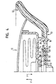
- Figures 3 to 5 show an assembly in which the gas bag module 10 in a hub portion 13 of a steering wheel 12 is inserted.
- the gas bag module 10 is on the locking hook 16 and in the hub area 13 of the Steering wheel 12 arranged steering wheel fixed locking means 38 fixed to the steering wheel 12 connected.
- the locking means 38 here consist of a steering wheel 12 fixed component that can be moved by a certain amount (e.g. a wire) into which the locking hooks 16 engage.
- This connection is like that designed that movement of the airbag module 10 in the vertical direction z (i.e. in the direction of the axis of rotation of the steering wheel) within the steering wheel 12 is without the locking connection 16, 38 is released.
- the fastening sections 28 of the restoring elements 22 are pocket-shaped Attachments 34 connected by foamed sections 36 in Steering wheel interior are formed and receptacles for the fastening sections 28 form.
- the elastic sections 26 of the restoring elements 22 extend at an angle between the gas bag module 10 and the hub area 13 of the steering wheel 12th
- the elastic portions 26 are designed so that the force that a movement of the gas bag module 10 in the axial direction (z direction) opposite is, on the one hand, so large that the gas bag module 10 is not due to vehicle vehicle vibrations is set in motion in the steering wheel 12, on the other hand but is so low that the driver uses the gas bag module 10 to actuate the horn can press down without great effort.
- the gas bag module 10 In the normal position shown in Figure 3, the gas bag module 10 is fixed connected to the steering wheel 12 and the horn is not actuated.
- the elastic Sections 26 are in an undeflected position and none Contact section 30 contacts a complementary horn contact 32.
- the elastic Sections 26, however, have a certain preload, the one spontaneous movement of the gas bag module in the axial direction e.g. owing to Prevents vehicle movements.
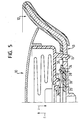
- FIG. 4 shows the assembly from FIG. 3 with the horn actuated.
- the gas bag module 10 was moved as a whole in the axial direction z. This movement causes the elastic portions 26 of the return element 22 in a first position are deflected and have assumed a first curvature. At the same time, the distance between the contact sections 30 and complementary horn contacts 32 reduced so far that the contact sections 30 and the complementary horn contacts 32 come into contact with one another, so that the horn circuit is closed.
- the gas bag module 10 is still as before with the steering wheel 12 via the locking connection 16, 38 and the restoring elements 22 connected.
- the gas bag module 10 is pushed further into the interior of the steering wheel 12, than is necessary to operate the horn.
- the elastic sections 26 of the reset element 22 are deflected into a second Curved position in which they are further deflected and curved more than in the first deflected position to operate the horn, resulting in a stronger one Restoring force as a result in the first deflected position.
- the reset elements 22 can be pushed over, allowing the latching hooks 16 to be securely inserted Bring engagement with the locking means 38 of the steering wheel 12.
- the attachment 34 forms a pivot bearing for the return element 22, in which the cylindrical fastening section 28 into a cylindrical, sectionally open fastening 34 is used (see also 3 to 5) in which the fastening section 28 can rotate (see FIG 5).
- the main load of fastening the gas bag module 10 to the steering wheel 12 in the z direction carries the locking connection 16, 38, while the locking connection 28, 34 between the reset element 22 and the foamed portion 36 only must withstand low forces in the z direction. Fixing the elastic Sections 26 on the steering wheel 12 ensures precise guidance of the movement of the Airbag module 10.
- the direction z is perpendicular to the plane a steering wheel rim 40, ie in the axial direction of the steering wheel 12.
- the invention is also feasible for steering wheels, where the direction of movement The horn is actuated in a different direction.
Abstract
Description
- Figur 1 eine schematische perspektivische Teilansicht eines Gassackmoduls einer erfindungsgemäßen Baugruppe von dessen Unterseite gesehen;
- Figur 2 eine schematische perspektivische Teilansicht eines Modulgehäuses für ein Gassackmodul einer erfindungsgemäßen Baugruppe gemäß einer Variante zu dem in Figur 1 gezeigten Gehäuse;
- Figur 3 eine teilgeschnittene Ansicht einer erfindungsgemäßen Baugruppe in einem Zustand, in dem das Gassackmodul nach Figur 1 oder 2 mit dem Lenkrad verbunden und die Hupe nicht betätigt ist;
- Figur 4 die Baugruppe aus Figur 3 in einem Zustand, in dem das Gassackmodul mit dem Lenkrad verbunden und die Hupe betätigt ist; und
- Figur 5 die Baugruppe aus Figur 3 in einem Zustand, in dem das Gassackmodul gerade mit dem Lenkrad verbunden wird.
Claims (11)
- Baugruppe, mit einem Lenkrad (12) und einem in einem Nabenbereich (13) des Lenkrads (12) aufgenommenen Gassackmodul (10), das zum Betätigen einer Hupe in Achsrichtung (z) des Lenkrads (12) bewegbar ist, und
mit wenigstens einem Rückstellelement (22), das wenigstens einen elastischen Abschnitt (26) aufweist, der eine entgegen einer Betätigungskraft für die Hupe wirkende Rückstellkraft auf das Gassackmodul (10) ausübt, sich zwischen einem Modulgehäuse (14) und einer im Nabenbereich (13) des Lenkrads (12) vorgesehenen Befestigung (34) für das Rückstellelement (22) erstreckt, fest und nicht verschiebbar an einem Ende (27) mit dem Modulgehäuse (14) und an einem anderen Ende (28) mit der Befestigung (34) im Nabenbereich (13) verbunden ist und zwischen den Enden (27, 28) einen Kontaktabschnitt (30) aufweist, der einen elektrischen Hupkontakt bildet. - Baugruppe nach Anspruch 1, dadurch gekennzeichnet, daß sich der elastische Abschnitt (26) schräg zwischen dem Gassackmodul (10) und dem Nabenbereich (13) des Lenkrads (12) erstreckt.
- Baugruppe nach einem der vorhergehenden Ansprüche, dadurch gekennzeichnet, daß der elastische Abschnitt (26) in einer ersten ausgelenkten Position, in der eine erste Rückstellkraft erzeugt wird, in Kontakt mit einem komplementären Hupkontakt (32) ist.
- Baugruppe nach Anspruch 3, dadurch gekennzeichnet, daß der elastische Abschnitt (26) in eine zweite ausgelenkte Position bewegbar ist, in der eine zweite Rückstellkraft erzeugt wird, die größer ist als die erste Rückstellkraft.
- Baugruppe nach Anspruch 4, dadurch gekennzeichnet, daß in der zweiten ausgelenkten Position eine Rastverbindung (16, 38) zwischen einem Befestigungselement (16) des Gassackmoduls (10) und dem Lenkrad (12) geschlossen werden kann.
- Baugruppe nach einem der vorhergehenden Ansprüche, dadurch gekennzeichnet, daß die Verbindung zwischen dem Rückstellelement (22) und dem Gassackmodul (10) und/oder der Befestigung (34) des Rückstellelements (22) im Lenkrad (12) eine Rastverbindung (28, 34) ist.
- Baugruppe nach Anspruch 6, dadurch gekennzeichnet, daß die Befestigung (34) durch einen geschäumten Abschnitt (36) des Lenkrads (12) gebildet ist.
- Baugruppe nach einem der vorhergehenden Ansprüche, dadurch gekennzeichnet, daß die Befestigung (34) als Schwenklager für das Rückstellelement (22) ausgebildet ist.
- Baugruppe nach einem der vorhergehenden Ansprüche, dadurch gekennzeichnet, daß der zum Kontaktabschnitt (30) komplementäre Hupkontakt (32) am Gassackmodul (10) angeordnet ist.
- Baugruppe nach einem der vorhergehenden Ansprüche, dadurch gekennzeichnet, daß das modulgehäusefeste Ende (27) des elastischen Abschnitts (26) in das Modulgehäuse (14) des Gassackmoduls (10) eingebettet ist.
- Baugruppe nach einem der vorhergehenden Ansprüche, dadurch gekennzeichnet, daß der elastische Abschnitt (26) ein sich im wesentlichen radial erstreckender drahtförmiger Körper ist.
Applications Claiming Priority (2)
| Application Number | Priority Date | Filing Date | Title |
|---|---|---|---|
| DE20307096U | 2003-05-07 | ||
| DE20307096U DE20307096U1 (de) | 2003-05-07 | 2003-05-07 | Baugruppe aus einem Lenkrad und einem Gassackmodul |
Publications (2)
| Publication Number | Publication Date |
|---|---|
| EP1475270A2 true EP1475270A2 (de) | 2004-11-10 |
| EP1475270A3 EP1475270A3 (de) | 2005-04-06 |
Family
ID=29225313
Family Applications (1)
| Application Number | Title | Priority Date | Filing Date |
|---|---|---|---|
| EP04009844A Withdrawn EP1475270A3 (de) | 2003-05-07 | 2004-04-26 | Baugruppe mit einem Lenkrad und einem Gassackmodul |
Country Status (3)
| Country | Link |
|---|---|
| US (1) | US20050012311A1 (de) |
| EP (1) | EP1475270A3 (de) |
| DE (1) | DE20307096U1 (de) |
Cited By (5)
| Publication number | Priority date | Publication date | Assignee | Title |
|---|---|---|---|---|
| EP1669255A1 (de) * | 2004-12-10 | 2006-06-14 | Takata Corporation | Hupschalter, Airbag-System und Lenkrad |
| EP1671854A1 (de) * | 2004-12-17 | 2006-06-21 | Takata Corporation | Hupschalter, Airbag-System und Lenkrad |
| EP1671853A1 (de) * | 2004-12-17 | 2006-06-21 | Takata Corporation | Hupschalter, Airbag-System und Lenkrad |
| GB2512892A (en) * | 2013-04-10 | 2014-10-15 | Ford Global Tech Llc | A method and apparatus for attaching a driver airbag module to a steering wheel |
| WO2014191295A1 (de) * | 2013-05-25 | 2014-12-04 | Autoliv Development Ab | Lenkradeinheit |
Families Citing this family (7)
| Publication number | Priority date | Publication date | Assignee | Title |
|---|---|---|---|---|
| US7159897B2 (en) * | 2003-07-21 | 2007-01-09 | Delphi Technologies, Inc. | Isolated ground for horn mechanism |
| DE202009018412U1 (de) * | 2009-02-04 | 2011-09-28 | Takata-Petri Ag | Lenkradbaugruppe für ein Kraftfahrzeug |
| EP2907700B1 (de) * | 2014-02-17 | 2021-07-21 | Dalphi Metal España, S.A. | Hupensystem |
| KR102335527B1 (ko) * | 2017-06-27 | 2021-12-03 | 현대자동차주식회사 | 자동차용 혼 작동 장치 |
| KR102394806B1 (ko) * | 2017-11-29 | 2022-05-04 | 현대자동차주식회사 | 자동차의 혼 작동 장치 |
| KR102505744B1 (ko) * | 2018-02-07 | 2023-03-06 | 현대모비스 주식회사 | 운전석 에어백 장치 |
| KR20240033489A (ko) * | 2022-09-05 | 2024-03-12 | 현대자동차주식회사 | 스티어링휠과, 그 스티어링휠의 댐퍼유닛 |
Citations (6)
| Publication number | Priority date | Publication date | Assignee | Title |
|---|---|---|---|---|
| EP0390029A2 (de) * | 1989-03-27 | 1990-10-03 | Toyoda Gosei Co., Ltd. | Lenkrad-Hupenschaltermechanismus |
| EP0390030A2 (de) * | 1989-03-27 | 1990-10-03 | Toyoda Gosei Co., Ltd. | Lenkrad-Hupenschaltermechanismus |
| US5650600A (en) * | 1995-06-01 | 1997-07-22 | Trw Inc. | Horn switch for air bag module |
| US5738369A (en) * | 1996-10-09 | 1998-04-14 | Breed Automotive Technology, Inc. | Snap-on air bag and horn switch module |
| US6199908B1 (en) * | 1997-01-16 | 2001-03-13 | Toyoda Gosei Co., Ltd. | Steering wheel and horn switch assembly for the steering wheel |
| DE20213908U1 (de) * | 2002-09-09 | 2003-01-30 | Trw Automotive Safety Sys Gmbh | Airbagmodul sowie Baugruppe aus einem Lenkrad und einem Airbagmodul |
Family Cites Families (3)
| Publication number | Priority date | Publication date | Assignee | Title |
|---|---|---|---|---|
| JPH08207783A (ja) * | 1994-12-07 | 1996-08-13 | Toyoda Gosei Co Ltd | ステアリングホイール |
| IT1308842B1 (it) * | 1999-09-24 | 2002-01-11 | Gallino Plasturgia S R L | Dispositivo di azionamento di avvisatore acustico per un volante diazionamento. |
| US6942247B2 (en) * | 2003-03-12 | 2005-09-13 | Delphi Technologies, Inc. | Driver airbag formed contact spring |
-
2003
- 2003-05-07 DE DE20307096U patent/DE20307096U1/de not_active Expired - Lifetime
-
2004
- 2004-04-26 EP EP04009844A patent/EP1475270A3/de not_active Withdrawn
- 2004-05-07 US US10/841,017 patent/US20050012311A1/en not_active Abandoned
Patent Citations (6)
| Publication number | Priority date | Publication date | Assignee | Title |
|---|---|---|---|---|
| EP0390029A2 (de) * | 1989-03-27 | 1990-10-03 | Toyoda Gosei Co., Ltd. | Lenkrad-Hupenschaltermechanismus |
| EP0390030A2 (de) * | 1989-03-27 | 1990-10-03 | Toyoda Gosei Co., Ltd. | Lenkrad-Hupenschaltermechanismus |
| US5650600A (en) * | 1995-06-01 | 1997-07-22 | Trw Inc. | Horn switch for air bag module |
| US5738369A (en) * | 1996-10-09 | 1998-04-14 | Breed Automotive Technology, Inc. | Snap-on air bag and horn switch module |
| US6199908B1 (en) * | 1997-01-16 | 2001-03-13 | Toyoda Gosei Co., Ltd. | Steering wheel and horn switch assembly for the steering wheel |
| DE20213908U1 (de) * | 2002-09-09 | 2003-01-30 | Trw Automotive Safety Sys Gmbh | Airbagmodul sowie Baugruppe aus einem Lenkrad und einem Airbagmodul |
Cited By (5)
| Publication number | Priority date | Publication date | Assignee | Title |
|---|---|---|---|---|
| EP1669255A1 (de) * | 2004-12-10 | 2006-06-14 | Takata Corporation | Hupschalter, Airbag-System und Lenkrad |
| EP1671854A1 (de) * | 2004-12-17 | 2006-06-21 | Takata Corporation | Hupschalter, Airbag-System und Lenkrad |
| EP1671853A1 (de) * | 2004-12-17 | 2006-06-21 | Takata Corporation | Hupschalter, Airbag-System und Lenkrad |
| GB2512892A (en) * | 2013-04-10 | 2014-10-15 | Ford Global Tech Llc | A method and apparatus for attaching a driver airbag module to a steering wheel |
| WO2014191295A1 (de) * | 2013-05-25 | 2014-12-04 | Autoliv Development Ab | Lenkradeinheit |
Also Published As
| Publication number | Publication date |
|---|---|
| DE20307096U1 (de) | 2003-10-09 |
| EP1475270A3 (de) | 2005-04-06 |
| US20050012311A1 (en) | 2005-01-20 |
Similar Documents
| Publication | Publication Date | Title |
|---|---|---|
| EP1197402B1 (de) | Fahrzeuglenkrad | |
| EP1181172B1 (de) | Lenkrad | |
| EP1557852B1 (de) | Fahrzeuglenkrad | |
| WO2013068101A1 (de) | Lenkradeinheit | |
| EP2534015B1 (de) | Sicherheitsanordnung | |
| EP1475270A2 (de) | Baugruppe mit einem Lenkrad und einem Gassackmodul | |
| EP1398227A1 (de) | Airbagmodul sowie Baugruppe aus einem Lenkrad und einem Airbagmodul | |
| EP1716012A1 (de) | Komponente, insbesondere sonnenblende und insbesondere für ein fahrzeug, verfahren zur herstellung einer komponente | |
| EP3116751B1 (de) | Verbinderbauteil zur befestigung eines gassackmoduls an einem lenkrad, set mit einem solchen verbinderbauteil und einer positionierhülse sowie lenkrad, gassackmodul, lenkradbaugruppe und herstellungsverfahren hierfür | |
| EP2509830B1 (de) | Fahrzeuglenkrad | |
| EP1426248B1 (de) | Gassackmodul | |
| DE4117303C2 (de) | Hupenbetätigungseinsatz für ein Lenkrad | |
| EP1410959B1 (de) | Baugruppe mit einem Lenkradgrundkörper und einem Gassackmodul | |
| DE102010008159A1 (de) | Hupenaktivierungseinrichtung | |
| DE60102092T2 (de) | Schaltereinheit für ein Lenkrad in einem Kraftfahrzeug | |
| DE202018104187U1 (de) | Gassackmodul für ein Fahrzeuglenkrad | |
| DE102020115031A1 (de) | Lenkrad, welches ein Gassackmodul aufweist | |
| EP1654142B1 (de) | Gehäuse für ein gassackmodul | |
| EP1145922B1 (de) | Fahrzeuglenkrad mit verschieblich gelagertem Gassackmodul | |
| EP1524151B1 (de) | Lenkradhupenkontakteinheit und Baugruppe | |
| DE102011120490A1 (de) | Anordnung eines Lenkrades und eines mit diesem verbundenen Airbag-Moduls bei einem Kraftfahrzeug | |
| DE102018102755A1 (de) | Gassackmodul, Verfahren zur Herstellung eines Gassackmoduls und Lenkrad | |
| DE202018103190U1 (de) | Hupenbaugruppe für ein Fahrzeuglenkrad | |
| DE102004051434A1 (de) | Gehäuse für ein Gassackmodul | |
| DE10064308C1 (de) | Anordnung bestehend aus einem Träger und einer elektrischen/elektronischen Einheit |
Legal Events
| Date | Code | Title | Description |
|---|---|---|---|
| PUAI | Public reference made under article 153(3) epc to a published international application that has entered the european phase |
Free format text: ORIGINAL CODE: 0009012 |
|
| AK | Designated contracting states |
Kind code of ref document: A2 Designated state(s): AT BE BG CH CY CZ DE DK EE ES FI FR GB GR HU IE IT LI LU MC NL PL PT RO SE SI SK TR |
|
| AX | Request for extension of the european patent |
Extension state: AL HR LT LV MK |
|
| PUAL | Search report despatched |
Free format text: ORIGINAL CODE: 0009013 |
|
| AK | Designated contracting states |
Kind code of ref document: A3 Designated state(s): AT BE BG CH CY CZ DE DK EE ES FI FR GB GR HU IE IT LI LU MC NL PL PT RO SE SI SK TR |
|
| AX | Request for extension of the european patent |
Extension state: AL HR LT LV MK |
|
| RIC1 | Information provided on ipc code assigned before grant |
Ipc: 7B 60R 21/20 B Ipc: 7B 60Q 5/00 A |
|
| 17P | Request for examination filed |
Effective date: 20051006 |
|
| AKX | Designation fees paid |
Designated state(s): DE ES FR IT |
|
| GRAP | Despatch of communication of intention to grant a patent |
Free format text: ORIGINAL CODE: EPIDOSNIGR1 |
|
| STAA | Information on the status of an ep patent application or granted ep patent |
Free format text: STATUS: THE APPLICATION IS DEEMED TO BE WITHDRAWN |
|
| 18D | Application deemed to be withdrawn |
Effective date: 20070111 |