EP1475255A1 - Radführendes Vorderachs-Federbein - Google Patents
Radführendes Vorderachs-Federbein Download PDFInfo
- Publication number
- EP1475255A1 EP1475255A1 EP04006636A EP04006636A EP1475255A1 EP 1475255 A1 EP1475255 A1 EP 1475255A1 EP 04006636 A EP04006636 A EP 04006636A EP 04006636 A EP04006636 A EP 04006636A EP 1475255 A1 EP1475255 A1 EP 1475255A1
- Authority
- EP
- European Patent Office
- Prior art keywords
- damper
- spring
- bearing
- air spring
- seal
- Prior art date
- Legal status (The legal status is an assumption and is not a legal conclusion. Google has not performed a legal analysis and makes no representation as to the accuracy of the status listed.)
- Granted
Links
Images


Classifications
-
- F—MECHANICAL ENGINEERING; LIGHTING; HEATING; WEAPONS; BLASTING
- F16—ENGINEERING ELEMENTS AND UNITS; GENERAL MEASURES FOR PRODUCING AND MAINTAINING EFFECTIVE FUNCTIONING OF MACHINES OR INSTALLATIONS; THERMAL INSULATION IN GENERAL
- F16F—SPRINGS; SHOCK-ABSORBERS; MEANS FOR DAMPING VIBRATION
- F16F9/00—Springs, vibration-dampers, shock-absorbers, or similarly-constructed movement-dampers using a fluid or the equivalent as damping medium
- F16F9/02—Springs, vibration-dampers, shock-absorbers, or similarly-constructed movement-dampers using a fluid or the equivalent as damping medium using gas only or vacuum
- F16F9/04—Springs, vibration-dampers, shock-absorbers, or similarly-constructed movement-dampers using a fluid or the equivalent as damping medium using gas only or vacuum in a chamber with a flexible wall
- F16F9/0472—Springs, vibration-dampers, shock-absorbers, or similarly-constructed movement-dampers using a fluid or the equivalent as damping medium using gas only or vacuum in a chamber with a flexible wall characterised by comprising a damping device
-
- B—PERFORMING OPERATIONS; TRANSPORTING
- B60—VEHICLES IN GENERAL
- B60G—VEHICLE SUSPENSION ARRANGEMENTS
- B60G15/00—Resilient suspensions characterised by arrangement, location or type of combined spring and vibration damper, e.g. telescopic type
- B60G15/08—Resilient suspensions characterised by arrangement, location or type of combined spring and vibration damper, e.g. telescopic type having fluid spring
- B60G15/12—Resilient suspensions characterised by arrangement, location or type of combined spring and vibration damper, e.g. telescopic type having fluid spring and fluid damper
- B60G15/14—Resilient suspensions characterised by arrangement, location or type of combined spring and vibration damper, e.g. telescopic type having fluid spring and fluid damper the damper being connected to the stub axle and the spring being arranged around the damper
-
- F—MECHANICAL ENGINEERING; LIGHTING; HEATING; WEAPONS; BLASTING
- F16—ENGINEERING ELEMENTS AND UNITS; GENERAL MEASURES FOR PRODUCING AND MAINTAINING EFFECTIVE FUNCTIONING OF MACHINES OR INSTALLATIONS; THERMAL INSULATION IN GENERAL
- F16F—SPRINGS; SHOCK-ABSORBERS; MEANS FOR DAMPING VIBRATION
- F16F9/00—Springs, vibration-dampers, shock-absorbers, or similarly-constructed movement-dampers using a fluid or the equivalent as damping medium
- F16F9/02—Springs, vibration-dampers, shock-absorbers, or similarly-constructed movement-dampers using a fluid or the equivalent as damping medium using gas only or vacuum
- F16F9/04—Springs, vibration-dampers, shock-absorbers, or similarly-constructed movement-dampers using a fluid or the equivalent as damping medium using gas only or vacuum in a chamber with a flexible wall
- F16F9/0418—Springs, vibration-dampers, shock-absorbers, or similarly-constructed movement-dampers using a fluid or the equivalent as damping medium using gas only or vacuum in a chamber with a flexible wall having a particular shape, e.g. annular, spherical, tube-like
- F16F9/0427—Springs, vibration-dampers, shock-absorbers, or similarly-constructed movement-dampers using a fluid or the equivalent as damping medium using gas only or vacuum in a chamber with a flexible wall having a particular shape, e.g. annular, spherical, tube-like toroidal
-
- F—MECHANICAL ENGINEERING; LIGHTING; HEATING; WEAPONS; BLASTING
- F16—ENGINEERING ELEMENTS AND UNITS; GENERAL MEASURES FOR PRODUCING AND MAINTAINING EFFECTIVE FUNCTIONING OF MACHINES OR INSTALLATIONS; THERMAL INSULATION IN GENERAL
- F16F—SPRINGS; SHOCK-ABSORBERS; MEANS FOR DAMPING VIBRATION
- F16F9/00—Springs, vibration-dampers, shock-absorbers, or similarly-constructed movement-dampers using a fluid or the equivalent as damping medium
- F16F9/06—Springs, vibration-dampers, shock-absorbers, or similarly-constructed movement-dampers using a fluid or the equivalent as damping medium using both gas and liquid
- F16F9/08—Springs, vibration-dampers, shock-absorbers, or similarly-constructed movement-dampers using a fluid or the equivalent as damping medium using both gas and liquid where gas is in a chamber with a flexible wall
- F16F9/084—Springs, vibration-dampers, shock-absorbers, or similarly-constructed movement-dampers using a fluid or the equivalent as damping medium using both gas and liquid where gas is in a chamber with a flexible wall comprising a gas spring contained within a flexible wall, the wall not being in contact with the damping fluid, i.e. mounted externally on the damper cylinder
-
- F—MECHANICAL ENGINEERING; LIGHTING; HEATING; WEAPONS; BLASTING
- F16—ENGINEERING ELEMENTS AND UNITS; GENERAL MEASURES FOR PRODUCING AND MAINTAINING EFFECTIVE FUNCTIONING OF MACHINES OR INSTALLATIONS; THERMAL INSULATION IN GENERAL
- F16F—SPRINGS; SHOCK-ABSORBERS; MEANS FOR DAMPING VIBRATION
- F16F9/00—Springs, vibration-dampers, shock-absorbers, or similarly-constructed movement-dampers using a fluid or the equivalent as damping medium
- F16F9/32—Details
- F16F9/36—Special sealings, including sealings or guides for piston-rods
- F16F9/361—Sealings of the bellows-type
-
- B—PERFORMING OPERATIONS; TRANSPORTING
- B60—VEHICLES IN GENERAL
- B60G—VEHICLE SUSPENSION ARRANGEMENTS
- B60G2202/00—Indexing codes relating to the type of spring, damper or actuator
- B60G2202/30—Spring/Damper and/or actuator Units
- B60G2202/31—Spring/Damper and/or actuator Units with the spring arranged around the damper, e.g. MacPherson strut
- B60G2202/314—The spring being a pneumatic spring
-
- B—PERFORMING OPERATIONS; TRANSPORTING
- B60—VEHICLES IN GENERAL
- B60G—VEHICLE SUSPENSION ARRANGEMENTS
- B60G2204/00—Indexing codes related to suspensions per se or to auxiliary parts
- B60G2204/10—Mounting of suspension elements
- B60G2204/12—Mounting of springs or dampers
- B60G2204/126—Mounting of pneumatic springs
- B60G2204/1262—Mounting of pneumatic springs on a damper
-
- B—PERFORMING OPERATIONS; TRANSPORTING
- B60—VEHICLES IN GENERAL
- B60G—VEHICLE SUSPENSION ARRANGEMENTS
- B60G2204/00—Indexing codes related to suspensions per se or to auxiliary parts
- B60G2204/10—Mounting of suspension elements
- B60G2204/12—Mounting of springs or dampers
- B60G2204/128—Damper mount on vehicle body or chassis
-
- B—PERFORMING OPERATIONS; TRANSPORTING
- B60—VEHICLES IN GENERAL
- B60G—VEHICLE SUSPENSION ARRANGEMENTS
- B60G2206/00—Indexing codes related to the manufacturing of suspensions: constructional features, the materials used, procedures or tools
- B60G2206/01—Constructional features of suspension elements, e.g. arms, dampers, springs
- B60G2206/40—Constructional features of dampers and/or springs
- B60G2206/42—Springs
- B60G2206/424—Plunger or top retainer construction for bellows or rolling lobe type air springs
Definitions
- a wheel-guiding front-axle strut according to the preamble of the main claim is z. B. in US 4,482,135 described in more detail.
- the pivot bearing Since the pivot bearing has no major burden to bear, it can be designed as a cheap plastic plain bearings. Plastic plain bearings are considerably cheaper as well as lighter and more compact. By arranging the seal above the pivot bearing it is located within the pressure chamber of the air spring, where it is protected from contamination and thus a long life can be expected.
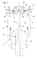
- the strut 2 according to the invention shown in Fig. 1 is a so-called air spring strut, consisting of an air spring 4 and a coaxially arranged shock absorber. 6
- the air spring 4 has two spaced variable end members 8, 10, namely an air spring cover 8 and a rolling piston 10, which are both pressure-tight and tensile strength connected by an air spring bellows 12 and together so enclose an air spring pressure chamber 14.
- On the longitudinal axis 16 of the air spring 4 is the shock absorber 6, which is an integral part of the air spring strut 2.
- the shock absorber 6 has a damper rod 18 and a damper tube 20.
- Damper rod 18 and a damper piston, not shown, as well as the cylindrical inner wall of the damper tube 20 are rotationally symmetrical, so that the damper rod 18 relative to the damper tube 20 not only axial but also can perform rotational movements.
- the "upper" end of the damper rod 18 is non-rotatably embedded in a serving as a damper bearing rubber block 22, which is located in a rigidly attached to the body 24 housing 26.
- the damper tube 20 is rigidly connected to an associated wheel axle (not shown).
- Fig. 1 shows the basic structure of such storage, in the present Embodiment of a ball bearing 28 and an annular seal 30 consists.
- Fig. 2 also shows an annular seal 30 and instead of a ball bearing a sliding ring 32 which is between an outer 34 and a inner bearing shell 36 is embedded.
- FIG. 3 further modification also shows an annular seal 30 and a sliding ring 32 as a pivot bearing. While the sealing ring 30 shown in FIG. 2 is disposed directly between damper rod housing 26 on the one hand and air spring cover 8 on the other hand, according to FIG. 3, the sealing ring 30 together with the sliding ring 32 is embedded in a common two-part bearing shell 34 ', 36'.
Landscapes
- Engineering & Computer Science (AREA)
- General Engineering & Computer Science (AREA)
- Mechanical Engineering (AREA)
- Vehicle Body Suspensions (AREA)
- Fluid-Damping Devices (AREA)
- Coloring Foods And Improving Nutritive Qualities (AREA)
Abstract
Description
Das Federbein stützt sich mit einem Kugellager an der Karosserie ab. Dabei werden alle im Federbein erzeugten Kräfte (Auslenkungsamplituden-abhängige Federkräfte und Auslenkungsgeschwindigkeits-abhängige Dämpferkräfte) durch das Lager geleitet. Damit wird das Lager sowohl auf Druck als auch auf Zug belastet und muss hohe Kraftspitzen aufnehmen.
Um die Lagerbelastungen in "erträglichen" Grenzen zu halten, wird häufig nicht das komplette Federbein sondern lediglich die Feder mit einem Drehlager abgestützt. Die Drehbewegung zwischen Dämpferrohr und -Stange wird in diesem Fall von der Dichtung des Dämpfers aufgenommen. D. h.: die Dämpferstange wird direkt an der Karosserie befestigt.
Die Aufnahme der Drehbewegung durch den Dämpfer wird durch eine rotationssymmetrische Ausbildung von Dämpferkolben und Dämpferrohr (Dämpferzylinder) ermöglicht.
Dadurch reduzieren sich die auf das Drehlager wirkenden Kraftspitzen. Das Drehlager kann kleiner, leichter und kostengünstiger realisiert werden.
Da auf das Drehlager keine Zugkräfte wirken, ergibt sich eine vereinfachte Montage und eine vereinfachte Befestigung.
Bevorzugte Ausgestaltungen und Abwandlungen ergeben sich aus den Unteransprüchen.
Kunststoff-Gleitlager sind erheblich kostengünstiger sowie leichter und kompakter.
Durch eine Anordnung der Dichtung oberhalb des Drehlagers befindet es sich innerhalb des Druckraums der Luftfeder, wo es vor Verschmutzung geschützt ist und somit eine hohe Lebensdauer erwartet werden kann.
Die Luftfeder 4 weist zwei abstandsvariable zueinander angeordnete Endglieder 8, 10, nämlich einen Luftfederdeckel 8 und einen Abrollkolben 10, auf, die beide mittels eines Luftfederbalgs 12 druckdicht und zugfest miteinander verbunden sind und so gemeinsam einen Luftfeder-Druckraum 14 umschließen. Auf der Längsachse 16 der Luftfeder 4 befindet sich der Stoßdämpfer 6, der integraler Bestandteil des Luftfederbeins 2 ist. Der Stoßdämpfer 6 weist eine Dämpferstange 18 und ein Dämpferrohr 20 auf.
Das "obere" Ende der Dämpferstange 18 ist undrehbar in einem als Dämpferlager dienenden Gummiblock 22 eingebettet, der sich in einem starr an der Karosserie 24 angebrachten Gehäuse 26 befindet.
Das Dämpferrohr 20 ist starr mit einer zugeordneten Radachse (nicht dargestellt) verbunden.
Während der in der Fig. 2 dargestellte Dichtring 30 unmittelbar zwischen Dämpferstangen-Gehäuse 26 einerseits und Luftfederdeckel 8 andererseits angeordnet ist, ist gemäß Fig. 3 der Dichtring 30 samt dem Gleitring 32 in eine gemeinsame zweiteilige Lagerschale 34', 36' eingebettet.
- 2
- Federbein, Luftfederbein
- 4
- Luftfeder
- 6
- Stoßdämpfer
- 8, 10
- Endglieder der Luftfeder
- 8
- Luftfederdeckel
- 10
- Abrollkolben, Luftfederkolben
- 12
- Luftfederbalg
- 14
- Luftfederdruckraum
- 16
- Längsachse des (Luft-)Federbeins
- 18
- Dämpferstange
- 20
- Dämpferrohr
- 22
- Gummiblock, Dämpferlager, nichtdrehbares Bauteil
- 24
- Karosserie
- 26
- Gehäuse (des Dämpferstangenkopfes),
Dämpferstangen-Gehäuse - 28
- Kugellager, Drehlager
- 30
- (ringförmige) Dichtung, Dichtring
- 32
- Gleitring
- 34, 34'
- äußere Lagerschale
- 36, 36'
- innere Lagerschale
Claims (5)
- Radführendes Vorderachs-Federbein (2),
bestehend aus einer Feder mit axial darin integriertem Stoßdämpfer (6),
wobei die Feder aus zwei abstandsvariabel zueinander angeordneten Endgliedern (8, 10) mit dazwischen befindlichem Federelement aufgebaut ist, und
wobei der Dämpfer (6) aus einem Dämpferrohr (20) und einer axial darin verschiebbaren und drehbaren Dämpferstange (18) besteht, die über ein nichtdrehbares Dämpferlager (22) an der Karosserie (24) angelenkt ist, und
wobei das "obere" Feder-Endglied (8) mittels eines Drehlagers (28) um seine Längsachse (16) drehbar an der Karosserie (24) angelenkt ist und das "untere" Feder-Endglied (10) fest mit dem Dämpferrohr (20) und so gemeinsam mit einer Vorderachse verbunden ist,
dadurch gekennzeichnet, dass das "obere" Federendglied ein Luftfederdeckel (8) und dass "untere" Federendglied ein Luftfederkolben (10) ist, zwischen denen ein Luftfederbalg (12) druckdicht und zugfest angeordnet ist,
wobei zwischen Luftfederdeckel (8) und dem nichtdrehbaren Bauteil (Dämpferlager, 22) ein Drehlager (28) und eine Dichtung (30) angeordnet ist, die entsprechend einem Radeinschlag auf Drehung belastbar sind. - Federbein nach Anspruch 1,
dadurch gekennzeichnet, dass die Dichtung (30) als Rundschnurring oder als Wellendichtung ausgeführt ist. - Federbein nach Anspruch 1,
dadurch gekennzeichnet, dass das Drehlager (28) als Kunststoff-Gleitlager realisiert ist. - Federbein nach einem der Ansprüche 1 bis 3,
gekennzeichnet durch
Anordnung der Dichtung (30) oberhalb des Drehlagers (28), wobei sich das Lager (28) im Druckraum der Luftfeder (4) befindet. - Federbein nach einem der Ansprüche 1 bis 4,
gekennzeichnet durch
Integration der Dichtung (30) in ein Kunststoff-Gleitlager.
Applications Claiming Priority (2)
| Application Number | Priority Date | Filing Date | Title |
|---|---|---|---|
| DE10320501 | 2003-05-08 | ||
| DE10320501A DE10320501A1 (de) | 2003-05-08 | 2003-05-08 | Radführendes Vorderachs-Federbein |
Publications (2)
| Publication Number | Publication Date |
|---|---|
| EP1475255A1 true EP1475255A1 (de) | 2004-11-10 |
| EP1475255B1 EP1475255B1 (de) | 2008-03-05 |
Family
ID=32981275
Family Applications (1)
| Application Number | Title | Priority Date | Filing Date |
|---|---|---|---|
| EP04006636A Expired - Lifetime EP1475255B1 (de) | 2003-05-08 | 2004-03-19 | Radführendes Vorderachs-Federbein |
Country Status (4)
| Country | Link |
|---|---|
| US (1) | US7011301B2 (de) |
| EP (1) | EP1475255B1 (de) |
| AT (1) | ATE388033T1 (de) |
| DE (2) | DE10320501A1 (de) |
Cited By (3)
| Publication number | Priority date | Publication date | Assignee | Title |
|---|---|---|---|---|
| WO2013029725A3 (de) * | 2011-09-01 | 2013-04-25 | Audi Ag | Luftfedervorrichtung für ein kraftfahrzeug |
| WO2017102584A1 (de) * | 2015-12-18 | 2017-06-22 | Thyssenkrupp Bilstein Gmbh | Luftfederanschlussvorrichtungsabdichtung |
| CN113819177A (zh) * | 2021-08-26 | 2021-12-21 | 隆昌山川机械有限责任公司 | 一种空气弹簧的密封结构 |
Families Citing this family (16)
| Publication number | Priority date | Publication date | Assignee | Title |
|---|---|---|---|---|
| US7284644B2 (en) * | 2005-03-16 | 2007-10-23 | Bfs Diversified Products, Llc | Multiple load path air spring assembly |
| US7175165B1 (en) * | 2005-05-10 | 2007-02-13 | Link Mfg., Ltd. | Air spring and shock absorber assembly for use in suspension systems |
| DE102006037034B4 (de) * | 2006-08-08 | 2009-01-02 | Saf-Holland Gmbh | Luftfeder für ein Fahrzeug |
| DE102007046219A1 (de) * | 2007-09-27 | 2009-04-02 | GM Global Technology Operations, Inc., Detroit | Stützlager für ein Fahrzeug |
| DE102010017336A1 (de) | 2010-06-11 | 2011-12-15 | Contitech Luftfedersysteme Gmbh | Luftfeder-Dämpfer-Modul für Nutzfahrzeuge |
| US8193845B2 (en) * | 2010-07-06 | 2012-06-05 | Microchip Technology Incorporated | Binary-weighted delta-sigma fractional-N frequency synthesizer with digital-to-analog differentiators canceling quantization noise |
| DE102010037096A1 (de) * | 2010-08-20 | 2012-02-23 | Continental Teves Ag & Co. Ohg | Luftfederbein mit elastischer Kolbenlagerung |
| DE102011084665A1 (de) | 2011-10-18 | 2013-04-18 | Continental Teves Ag & Co. Ohg | Elastische Luftfederkolbenlagerung |
| DE102016205741A1 (de) * | 2016-04-05 | 2017-10-05 | Continental Teves Ag & Co. Ohg | Luftfederdeckel |
| US10618366B2 (en) * | 2016-07-08 | 2020-04-14 | Continental Automotive Systems, Inc. | Vehicle air strut with twist lock closure cover |
| US10442266B2 (en) * | 2016-12-05 | 2019-10-15 | Continental Automotive Systems, Inc. | Air spring standing piston bearing |
| WO2019068790A1 (de) * | 2017-10-04 | 2019-04-11 | Continental Teves Ag & Co. Ohg | Luftfederbein mit einem kunststoff-luftfederdeckel |
| CN111433486B (zh) * | 2017-12-01 | 2022-05-10 | 大陆-特韦斯贸易合伙股份公司及两合公司 | 盖中具有加强芯的空气弹簧滑柱组件 |
| DE102019210972A1 (de) * | 2019-07-24 | 2021-01-28 | Ford Global Technologies, Llc | Integrierte Luftfeder- und Stoßdämpfervorrichtung mit stufenloser Einstellbarkeit |
| DE102020203171A1 (de) | 2020-02-05 | 2021-08-05 | Continental Teves Ag & Co. Ohg | Luftfederbein mit einem Schutzbalg zur Übertragung eines Drehmoments |
| CN112727993A (zh) * | 2020-12-24 | 2021-04-30 | 上海保隆汽车科技(安徽)有限公司 | 一种带密封皮膜的空气弹簧减震器 |
Citations (3)
| Publication number | Priority date | Publication date | Assignee | Title |
|---|---|---|---|---|
| US4482135A (en) * | 1981-07-30 | 1984-11-13 | Nissan Motor Company, Limited | MacPherson strut front suspension |
| DE3624296A1 (de) * | 1985-07-26 | 1987-02-12 | Gold Henning | Vorrichtung zum ausgleich der radaufstands-querkraefte an einem federbein |
| US4655438A (en) * | 1985-12-23 | 1987-04-07 | General Motors Corporation | Hydraulically damped dual sleeve air spring suspension |
Family Cites Families (9)
| Publication number | Priority date | Publication date | Assignee | Title |
|---|---|---|---|---|
| JPH0522663Y2 (de) * | 1985-06-11 | 1993-06-10 | ||
| US5009401A (en) * | 1986-07-14 | 1991-04-23 | Bridgestone/Firestone, Inc. | Air spring suspension system with dual path isolation |
| JPH0231907A (ja) * | 1988-07-21 | 1990-02-01 | Tokico Ltd | エアサスペンション |
| DE19505026C2 (de) * | 1995-02-15 | 1996-12-12 | Fichtel & Sachs Ag | Selbstpumpende Luftfeder |
| DE19607804C1 (de) * | 1996-03-01 | 1997-05-07 | Contitech Luftfedersyst Gmbh | Luftfeder zur federnden Abstützung von Fahrzeugbauteilen |
| US5690319A (en) * | 1996-04-15 | 1997-11-25 | General Motors Corporation | Pneumatic suspension system |
| US6227527B1 (en) | 1996-12-17 | 2001-05-08 | Phoenix Aktiengesellschaft | Pneumatic suspension system |
| DE10038267B4 (de) * | 2000-08-04 | 2009-01-02 | Audi Ag | Vorrichtung zur karosserieseitigen Lagerung eines Federbeines |
| DE10221894B4 (de) * | 2002-05-16 | 2005-12-22 | Trelleborg Automotive Technical Centre Gmbh | Luftfedermodul |
-
2003
- 2003-05-08 DE DE10320501A patent/DE10320501A1/de not_active Withdrawn
-
2004
- 2004-03-19 DE DE502004006375T patent/DE502004006375D1/de not_active Expired - Lifetime
- 2004-03-19 AT AT04006636T patent/ATE388033T1/de not_active IP Right Cessation
- 2004-03-19 EP EP04006636A patent/EP1475255B1/de not_active Expired - Lifetime
- 2004-05-10 US US10/841,436 patent/US7011301B2/en not_active Expired - Lifetime
Patent Citations (3)
| Publication number | Priority date | Publication date | Assignee | Title |
|---|---|---|---|---|
| US4482135A (en) * | 1981-07-30 | 1984-11-13 | Nissan Motor Company, Limited | MacPherson strut front suspension |
| DE3624296A1 (de) * | 1985-07-26 | 1987-02-12 | Gold Henning | Vorrichtung zum ausgleich der radaufstands-querkraefte an einem federbein |
| US4655438A (en) * | 1985-12-23 | 1987-04-07 | General Motors Corporation | Hydraulically damped dual sleeve air spring suspension |
Cited By (5)
| Publication number | Priority date | Publication date | Assignee | Title |
|---|---|---|---|---|
| WO2013029725A3 (de) * | 2011-09-01 | 2013-04-25 | Audi Ag | Luftfedervorrichtung für ein kraftfahrzeug |
| US9193239B2 (en) | 2011-09-01 | 2015-11-24 | Audi Ag | Pneumatic spring device for a motor vehicle |
| WO2017102584A1 (de) * | 2015-12-18 | 2017-06-22 | Thyssenkrupp Bilstein Gmbh | Luftfederanschlussvorrichtungsabdichtung |
| US10696116B2 (en) | 2015-12-18 | 2020-06-30 | Thyssenkrupp Bilstein Gmbh | Air spring connecting device seal |
| CN113819177A (zh) * | 2021-08-26 | 2021-12-21 | 隆昌山川机械有限责任公司 | 一种空气弹簧的密封结构 |
Also Published As
| Publication number | Publication date |
|---|---|
| DE10320501A1 (de) | 2004-11-25 |
| DE502004006375D1 (de) | 2008-04-17 |
| US7011301B2 (en) | 2006-03-14 |
| ATE388033T1 (de) | 2008-03-15 |
| EP1475255B1 (de) | 2008-03-05 |
| US20040222576A1 (en) | 2004-11-11 |
Similar Documents
| Publication | Publication Date | Title |
|---|---|---|
| EP1475255B1 (de) | Radführendes Vorderachs-Federbein | |
| EP0160276B1 (de) | Pneumatische Feder-Dämpfer-Einheit | |
| DE102012207792B4 (de) | Radmassen-dämpferbaugruppe | |
| EP0229902B1 (de) | Pneumatische Feder-Dämpfer-Einheit | |
| EP1985475B1 (de) | Aufbauseitige Federbeinlagerung für Radaufhängungen | |
| EP3510303B1 (de) | Luftfedereinheit mit geteilter aussenführung | |
| DE1505522B1 (de) | Hydropneumatischer Einrohr-Teleskopstossdaempfer mit davon unabhaengiger,parallel geschalteter Gasfeder und selbsttaetig steuerbarem Daempfungsgrad,insbesondere fuer Kraftfahrzeuge | |
| DE102008013913A1 (de) | Radaufhängung für gelenkte Räder von Kraftfahrzeugen | |
| WO2005092646A1 (de) | Gasfedersystem mit zentral geführtem schlauchrollbalg | |
| DE3641623C2 (de) | ||
| DE102004002432B4 (de) | Karosserieseitige Lagerung eines Federbeins einer Radaufhängung für Fahrzeuge | |
| EP1929172B1 (de) | Gasfederanordnung | |
| DE102018204485A1 (de) | Luftfederbein mit abgedichtetem Verschlussdeckel | |
| DE102006008608A1 (de) | Radaufhängung | |
| WO2012022509A1 (de) | Luftfederbein mit elastischer kolbenlagerung | |
| DE102016216911A1 (de) | Luftfedereinheit mit großvolumigem Luftfederdeckel | |
| DE102019210972A1 (de) | Integrierte Luftfeder- und Stoßdämpfervorrichtung mit stufenloser Einstellbarkeit | |
| DE2820585C2 (de) | Unabhängige Aufhängung der lenkbaren Vorderräder von Kraftfahrzeugen | |
| DE102018210853A1 (de) | Luftfederbein mit einer torsionsfähigen Drehdichtung | |
| DE4331585C2 (de) | Oberes Stützlager für einen Federdämpfer oder ein Federbein | |
| WO2015028510A1 (de) | Federungsanordnung und fahrrad mit einer solchen | |
| DE3725404C2 (de) | ||
| DE3445461C1 (de) | Winkelbewegliches Führungslager, insbesondere für McPherson-Federbeine von Kraftfahrzeugen | |
| DE4108801A1 (de) | Hydropneumatisches feder-daempfungs-element fuer fahrzeuge insbesondere schienenfahrzeuge | |
| DE2100019A1 (de) | Unabhängige Radaufhängung für Kraftfahrzeuge |
Legal Events
| Date | Code | Title | Description |
|---|---|---|---|
| PUAI | Public reference made under article 153(3) epc to a published international application that has entered the european phase |
Free format text: ORIGINAL CODE: 0009012 |
|
| AK | Designated contracting states |
Kind code of ref document: A1 Designated state(s): AT BE BG CH CY CZ DE DK EE ES FI FR GB GR HU IE IT LI LU MC NL PL PT RO SE SI SK TR |
|
| AX | Request for extension of the european patent |
Extension state: AL LT LV MK |
|
| 17P | Request for examination filed |
Effective date: 20050510 |
|
| AKX | Designation fees paid |
Designated state(s): AT BE BG CH CY CZ DE DK EE ES FI FR GB GR HU IE IT LI LU MC NL PL PT RO SE SI SK TR |
|
| GRAP | Despatch of communication of intention to grant a patent |
Free format text: ORIGINAL CODE: EPIDOSNIGR1 |
|
| GRAS | Grant fee paid |
Free format text: ORIGINAL CODE: EPIDOSNIGR3 |
|
| GRAA | (expected) grant |
Free format text: ORIGINAL CODE: 0009210 |
|
| AK | Designated contracting states |
Kind code of ref document: B1 Designated state(s): AT BE BG CH CY CZ DE DK EE ES FI FR GB GR HU IE IT LI LU MC NL PL PT RO SE SI SK TR |
|
| REG | Reference to a national code |
Ref country code: GB Ref legal event code: FG4D Free format text: NOT ENGLISH |
|
| REG | Reference to a national code |
Ref country code: CH Ref legal event code: EP |
|
| REG | Reference to a national code |
Ref country code: IE Ref legal event code: FG4D Free format text: LANGUAGE OF EP DOCUMENT: GERMAN |
|
| REF | Corresponds to: |
Ref document number: 502004006375 Country of ref document: DE Date of ref document: 20080417 Kind code of ref document: P |
|
| PG25 | Lapsed in a contracting state [announced via postgrant information from national office to epo] |
Ref country code: FI Free format text: LAPSE BECAUSE OF FAILURE TO SUBMIT A TRANSLATION OF THE DESCRIPTION OR TO PAY THE FEE WITHIN THE PRESCRIBED TIME-LIMIT Effective date: 20080305 Ref country code: ES Free format text: LAPSE BECAUSE OF FAILURE TO SUBMIT A TRANSLATION OF THE DESCRIPTION OR TO PAY THE FEE WITHIN THE PRESCRIBED TIME-LIMIT Effective date: 20080616 |
|
| NLV1 | Nl: lapsed or annulled due to failure to fulfill the requirements of art. 29p and 29m of the patents act | ||
| BERE | Be: lapsed |
Owner name: CONTINENTAL A.G. Effective date: 20080331 |
|
| PG25 | Lapsed in a contracting state [announced via postgrant information from national office to epo] |
Ref country code: SI Free format text: LAPSE BECAUSE OF FAILURE TO SUBMIT A TRANSLATION OF THE DESCRIPTION OR TO PAY THE FEE WITHIN THE PRESCRIBED TIME-LIMIT Effective date: 20080305 Ref country code: PL Free format text: LAPSE BECAUSE OF FAILURE TO SUBMIT A TRANSLATION OF THE DESCRIPTION OR TO PAY THE FEE WITHIN THE PRESCRIBED TIME-LIMIT Effective date: 20080305 |
|
| REG | Reference to a national code |
Ref country code: IE Ref legal event code: FD4D |
|
| PG25 | Lapsed in a contracting state [announced via postgrant information from national office to epo] |
Ref country code: SK Free format text: LAPSE BECAUSE OF FAILURE TO SUBMIT A TRANSLATION OF THE DESCRIPTION OR TO PAY THE FEE WITHIN THE PRESCRIBED TIME-LIMIT Effective date: 20080305 Ref country code: CZ Free format text: LAPSE BECAUSE OF FAILURE TO SUBMIT A TRANSLATION OF THE DESCRIPTION OR TO PAY THE FEE WITHIN THE PRESCRIBED TIME-LIMIT Effective date: 20080305 Ref country code: MC Free format text: LAPSE BECAUSE OF NON-PAYMENT OF DUE FEES Effective date: 20080331 Ref country code: SE Free format text: LAPSE BECAUSE OF FAILURE TO SUBMIT A TRANSLATION OF THE DESCRIPTION OR TO PAY THE FEE WITHIN THE PRESCRIBED TIME-LIMIT Effective date: 20080605 Ref country code: NL Free format text: LAPSE BECAUSE OF FAILURE TO SUBMIT A TRANSLATION OF THE DESCRIPTION OR TO PAY THE FEE WITHIN THE PRESCRIBED TIME-LIMIT Effective date: 20080305 Ref country code: PT Free format text: LAPSE BECAUSE OF FAILURE TO SUBMIT A TRANSLATION OF THE DESCRIPTION OR TO PAY THE FEE WITHIN THE PRESCRIBED TIME-LIMIT Effective date: 20080805 |
|
| REG | Reference to a national code |
Ref country code: CH Ref legal event code: PL |
|
| ET | Fr: translation filed | ||
| PG25 | Lapsed in a contracting state [announced via postgrant information from national office to epo] |
Ref country code: RO Free format text: LAPSE BECAUSE OF FAILURE TO SUBMIT A TRANSLATION OF THE DESCRIPTION OR TO PAY THE FEE WITHIN THE PRESCRIBED TIME-LIMIT Effective date: 20080305 |
|
| PLBE | No opposition filed within time limit |
Free format text: ORIGINAL CODE: 0009261 |
|
| STAA | Information on the status of an ep patent application or granted ep patent |
Free format text: STATUS: NO OPPOSITION FILED WITHIN TIME LIMIT |
|
| PG25 | Lapsed in a contracting state [announced via postgrant information from national office to epo] |
Ref country code: IE Free format text: LAPSE BECAUSE OF FAILURE TO SUBMIT A TRANSLATION OF THE DESCRIPTION OR TO PAY THE FEE WITHIN THE PRESCRIBED TIME-LIMIT Effective date: 20080305 Ref country code: DK Free format text: LAPSE BECAUSE OF FAILURE TO SUBMIT A TRANSLATION OF THE DESCRIPTION OR TO PAY THE FEE WITHIN THE PRESCRIBED TIME-LIMIT Effective date: 20080305 Ref country code: LI Free format text: LAPSE BECAUSE OF NON-PAYMENT OF DUE FEES Effective date: 20080331 Ref country code: EE Free format text: LAPSE BECAUSE OF FAILURE TO SUBMIT A TRANSLATION OF THE DESCRIPTION OR TO PAY THE FEE WITHIN THE PRESCRIBED TIME-LIMIT Effective date: 20080305 Ref country code: CH Free format text: LAPSE BECAUSE OF NON-PAYMENT OF DUE FEES Effective date: 20080331 |
|
| 26N | No opposition filed |
Effective date: 20081208 |
|
| GBPC | Gb: european patent ceased through non-payment of renewal fee |
Effective date: 20080605 |
|
| PG25 | Lapsed in a contracting state [announced via postgrant information from national office to epo] |
Ref country code: BE Free format text: LAPSE BECAUSE OF NON-PAYMENT OF DUE FEES Effective date: 20080331 |
|
| REG | Reference to a national code |
Ref country code: FR Ref legal event code: ST Effective date: 20090119 |
|
| PG25 | Lapsed in a contracting state [announced via postgrant information from national office to epo] |
Ref country code: BG Free format text: LAPSE BECAUSE OF FAILURE TO SUBMIT A TRANSLATION OF THE DESCRIPTION OR TO PAY THE FEE WITHIN THE PRESCRIBED TIME-LIMIT Effective date: 20080605 Ref country code: FR Free format text: LAPSE BECAUSE OF NON-PAYMENT OF DUE FEES Effective date: 20080331 |
|
| REG | Reference to a national code |
Ref country code: GB Ref legal event code: S28 Free format text: APPLICATION FILED |
|
| PG25 | Lapsed in a contracting state [announced via postgrant information from national office to epo] |
Ref country code: GB Free format text: LAPSE BECAUSE OF NON-PAYMENT OF DUE FEES Effective date: 20080605 |
|
| PG25 | Lapsed in a contracting state [announced via postgrant information from national office to epo] |
Ref country code: AT Free format text: LAPSE BECAUSE OF NON-PAYMENT OF DUE FEES Effective date: 20080319 Ref country code: IT Free format text: LAPSE BECAUSE OF NON-PAYMENT OF DUE FEES Effective date: 20080319 |
|
| PG25 | Lapsed in a contracting state [announced via postgrant information from national office to epo] |
Ref country code: CY Free format text: LAPSE BECAUSE OF FAILURE TO SUBMIT A TRANSLATION OF THE DESCRIPTION OR TO PAY THE FEE WITHIN THE PRESCRIBED TIME-LIMIT Effective date: 20080305 |
|
| REG | Reference to a national code |
Ref country code: GB Ref legal event code: S28 Free format text: RESTORATION ALLOWED Effective date: 20091012 |
|
| PG25 | Lapsed in a contracting state [announced via postgrant information from national office to epo] |
Ref country code: LU Free format text: LAPSE BECAUSE OF NON-PAYMENT OF DUE FEES Effective date: 20080319 Ref country code: HU Free format text: LAPSE BECAUSE OF FAILURE TO SUBMIT A TRANSLATION OF THE DESCRIPTION OR TO PAY THE FEE WITHIN THE PRESCRIBED TIME-LIMIT Effective date: 20080906 |
|
| PG25 | Lapsed in a contracting state [announced via postgrant information from national office to epo] |
Ref country code: TR Free format text: LAPSE BECAUSE OF FAILURE TO SUBMIT A TRANSLATION OF THE DESCRIPTION OR TO PAY THE FEE WITHIN THE PRESCRIBED TIME-LIMIT Effective date: 20080305 |
|
| PG25 | Lapsed in a contracting state [announced via postgrant information from national office to epo] |
Ref country code: GR Free format text: LAPSE BECAUSE OF FAILURE TO SUBMIT A TRANSLATION OF THE DESCRIPTION OR TO PAY THE FEE WITHIN THE PRESCRIBED TIME-LIMIT Effective date: 20080606 |
|
| REG | Reference to a national code |
Ref country code: DE Ref legal event code: R081 Ref document number: 502004006375 Country of ref document: DE Owner name: CONTINENTAL TEVES AG & CO. OHG, DE Free format text: FORMER OWNER: CONTINENTAL AKTIENGESELLSCHAFT, 30165 HANNOVER, DE Effective date: 20110414 |
|
| PGFP | Annual fee paid to national office [announced via postgrant information from national office to epo] |
Ref country code: GB Payment date: 20130326 Year of fee payment: 10 |
|
| GBPC | Gb: european patent ceased through non-payment of renewal fee |
Effective date: 20140319 |
|
| PG25 | Lapsed in a contracting state [announced via postgrant information from national office to epo] |
Ref country code: GB Free format text: LAPSE BECAUSE OF NON-PAYMENT OF DUE FEES Effective date: 20140319 |
|
| PGFP | Annual fee paid to national office [announced via postgrant information from national office to epo] |
Ref country code: DE Payment date: 20180331 Year of fee payment: 15 |
|
| REG | Reference to a national code |
Ref country code: DE Ref legal event code: R119 Ref document number: 502004006375 Country of ref document: DE |
|
| PG25 | Lapsed in a contracting state [announced via postgrant information from national office to epo] |
Ref country code: DE Free format text: LAPSE BECAUSE OF NON-PAYMENT OF DUE FEES Effective date: 20191001 |