EP1473554B1 - Kochgeschirr und Verfahren und Vorrichtung zur Regelung der Heizmitteln einer Kochapparat - Google Patents
Kochgeschirr und Verfahren und Vorrichtung zur Regelung der Heizmitteln einer Kochapparat Download PDFInfo
- Publication number
- EP1473554B1 EP1473554B1 EP04291065A EP04291065A EP1473554B1 EP 1473554 B1 EP1473554 B1 EP 1473554B1 EP 04291065 A EP04291065 A EP 04291065A EP 04291065 A EP04291065 A EP 04291065A EP 1473554 B1 EP1473554 B1 EP 1473554B1
- Authority
- EP
- European Patent Office
- Prior art keywords
- temperature
- receptacle
- container
- content
- heating means
- Prior art date
- Legal status (The legal status is an assumption and is not a legal conclusion. Google has not performed a legal analysis and makes no representation as to the accuracy of the status listed.)
- Expired - Lifetime
Links
Images
Classifications
-
- G—PHYSICS
- G01—MEASURING; TESTING
- G01K—MEASURING TEMPERATURE; MEASURING QUANTITY OF HEAT; THERMALLY-SENSITIVE ELEMENTS NOT OTHERWISE PROVIDED FOR
- G01K1/00—Details of thermometers not specially adapted for particular types of thermometer
- G01K1/02—Means for indicating or recording specially adapted for thermometers
- G01K1/026—Means for indicating or recording specially adapted for thermometers arrangements for monitoring a plurality of temperatures, e.g. by multiplexing
-
- A—HUMAN NECESSITIES
- A47—FURNITURE; DOMESTIC ARTICLES OR APPLIANCES; COFFEE MILLS; SPICE MILLS; SUCTION CLEANERS IN GENERAL
- A47J—KITCHEN EQUIPMENT; COFFEE MILLS; SPICE MILLS; APPARATUS FOR MAKING BEVERAGES
- A47J36/00—Parts, details or accessories of cooking-vessels
- A47J36/32—Time-controlled igniting mechanisms or alarm devices
- A47J36/321—Time-controlled igniting mechanisms or alarm devices the electronic control being performed over a network, e.g. by means of a handheld device
-
- A—HUMAN NECESSITIES
- A47—FURNITURE; DOMESTIC ARTICLES OR APPLIANCES; COFFEE MILLS; SPICE MILLS; SUCTION CLEANERS IN GENERAL
- A47J—KITCHEN EQUIPMENT; COFFEE MILLS; SPICE MILLS; APPARATUS FOR MAKING BEVERAGES
- A47J43/00—Implements for preparing or holding food, not provided for in other groups of this subclass
- A47J43/28—Other culinary hand implements, e.g. spatulas, pincers, forks or like food holders, ladles, skimming ladles, cooking spoons; Spoon-holders attached to cooking pots
Definitions
- the present invention relates to a kitchen utensil intended to be introduced into a cooking vessel and comprising means for measuring temperature.
- It also relates to a method and a device for controlling the heating means of a cooking appliance adapted to cooperate with a kitchen utensil according to the present invention.
- the present invention relates generally to the field of domestic cooking appliances, and more particularly the electric or gas hobs having electronic control means of the heating elements.
- thermopile which deduces the temperature of the container or its contents by virtue of the infrared radiation emitted by the latter.
- a measured temperature value is transmitted to means for regulating the heating elements of a hob to allow servo-control of the power delivered by these heating elements as a function of the comparison of this measured temperature and a set value chosen by a user.
- the present invention aims to improve the systems described above by implementing a kitchen utensil provided with temperature measuring means to obtain a perfect control of the temperature of the container and its contents.
- a kitchen utensil intended to be introduced into a cooking vessel, having temperature measuring means and means for transmitting a temperature measurement to a means of control of the means. heating a cooking appliance.
- the temperature measuring means comprise at least two temperature sensors, a first temperature sensor being disposed at one end of the kitchen utensil adapted to come into contact with the bottom of the container and a second temperature sensor being arranged at a distance. from this end.
- the cooking utensil according to the present invention makes it possible to measure both the temperature of the bottom of the container and the temperature of its contents. It is thus possible to use these two values in the regulation of the heating means of the container.
- the regulation implemented to control the heating means uses not only a temperature measurement comparable to a set value, as is conventionally described in the state of the art, but also the difference existing between the bottom temperature. of the container and the temperature of its contents.
- This regulation makes it possible to obtain perfect control of the heating of the container and in particular a cooking without burning or attaching the contents to the bottom of the container.
- the heating means are controlled from the regulation of the value of the bottom temperature of the container to the acquired reference value and the extinction of the heating means is controlled when the difference between the bottom temperature of the container and the temperature of the contents of the container is negative.
- the regulation as a function of the set temperature is carried out from the value measured at the bottom of the container, the heating means being cut off when the temperature of the contents exceeds the temperature of the bottom of the container.
- This provides a regulation to obtain a perfect control of both the bottom temperature of the container and its contents, to a predetermined set value.
- a step of issuing a warning signal is set implemented.
- a warning signal makes it possible to alert the user who will have to mix the contents of the container in order to homogenise his temperature thus avoiding any attachment. or burning the contents on the bottom of the container.
- control method further comprises a temperature rise phase of the bottom of the container to the acquired target value, this temperature rise phase comprising a step of reducing the power of the heating means when the difference between the bottom temperature of the container and the temperature of the contents of the container is greater than a second threshold value.
- the control of the heating means is also implemented during the temperature rise phase, allowing a very rapid rise in temperature, at full power of the heating elements, while reducing this power only in case of overheating of the bottom of the container by to its contents, to avoid burning food.
- the temperature rise phase further comprises a step of issuing a warning signal when the difference between the bottom temperature of the container and the temperature of the contents of the container is greater than a third threshold value.
- the warning signal makes it possible to alert the user to the need to mix the contents of the container.
- this warning signal is preferably a sound signal.
- a device for controlling heating means of a cooking appliance adapted to cooperate with a kitchen utensil according to the invention.
- This servo-control device comprises means for receiving temperature measurements, means for acquiring a set temperature and regulating means adapted to control the means of heating according to the set temperature, a temperature measurement of the bottom of a container, a temperature measurement of the contents of a container and the difference between the bottom temperature of the container and the temperature of the contents of the container.
- This servo device has advantages and features identical to those described above for the control method that it implements.
- the present invention aims at an electronically controlled domestic hob means for heating a container comprising a servo device according to the invention.
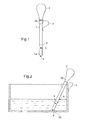
- This kitchen utensil is intended to be immersed in the contents of a container to monitor the temperature when cooking a food in this container.
- This kitchen utensil is in the general form of a rigid rod 1 serving to support the various functional elements described below.
- This rigid rod 1 is preferably made of plastic resistant to temperatures of the order of 150 ° C.
- This rod 1 thus forms a grip handle of the utensil allowing the user to manipulate it, and in particular to introduce it into a container.
- this utensil in operation, is intended to have a first end 1a introduced into the cooking vessel and a second end 1b to be held at the end of the rod 1 outside the container.
- This second end 1b includes means 2 for transmitting a temperature measurement adapted to cooperate with a servo device which will be described later.
- these transmission means 2 of a temperature measurement are wireless transmission means operating in the field of infrared, radiofrequency or microwave.
- These transmission means 2 also preferably include means for processing the temperature measurements, particularly adapted to periodically calculate an average temperature value from a continuous value measured by a sensor.
- processing means are preferably conventional electronic means using a microprocessor.
- a spring ring 3 is slidably mounted by means of a sliding ring 3a on the rod 1.
- this spring ring 3 can thus be adjusted along the rod 1 depending on the height of the container to allow to fix this rod 1 to the edge of the container.
- this kitchen utensil comprises two temperature sensors.
- a first sensor 4 is disposed at the end 1a of the kitchen utensil.
- this end 1a is adapted to come into contact with the bottom of the container.
- This temperature sensor 4 is preferably inserted into a food metal tube in order to improve its response time.
- This temperature sensor 4 thus makes it possible to dynamically and quickly measure the temperature of the bottom of the container.
- a second temperature sensor 5 is disposed at a distance from the end 1a of the rod 1.
- This temperature sensor 5 is overmolded in the rod 1 and makes it possible to measure an average temperature of a content of the cooking vessel.
- this temperature sensor is disposed in a portion of the rod 1 adapted to be immersed in the contents of the container.
- a graduation shown schematically by the reference 6 may be provided on the rod 1 beyond the second temperature sensor 5 to allow the user to visually check the immersion of the second temperature sensor 5 within the container contents.
- These temperature sensors 4, 5 are preferably NTC type (negative temperature coefficient) type of sensors.
- This kitchen utensil thus makes it possible to simultaneously measure the temperature of the bottom T4 of the container and the temperature of its contents T5.
- the transmission means 2 are adapted, after processing the values measured by the sensors 4, 5, to address these temperature values T4, T5 to a servo device described later.
- T4, T5 are preferably transmitted sequentially in a frame of the type: Start T4; T5 stop.
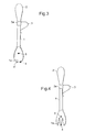
- FIGS. 3 and 4 of the more common forms of kitchen utensil that can be used for the utensil described in FIG.
- this kitchen utensil can consist of a spoon.
- the first temperature sensor 4 is disposed at an end 1a of the spoon adapted to come into contact with the bottom of the container.
- a first tip 4 incorporates a temperature sensor 4 and a second tip 4 'is intended to balance the utensil on the bottom of the container.
- a second temperature sensor 5 is disposed between the end 1a and the handle of the spoon.
- this second temperature sensor 5 is overmolded in the curved portion of the spoon.
- a graduation 6 may be provided on the rod 1, for example at the junction of the handle 1 and the curved portion of the spoon.
- FIG. 4 illustrates a third embodiment of the invention in which the kitchen utensil consists of a fork.
- a first temperature sensor 4 is disposed at one end 1a of a tooth of the fork and a second temperature sensor 5 is disposed between this end 1a and the handle 1 of the fork.
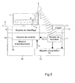
- This servo system generally comprises a cooking utensil as described previously, intended to be introduced into a cooking vessel 7.
- This cooking vessel 7 is adapted to be heated by heating means 8 of a cooking appliance 9.
- the servo system also comprises, cooperating with the kitchen utensil, a servo-control device 10.
- This control device associated with the cooking appliance 9 firstly comprises means 11 for receiving temperature measurements.
- These receiving means 11 cooperate with the transmission means 2 of the kitchen utensil and are thus adapted to receive temperature values representing the temperature of the contents of the container and the temperature of the bottom of the container.
- the receiving means 11 can successively extract the value of the bottom temperature T4, then the content temperature value T5.
- these receiving means may also be wireless reception means, operating in the infrared, radio frequency or microwave.
- reception means 11 and these transmission means 2 may be wired transmission means.
- This control device 10 also comprises means 12 for acquiring a set temperature Tc.
- These acquisition means 12 of a set temperature are adapted to cooperate with a keyboard 13 forming an interface with the user.
- the user can thus conventionally set a set temperature to the cooking appliance, using the keyboard 13. It can alternatively select a cooking function of the type "heat”, “boil”, “fry”. ..
- Each culinary function can be associated with a predetermined set value.
- This setpoint value Tc acquired by the acquisition means 12, and the temperature values received by the reception means 11 are transmitted to control means 14 adapted to control the heating means 8.
- control means 14 and their control algorithm are preferably microprocessor systems adapted to store control programs.
- control means 14 apart from the type of control they implement and which will be described later with reference to the servo-control method according to the present invention, are conventionally used in electronically controlled domestic hobs. heating means.
- the algorithm for regulating and controlling the heating means 8 is a function not only of the set temperature Tc, a temperature measurement T4 of the bottom of a container and a measurement of temperature T5 of the contents of a container, but also of the difference T4 - T5 calculated between the bottom temperature T4 of the container and the temperature of the contents T5 of the container.
- This control device 10 further comprises warning means 15 controlled by the control means 14.
- warning means 15 consist preferentially of means for transmitting a sound signal, thus making it possible to emit an audible alarm, especially when the difference between the temperature of the bottom T4 of the receptacle and the temperature of the contents T5 of the receptacle is greater than a predetermined threshold value.
- This audible alarm thus makes it possible to signal to the user the need to stir the contents in order to homogenize the temperature of the latter and to avoid any attachment of the contents to the bottom of the container.
- This control method is implemented from the background temperature T4, the temperature of the content T5, the difference of these two temperatures T4-T5 and the desired set value Tc.
- a set temperature value Tc of the order of 102 ° C. is assigned by the acquisition means 12.
- a reference value Tc of the order of 80 ° C. is assigned by the acquisition means 12.
- the servo-control method firstly comprises a temperature rise phase and then a regulation phase.
- the power of the heating means is adjusted to increase the temperature of the container and its contents as quickly as possible to the set temperature Tc.
- this temperature rise phase is adapted to raise the temperature of the bottom T4 of the container to the acquired setpoint value Tc.
- the power delivered by the heating means 8 is maximum.
- this threshold value can be set at 10 ° C.
- the power delivered by the heating means 8 is reduced so as not to attach the contents to the bottom of the container.
- the audible signal is intended to alert the user to the need to stir the contents of the container.
- this other threshold value triggering the emission of a warning signal can be set at 20 ° C.
- the heating means are controlled from the regulation of the value of the bottom temperature T4 of the container to the acquired setpoint value Tc.
- This regulation of the value of the bottom temperature T4 around the setpoint value Tc can be carried out in a conventional manner from the value of this temperature T4 and its derivative, according to a regulation mode of the PID type (Proportional Integral Derivative ).
- the bottom temperature T4 of the container is compared with the temperature T5 of its contents in order to control the extinction of the heating means 8 when the difference T4 -T5 is negative, that is to say when the The temperature of the contents of the container becomes higher than the temperature of the bottom of the container, and thereby exceeds the predetermined set point.
- this warning signal is preferably a sound signal to indicate to the user the need to stir the contents to prevent any attachment thereof at the bottom of the container.
- the predetermined threshold value during this regulation step may be of the order of 15 ° C.
- the power delivered by the heating means 8 is maximum as long as the temperature of the bottom T4 of the container is lower than the set value Tc acquired.
- the contents of the container is typically oil that can be mounted up to the temperature of 150 ° C without risk of burning or attachment to the bottom of the container .
- the control method continues with a control phase in which the heating means 8 are controlled from the regulation of the value of the bottom temperature T4. from the container to the acquired setpoint value Tc.
- this regulation can be of the PID type.
- the extinction of the heating means is controlled when the difference between this bottom temperature T4 of the container and the temperature of the content T5 becomes negative, that is to say that the temperature of the contents T5 of the container becomes greater than the temperature of the bottom T4 of the container.
- the servo-control method according to the invention makes it possible, thanks to the use of the values of the background temperatures T4 and of the content T5, possibly of their derivative and especially of their difference, a perfect control of the power delivered by the heating means 8 to obtain the expected cooking result, without risk of overheating the contents of the container 7.
- a warning signal preferably a sound signal
- the issuance of a warning signal to signal to the user the need to stir the contents to homogenize the temperature in the container.
- the cooking utensil according to the invention is particularly well adapted to allow the user to stir the contents as soon as it is in the form of a spoon or fork as illustrated. Figures 3 and 4.
- This control method and the control device 10 adapted to implement this method can be integrated into any type of electronically controlled hob means for heating a container.
- this servo-control device can be integrated with an induction table, for example a touch-sensitive keyboard, a radiant or electronically controlled halogen table, or a gas table whose power can be adjusted by means of a valve modulating the flow of gas, this valve being controlled electronically.
- an induction table for example a touch-sensitive keyboard, a radiant or electronically controlled halogen table, or a gas table whose power can be adjusted by means of a valve modulating the flow of gas, this valve being controlled electronically.
- the warning signal intended to alert the user to the need to stir the contents of the container may be a visual signal, such as for example the display of the term "stir" on a screen integrated in the plane of the table. Cooking.
Landscapes
- Engineering & Computer Science (AREA)
- Food Science & Technology (AREA)
- Physics & Mathematics (AREA)
- General Physics & Mathematics (AREA)
- Mechanical Engineering (AREA)
- Cookers (AREA)
- Electric Stoves And Ranges (AREA)
- Control Of Combustion (AREA)
- Control Of Resistance Heating (AREA)
Claims (15)
- Küchenutensil zum Einführen in ein Kochgefäß (7), mit Mitteln zum Messen der Temperatur (4, 5) und Mitteln zum Übertragen (2) einer Temperaturmessung an eine Einrichtung zum Regeln (10) von Heizmitteln (8) eines Kochgeräts (9), dadurch gekennzeichnet, dass die Temperaturmessungsmittel mindestens zwei Temperatursensoren aufweisen, wobei ein erster Temperatursensor (4) an einem Ende (1a) des Küchenutensils, das dazu vorgesehen ist, mit dem Boden des Behälters (7) in Berührung zu kommen, und ein zweiter Temperatursensor (5) vom Ende (1 a) beabstandet angeordnet ist.
- Küchenutensil nach Anspruch 1, dadurch gekennzeichnet, dass der zweite Temperatursensor (5) dazu vorgesehen ist, eine Durchschnittstemperatur eines Inhalts des Kochbehälters (7) zu messen.
- Küchenutensil nach einem der Ansprüche 1 oder 2, dadurch gekennzeichnet, dass es eine über dem zweiten Temperatursensor (5) angeordnete Strichteilung (6) aufweist.
- Küchenutensil nach einem der Ansprüche 1 bis 3, dadurch gekennzeichnet, dass es aus einem Löffel besteht, wobei ein erster Temperatursensor (4) an einem Ende (1 a) des Löffels, das dazu vorgesehen ist, mit dem Boden des Behälters (7) in Berührung zu kommen, und ein zweiter Temperatursensor (5) zwischen dem Ende (1a) und dem Stiel (1) des Löffels angeordnet ist.
- Küchenutensil nach einem der Ansprüche 1 bis 3, dadurch gekennzeichnet, dass es aus einer Gabel besteht, wobei ein erster Temperatursensor (4) an einem Ende (1 a) eines Zinkens der Gabel und ein zweiter Temperatursensor (5) zwischen dem Ende (1a) und dem Griff (1) der Gabel angeordnet ist.
- Verfahren zum Regeln von Heizmitteln (8) eines Kochgeräts (9), wobei die Heizmittel (8) dazu vorgesehen sind, den Inhalt des Kochbehälters (7) zu heizen, dadurch gekennzeichnet, dass es folgende Schritte aufweist:- Aufnahme einer Messung der Temperatur (T4) des Bodens eines Behälters;- Aufnahme einer Messung der Temperatur (T5) des Inhalts eines Behälters;- Erhalten einer Solltemperatur (Tc); und- Regelung der Heizmittel (8) in Abhängigkeit von der Solltemperatur (Tc), der Messung der Bodentemperatur (T4) eines Behälters, der Messung der Temperatur des Inhalts (T5) eines Behälters und von dem Unterschied (T4-T5) zwischen der Temperatur des Bodens des Behälters und der Temperatur des Inhalts des Behälters (7).
- Regelungsverfahren nach Anspruch 6, dadurch gekennzeichnet, dass beim Schritt der Regelung die Heizmittel (8) in Abhängigkeit von der Regelung des Werts der Bodentemperatur (T4) des Behälters auf den erhaltenen Sollwert (Tc) geregelt werden und dass das Abschalten der Heizmittel (8) gesteuert wird, wenn die Differenz (T4 - T5) zwischen der Bodentemperatur des Behälters und der Temperatur des Inhalts des Behälters negativ ist.
- Regelungsverfahren nach einem der Ansprüche 6 oder 7, dadurch gekennzeichnet, dass beim Schritt der Regelung ein Schritt des Sendens eines Warnsignals ausgeführt wird, wenn der Unterschied (T4 - T5) zwischen der Temperatur des Bodens des Behälters und der Temperatur des Inhalts des Behälters (7) höher als ein vorgegebener Schwellenwert ist.
- Regelungsverfahren nach einem der Ansprüche 6 bis 8, dadurch gekennzeichnet, dass es zudem eine Phase des Anstiegs der Bodentemperatur des Behälters (7) auf den erhaltenen Sollwert (Tc) umfasst, wobei diese Phase des Temperaturanstiegs einen Schritt der Verringerung der Leistung der Heizmittel (8) aufweist, wenn der Unterschied (T4-T5) zwischen der Temperatur des Bodens des Behälters und der Temperatur des Inhalts des Behälters (7) höher als ein zweiter Schwellenwert ist.
- Regelungsverfahren nach Anspruch 9, dadurch gekennzeichnet, dass die Phase des Anstiegs der Temperatur zudem einen Schritt des Sendens eines Warnsignals umfasst, wenn der Unterschied (T4 - T5) zwischen der Temperatur des Bodens des Behälters und der Temperatur des Inhalts des Behälters (7) höher als ein dritter Schwellenwert ist.
- Regelungsverfahren nach Anspruch 10, dadurch gekennzeichnet, dass der dritte Schwellenwert höher ist als der zweite Schwellenwert.
- Regelungsverfahren nach einem der Ansprüche 8 oder 10, dadurch gekennzeichnet, dass das Warnsignal ein Schallsignal ist.
- Vorrichtung zum Regeln von Heizmitteln (8) eines Kochgeräts (9), die dazu vorgesehen ist, mit einem Küchenutensil nach einem der Ansprüche 1 bis 5 zusammenzuwirken, dadurch gekennzeichnet, dass sie Mittel zum Aufnehmen (11) von Temperaturmessungen (T4, T4), Mittel zum Erhalten (12) einer Solltemperatur (Tc) und Regelungsmittel (14) aufweist, die dazu vorgesehen sind, die Heizmittel (8) in Abhängigkeit von der Solltemperatur (Tc), einer Messung der Bodentemperatur (T4) eines Behälters (7), einer Messung der Temperatur des Inhalts (T5) eines Behälters (7) und der Differenz (T4 - T5) zwischen der Bodentemperatur des Behälters und der Temperatur des Inhalts des Behälters zu regeln.
- Regelungsvorrichtung nach Anspruch 13, dadurch gekennzeichnet, dass sie zudem Warnmittel (15) wie Mittel zum Senden eines Schallsignals aufweist, die dazu vorgesehen sind, durch die Regelungsmittel (14) gesteuert zu werden, wenn der Unterschied (T4-T5) zwischen der Temperatur des Bodens des Behälters und der Temperatur des Inhalts des Behälters höher als ein vorgegebener Schwellenwert ist.
- Haushaltskochplatte mit elektronischer Steuerung der Heizmittel (8) eines Behälters (7), dadurch gekennzeichnet, dass sie eine Regelungsvorrichtung (10) nach einem der Ansprüche 13 oder 14 aufweist.
Applications Claiming Priority (2)
| Application Number | Priority Date | Filing Date | Title |
|---|---|---|---|
| FR0305282 | 2003-04-29 | ||
| FR0305282A FR2854459B1 (fr) | 2003-04-29 | 2003-04-29 | Ustensile de cuisine et procede et dispositif d'asservissement de moyens de chauffage d'un appareil de cuisson |
Publications (2)
| Publication Number | Publication Date |
|---|---|
| EP1473554A1 EP1473554A1 (de) | 2004-11-03 |
| EP1473554B1 true EP1473554B1 (de) | 2007-09-19 |
Family
ID=32982332
Family Applications (1)
| Application Number | Title | Priority Date | Filing Date |
|---|---|---|---|
| EP04291065A Expired - Lifetime EP1473554B1 (de) | 2003-04-29 | 2004-04-23 | Kochgeschirr und Verfahren und Vorrichtung zur Regelung der Heizmitteln einer Kochapparat |
Country Status (5)
| Country | Link |
|---|---|
| EP (1) | EP1473554B1 (de) |
| AT (1) | ATE373815T1 (de) |
| DE (1) | DE602004008990T2 (de) |
| ES (1) | ES2294444T3 (de) |
| FR (1) | FR2854459B1 (de) |
Cited By (4)
| Publication number | Priority date | Publication date | Assignee | Title |
|---|---|---|---|---|
| US9220362B2 (en) | 2009-09-08 | 2015-12-29 | Eades Appliance Technology, Llc | Sous-vide cooker |
| USD816396S1 (en) | 2016-02-02 | 2018-05-01 | Eades Appliance Technology, Llc | Cooker lid |
| USD817068S1 (en) | 2016-02-02 | 2018-05-08 | Eades Appliance Technology, Llc | Cooker |
| USD821134S1 (en) | 2016-02-02 | 2018-06-26 | Eades Appliance Technology, Llc | Cooker |
Families Citing this family (7)
| Publication number | Priority date | Publication date | Assignee | Title |
|---|---|---|---|---|
| ES2328769B1 (es) | 2007-01-24 | 2010-08-30 | Pointjust, S.L. | Dispositivo y metodo para el control de la coccion de alimentos. |
| DE102012008612A1 (de) * | 2012-04-27 | 2013-10-31 | Ika-Werke Gmbh & Co. Kg | Temperaturmessvorrichtung |
| EP2659808B1 (de) | 2012-05-04 | 2017-12-13 | Electrolux Home Products Corporation N.V. | Temperaturdetektionsanordnung und zugehöriger Deckel für einen Kochtopf |
| EP2884580B1 (de) | 2013-12-12 | 2019-10-09 | Electrolux Appliances Aktiebolag | Antennenanordnung und Küchenvorrichtung |
| AT517611B1 (de) * | 2015-09-15 | 2017-03-15 | Fluxron Solutions Ag | Kochhilfsvorrichtung |
| AT517723B1 (de) * | 2015-09-15 | 2017-06-15 | Fluxron Solutions Ag | Kochhilfsvorrichtung |
| EP3454701A1 (de) * | 2016-05-09 | 2019-03-20 | Arçelik Anonim Sirketi | Kochsteuerungsvorrichtung |
Family Cites Families (4)
| Publication number | Priority date | Publication date | Assignee | Title |
|---|---|---|---|---|
| DE4136133A1 (de) * | 1991-11-02 | 1993-05-06 | Philips Patentverwaltung Gmbh, 2000 Hamburg, De | Anordnung zur regelung der heizleistung fuer einen kochtopf |
| JPH0810151A (ja) * | 1994-07-04 | 1996-01-16 | Tokyo Gas Co Ltd | 加熱加圧調理器 |
| DE29809392U1 (de) * | 1998-05-26 | 1998-08-20 | Ego Elektro Geraetebau Gmbh | Anordnung zur Temperaturerfassung eines Kochbehälters für die Regelung einer Heizeinrichtung für den Kochbehälter |
| DE10065706A1 (de) * | 2000-12-29 | 2002-07-04 | Eisfink Max Maier Gmbh & Co Kg | Arbeitsgerät, insbesondere Löffel, Spieß, Schöpfkelle o. dgl. und damit ausgerüstete Kochstelleneinheit |
-
2003
- 2003-04-29 FR FR0305282A patent/FR2854459B1/fr not_active Expired - Fee Related
-
2004
- 2004-04-23 EP EP04291065A patent/EP1473554B1/de not_active Expired - Lifetime
- 2004-04-23 ES ES04291065T patent/ES2294444T3/es not_active Expired - Lifetime
- 2004-04-23 DE DE602004008990T patent/DE602004008990T2/de not_active Expired - Lifetime
- 2004-04-23 AT AT04291065T patent/ATE373815T1/de not_active IP Right Cessation
Cited By (4)
| Publication number | Priority date | Publication date | Assignee | Title |
|---|---|---|---|---|
| US9220362B2 (en) | 2009-09-08 | 2015-12-29 | Eades Appliance Technology, Llc | Sous-vide cooker |
| USD816396S1 (en) | 2016-02-02 | 2018-05-01 | Eades Appliance Technology, Llc | Cooker lid |
| USD817068S1 (en) | 2016-02-02 | 2018-05-08 | Eades Appliance Technology, Llc | Cooker |
| USD821134S1 (en) | 2016-02-02 | 2018-06-26 | Eades Appliance Technology, Llc | Cooker |
Also Published As
| Publication number | Publication date |
|---|---|
| ATE373815T1 (de) | 2007-10-15 |
| EP1473554A1 (de) | 2004-11-03 |
| FR2854459A1 (fr) | 2004-11-05 |
| DE602004008990T2 (de) | 2008-07-03 |
| ES2294444T3 (es) | 2008-04-01 |
| FR2854459B1 (fr) | 2005-07-22 |
| DE602004008990D1 (de) | 2007-10-31 |
Similar Documents
| Publication | Publication Date | Title |
|---|---|---|
| EP3273831B1 (de) | Mit einem kochbehältererkennungssystem ausgestattete kochverwaltungsvorrichtung | |
| EP1473554B1 (de) | Kochgeschirr und Verfahren und Vorrichtung zur Regelung der Heizmitteln einer Kochapparat | |
| EP0491820B1 (de) | Regelvorrichtung und -verfahren für kochgerät | |
| EP2898799B1 (de) | Computergesteuertes Kochsystem | |
| CN101379876B (zh) | 感应加热烹调器 | |
| AU2015342728B2 (en) | Cooktop | |
| FR2629974A1 (fr) | Dispositif de regulation de la puissance de chauffage de l'element chauffant d'une plaque chauffante de rechaud ou de cuisiniere | |
| FR2667477A1 (fr) | Table chauffante a commandes automatiques. | |
| EP0931496A1 (de) | Küchengerät mit einem Temperatursensor zum Messen seiner Temperatur | |
| EP3957220B1 (de) | Verfahren zur steuerung der kochzeit und entsprechendes kochgerät | |
| CN106163351A (zh) | 进行基于液体的烹饪过程的方法、控制器和烹饪灶具组件 | |
| US20160169744A1 (en) | Detector system preventing food boil over for stoves | |
| US8431872B2 (en) | Countertop cooker | |
| FR2945608A1 (fr) | Procede et systeme de controle de la temperature d'une cuisson. | |
| EP3273834B1 (de) | Mit einer verbesserten anzeige ausgestattete vorrichtung zur verwaltung des kochens | |
| JP2021167686A5 (de) | ||
| EP2037178B1 (de) | Sicherheitsvorrichtung und -verfahren für eine Arbeitsplatte | |
| JP2008259550A (ja) | 加熱調理器 | |
| JP2008228960A (ja) | 誘導加熱調理器 | |
| JP2008307247A (ja) | 誘導加熱調理器 | |
| WO2022018327A1 (fr) | Dispositif de pilotage de la cuisson d'aliment avec un robot de cuisson par un capteur de température infrarouge | |
| FR2832045A3 (fr) | Couvercle de cocotte ou analogue muni d'un moyen de mesure de temperature | |
| EP3065505A1 (de) | Verfahren zur steuerung eines kochgeräts, und entsprechendes kochgerät |
Legal Events
| Date | Code | Title | Description |
|---|---|---|---|
| PUAI | Public reference made under article 153(3) epc to a published international application that has entered the european phase |
Free format text: ORIGINAL CODE: 0009012 |
|
| AK | Designated contracting states |
Kind code of ref document: A1 Designated state(s): AT BE BG CH CY CZ DE DK EE ES FI FR GB GR HU IE IT LI LU MC NL PL PT RO SE SI SK TR |
|
| AX | Request for extension of the european patent |
Extension state: AL HR LT LV MK |
|
| 17P | Request for examination filed |
Effective date: 20050221 |
|
| AKX | Designation fees paid |
Designated state(s): AT BE BG CH CY CZ DE DK EE ES FI FR GB GR HU IE IT LI LU MC NL PL PT RO SE SI SK TR |
|
| GRAP | Despatch of communication of intention to grant a patent |
Free format text: ORIGINAL CODE: EPIDOSNIGR1 |
|
| GRAS | Grant fee paid |
Free format text: ORIGINAL CODE: EPIDOSNIGR3 |
|
| GRAA | (expected) grant |
Free format text: ORIGINAL CODE: 0009210 |
|
| AK | Designated contracting states |
Kind code of ref document: B1 Designated state(s): AT BE BG CH CY CZ DE DK EE ES FI FR GB GR HU IE IT LI LU MC NL PL PT RO SE SI SK TR |
|
| REG | Reference to a national code |
Ref country code: GB Ref legal event code: FG4D Free format text: NOT ENGLISH |
|
| REG | Reference to a national code |
Ref country code: CH Ref legal event code: EP |
|
| REF | Corresponds to: |
Ref document number: 602004008990 Country of ref document: DE Date of ref document: 20071031 Kind code of ref document: P |
|
| REG | Reference to a national code |
Ref country code: IE Ref legal event code: FG4D Free format text: LANGUAGE OF EP DOCUMENT: FRENCH |
|
| GBT | Gb: translation of ep patent filed (gb section 77(6)(a)/1977) |
Effective date: 20071212 |
|
| PG25 | Lapsed in a contracting state [announced via postgrant information from national office to epo] |
Ref country code: FI Free format text: LAPSE BECAUSE OF FAILURE TO SUBMIT A TRANSLATION OF THE DESCRIPTION OR TO PAY THE FEE WITHIN THE PRESCRIBED TIME-LIMIT Effective date: 20070919 |
|
| PG25 | Lapsed in a contracting state [announced via postgrant information from national office to epo] |
Ref country code: AT Free format text: LAPSE BECAUSE OF FAILURE TO SUBMIT A TRANSLATION OF THE DESCRIPTION OR TO PAY THE FEE WITHIN THE PRESCRIBED TIME-LIMIT Effective date: 20070919 Ref country code: PL Free format text: LAPSE BECAUSE OF FAILURE TO SUBMIT A TRANSLATION OF THE DESCRIPTION OR TO PAY THE FEE WITHIN THE PRESCRIBED TIME-LIMIT Effective date: 20070919 |
|
| NLV1 | Nl: lapsed or annulled due to failure to fulfill the requirements of art. 29p and 29m of the patents act | ||
| REG | Reference to a national code |
Ref country code: ES Ref legal event code: FG2A Ref document number: 2294444 Country of ref document: ES Kind code of ref document: T3 |
|
| PG25 | Lapsed in a contracting state [announced via postgrant information from national office to epo] |
Ref country code: GR Free format text: LAPSE BECAUSE OF FAILURE TO SUBMIT A TRANSLATION OF THE DESCRIPTION OR TO PAY THE FEE WITHIN THE PRESCRIBED TIME-LIMIT Effective date: 20071220 Ref country code: NL Free format text: LAPSE BECAUSE OF FAILURE TO SUBMIT A TRANSLATION OF THE DESCRIPTION OR TO PAY THE FEE WITHIN THE PRESCRIBED TIME-LIMIT Effective date: 20070919 |
|
| REG | Reference to a national code |
Ref country code: IE Ref legal event code: FD4D |
|
| PG25 | Lapsed in a contracting state [announced via postgrant information from national office to epo] |
Ref country code: SK Free format text: LAPSE BECAUSE OF FAILURE TO SUBMIT A TRANSLATION OF THE DESCRIPTION OR TO PAY THE FEE WITHIN THE PRESCRIBED TIME-LIMIT Effective date: 20070919 Ref country code: PT Free format text: LAPSE BECAUSE OF FAILURE TO SUBMIT A TRANSLATION OF THE DESCRIPTION OR TO PAY THE FEE WITHIN THE PRESCRIBED TIME-LIMIT Effective date: 20080219 Ref country code: CZ Free format text: LAPSE BECAUSE OF FAILURE TO SUBMIT A TRANSLATION OF THE DESCRIPTION OR TO PAY THE FEE WITHIN THE PRESCRIBED TIME-LIMIT Effective date: 20070919 |
|
| PG25 | Lapsed in a contracting state [announced via postgrant information from national office to epo] |
Ref country code: SE Free format text: LAPSE BECAUSE OF FAILURE TO SUBMIT A TRANSLATION OF THE DESCRIPTION OR TO PAY THE FEE WITHIN THE PRESCRIBED TIME-LIMIT Effective date: 20071219 Ref country code: RO Free format text: LAPSE BECAUSE OF FAILURE TO SUBMIT A TRANSLATION OF THE DESCRIPTION OR TO PAY THE FEE WITHIN THE PRESCRIBED TIME-LIMIT Effective date: 20070919 |
|
| PLBE | No opposition filed within time limit |
Free format text: ORIGINAL CODE: 0009261 |
|
| STAA | Information on the status of an ep patent application or granted ep patent |
Free format text: STATUS: NO OPPOSITION FILED WITHIN TIME LIMIT |
|
| PG25 | Lapsed in a contracting state [announced via postgrant information from national office to epo] |
Ref country code: DK Free format text: LAPSE BECAUSE OF FAILURE TO SUBMIT A TRANSLATION OF THE DESCRIPTION OR TO PAY THE FEE WITHIN THE PRESCRIBED TIME-LIMIT Effective date: 20070919 |
|
| 26N | No opposition filed |
Effective date: 20080620 |
|
| BERE | Be: lapsed |
Owner name: BRANDT INDUSTRIES Effective date: 20080430 |
|
| PG25 | Lapsed in a contracting state [announced via postgrant information from national office to epo] |
Ref country code: IE Free format text: LAPSE BECAUSE OF FAILURE TO SUBMIT A TRANSLATION OF THE DESCRIPTION OR TO PAY THE FEE WITHIN THE PRESCRIBED TIME-LIMIT Effective date: 20070919 |
|
| PG25 | Lapsed in a contracting state [announced via postgrant information from national office to epo] |
Ref country code: MC Free format text: LAPSE BECAUSE OF NON-PAYMENT OF DUE FEES Effective date: 20080430 |
|
| REG | Reference to a national code |
Ref country code: CH Ref legal event code: PL |
|
| PG25 | Lapsed in a contracting state [announced via postgrant information from national office to epo] |
Ref country code: LI Free format text: LAPSE BECAUSE OF NON-PAYMENT OF DUE FEES Effective date: 20080430 Ref country code: CH Free format text: LAPSE BECAUSE OF NON-PAYMENT OF DUE FEES Effective date: 20080430 Ref country code: EE Free format text: LAPSE BECAUSE OF FAILURE TO SUBMIT A TRANSLATION OF THE DESCRIPTION OR TO PAY THE FEE WITHIN THE PRESCRIBED TIME-LIMIT Effective date: 20070919 |
|
| PG25 | Lapsed in a contracting state [announced via postgrant information from national office to epo] |
Ref country code: BE Free format text: LAPSE BECAUSE OF NON-PAYMENT OF DUE FEES Effective date: 20080430 |
|
| PG25 | Lapsed in a contracting state [announced via postgrant information from national office to epo] |
Ref country code: SI Free format text: LAPSE BECAUSE OF FAILURE TO SUBMIT A TRANSLATION OF THE DESCRIPTION OR TO PAY THE FEE WITHIN THE PRESCRIBED TIME-LIMIT Effective date: 20070919 |
|
| PG25 | Lapsed in a contracting state [announced via postgrant information from national office to epo] |
Ref country code: CY Free format text: LAPSE BECAUSE OF FAILURE TO SUBMIT A TRANSLATION OF THE DESCRIPTION OR TO PAY THE FEE WITHIN THE PRESCRIBED TIME-LIMIT Effective date: 20070919 |
|
| PG25 | Lapsed in a contracting state [announced via postgrant information from national office to epo] |
Ref country code: BG Free format text: LAPSE BECAUSE OF FAILURE TO SUBMIT A TRANSLATION OF THE DESCRIPTION OR TO PAY THE FEE WITHIN THE PRESCRIBED TIME-LIMIT Effective date: 20071219 |
|
| PG25 | Lapsed in a contracting state [announced via postgrant information from national office to epo] |
Ref country code: HU Free format text: LAPSE BECAUSE OF FAILURE TO SUBMIT A TRANSLATION OF THE DESCRIPTION OR TO PAY THE FEE WITHIN THE PRESCRIBED TIME-LIMIT Effective date: 20080320 Ref country code: LU Free format text: LAPSE BECAUSE OF NON-PAYMENT OF DUE FEES Effective date: 20080423 |
|
| PG25 | Lapsed in a contracting state [announced via postgrant information from national office to epo] |
Ref country code: TR Free format text: LAPSE BECAUSE OF FAILURE TO SUBMIT A TRANSLATION OF THE DESCRIPTION OR TO PAY THE FEE WITHIN THE PRESCRIBED TIME-LIMIT Effective date: 20070919 |
|
| PGFP | Annual fee paid to national office [announced via postgrant information from national office to epo] |
Ref country code: GB Payment date: 20110418 Year of fee payment: 8 |
|
| REG | Reference to a national code |
Ref country code: FR Ref legal event code: CD Owner name: FAGORBRANDT SAS, FR Effective date: 20110826 |
|
| REG | Reference to a national code |
Ref country code: ES Ref legal event code: PC2A Owner name: FAGORBRANDT SAS Effective date: 20111021 |
|
| REG | Reference to a national code |
Ref country code: DE Ref legal event code: R081 Ref document number: 602004008990 Country of ref document: DE Owner name: FAGORBRANDT SAS, FR Free format text: FORMER OWNER: BRANDT INDUSTRIES, RUEIL MALMAISON, FR Effective date: 20120322 Ref country code: DE Ref legal event code: R082 Ref document number: 602004008990 Country of ref document: DE Representative=s name: PRINZ & PARTNER PATENTANWAELTE RECHTSANWAELTE, DE Effective date: 20120322 Ref country code: DE Ref legal event code: R082 Ref document number: 602004008990 Country of ref document: DE Representative=s name: PRINZ & PARTNER MBB PATENTANWAELTE RECHTSANWAE, DE Effective date: 20120322 Ref country code: DE Ref legal event code: R081 Ref document number: 602004008990 Country of ref document: DE Owner name: GROUPE BRANDT, FR Free format text: FORMER OWNER: BRANDT INDUSTRIES, RUEIL MALMAISON, FR Effective date: 20120322 |
|
| GBPC | Gb: european patent ceased through non-payment of renewal fee |
Effective date: 20120423 |
|
| PG25 | Lapsed in a contracting state [announced via postgrant information from national office to epo] |
Ref country code: GB Free format text: LAPSE BECAUSE OF NON-PAYMENT OF DUE FEES Effective date: 20120423 |
|
| REG | Reference to a national code |
Ref country code: ES Ref legal event code: PC2A Owner name: GROUPE BRANDT Effective date: 20160226 |
|
| REG | Reference to a national code |
Ref country code: DE Ref legal event code: R082 Ref document number: 602004008990 Country of ref document: DE Representative=s name: PRINZ & PARTNER MBB PATENTANWAELTE RECHTSANWAE, DE Ref country code: DE Ref legal event code: R081 Ref document number: 602004008990 Country of ref document: DE Owner name: GROUPE BRANDT, FR Free format text: FORMER OWNER: FAGORBRANDT SAS, RUEIL-MALMAISON, FR |
|
| REG | Reference to a national code |
Ref country code: FR Ref legal event code: PLFP Year of fee payment: 13 |
|
| REG | Reference to a national code |
Ref country code: FR Ref legal event code: TP Owner name: GROUPE BRANDT, FR Effective date: 20160420 |
|
| REG | Reference to a national code |
Ref country code: FR Ref legal event code: GC Effective date: 20160426 |
|
| REG | Reference to a national code |
Ref country code: FR Ref legal event code: PLFP Year of fee payment: 14 |
|
| REG | Reference to a national code |
Ref country code: FR Ref legal event code: PLFP Year of fee payment: 15 |
|
| PGFP | Annual fee paid to national office [announced via postgrant information from national office to epo] |
Ref country code: IT Payment date: 20200410 Year of fee payment: 17 |
|
| PGFP | Annual fee paid to national office [announced via postgrant information from national office to epo] |
Ref country code: DE Payment date: 20210408 Year of fee payment: 18 |
|
| PGFP | Annual fee paid to national office [announced via postgrant information from national office to epo] |
Ref country code: ES Payment date: 20210510 Year of fee payment: 18 |
|
| PGFP | Annual fee paid to national office [announced via postgrant information from national office to epo] |
Ref country code: FR Payment date: 20220324 Year of fee payment: 19 |
|
| REG | Reference to a national code |
Ref country code: DE Ref legal event code: R119 Ref document number: 602004008990 Country of ref document: DE |
|
| PG25 | Lapsed in a contracting state [announced via postgrant information from national office to epo] |
Ref country code: DE Free format text: LAPSE BECAUSE OF NON-PAYMENT OF DUE FEES Effective date: 20221103 |
|
| REG | Reference to a national code |
Ref country code: ES Ref legal event code: FD2A Effective date: 20230530 |
|
| PG25 | Lapsed in a contracting state [announced via postgrant information from national office to epo] |
Ref country code: IT Free format text: LAPSE BECAUSE OF NON-PAYMENT OF DUE FEES Effective date: 20200423 |
|
| PG25 | Lapsed in a contracting state [announced via postgrant information from national office to epo] |
Ref country code: ES Free format text: LAPSE BECAUSE OF NON-PAYMENT OF DUE FEES Effective date: 20220424 |
|
| PG25 | Lapsed in a contracting state [announced via postgrant information from national office to epo] |
Ref country code: FR Free format text: LAPSE BECAUSE OF NON-PAYMENT OF DUE FEES Effective date: 20230430 |
|
| PG25 | Lapsed in a contracting state [announced via postgrant information from national office to epo] |
Ref country code: IT Free format text: LAPSE BECAUSE OF NON-PAYMENT OF DUE FEES Effective date: 20210423 |