EP1473536B1 - Gehäuse für eine pyromechanische Trennvorrichtung mit integriertem Anzündelement - Google Patents
Gehäuse für eine pyromechanische Trennvorrichtung mit integriertem Anzündelement Download PDFInfo
- Publication number
- EP1473536B1 EP1473536B1 EP04009275A EP04009275A EP1473536B1 EP 1473536 B1 EP1473536 B1 EP 1473536B1 EP 04009275 A EP04009275 A EP 04009275A EP 04009275 A EP04009275 A EP 04009275A EP 1473536 B1 EP1473536 B1 EP 1473536B1
- Authority
- EP
- European Patent Office
- Prior art keywords
- housing
- ignition element
- recess
- disconnecting device
- pyromechanical
- Prior art date
- Legal status (The legal status is an assumption and is not a legal conclusion. Google has not performed a legal analysis and makes no representation as to the accuracy of the status listed.)
- Expired - Lifetime
Links
- 239000004020 conductor Substances 0.000 claims abstract description 4
- 239000011810 insulating material Substances 0.000 claims abstract description 3
- 229920000049 Carbon (fiber) Polymers 0.000 claims description 3
- 239000004917 carbon fiber Substances 0.000 claims description 3
- 239000012777 electrically insulating material Substances 0.000 claims description 3
- 239000003365 glass fiber Substances 0.000 claims description 3
- 239000000945 filler Substances 0.000 claims description 2
- 239000007789 gas Substances 0.000 claims description 2
- 239000003380 propellant Substances 0.000 claims description 2
- 230000002093 peripheral effect Effects 0.000 claims 3
- 238000000926 separation method Methods 0.000 description 5
- 238000007789 sealing Methods 0.000 description 2
- 238000005538 encapsulation Methods 0.000 description 1
- 230000037431 insertion Effects 0.000 description 1
- 238000003780 insertion Methods 0.000 description 1
- 239000000463 material Substances 0.000 description 1
- 239000012763 reinforcing filler Substances 0.000 description 1
Images

Classifications
-
- H—ELECTRICITY
- H01—ELECTRIC ELEMENTS
- H01H—ELECTRIC SWITCHES; RELAYS; SELECTORS; EMERGENCY PROTECTIVE DEVICES
- H01H39/00—Switching devices actuated by an explosion produced within the device and initiated by an electric current
-
- B—PERFORMING OPERATIONS; TRANSPORTING
- B23—MACHINE TOOLS; METAL-WORKING NOT OTHERWISE PROVIDED FOR
- B23D—PLANING; SLOTTING; SHEARING; BROACHING; SAWING; FILING; SCRAPING; LIKE OPERATIONS FOR WORKING METAL BY REMOVING MATERIAL, NOT OTHERWISE PROVIDED FOR
- B23D15/00—Shearing machines or shearing devices cutting by blades which move parallel to themselves
- B23D15/12—Shearing machines or shearing devices cutting by blades which move parallel to themselves characterised by drives or gearings therefor
- B23D15/14—Shearing machines or shearing devices cutting by blades which move parallel to themselves characterised by drives or gearings therefor actuated by fluid or gas pressure
- B23D15/145—Shearing machines or shearing devices cutting by blades which move parallel to themselves characterised by drives or gearings therefor actuated by fluid or gas pressure actuated by explosion
-
- B—PERFORMING OPERATIONS; TRANSPORTING
- B23—MACHINE TOOLS; METAL-WORKING NOT OTHERWISE PROVIDED FOR
- B23D—PLANING; SLOTTING; SHEARING; BROACHING; SAWING; FILING; SCRAPING; LIKE OPERATIONS FOR WORKING METAL BY REMOVING MATERIAL, NOT OTHERWISE PROVIDED FOR
- B23D29/00—Hand-held metal-shearing or metal-cutting devices
- B23D29/002—Hand-held metal-shearing or metal-cutting devices for cutting wire or the like
-
- F—MECHANICAL ENGINEERING; LIGHTING; HEATING; WEAPONS; BLASTING
- F42—AMMUNITION; BLASTING
- F42B—EXPLOSIVE CHARGES, e.g. FOR BLASTING, FIREWORKS, AMMUNITION
- F42B3/00—Blasting cartridges, i.e. case and explosive
- F42B3/006—Explosive bolts; Explosive actuators
-
- H—ELECTRICITY
- H01—ELECTRIC ELEMENTS
- H01H—ELECTRIC SWITCHES; RELAYS; SELECTORS; EMERGENCY PROTECTIVE DEVICES
- H01H39/00—Switching devices actuated by an explosion produced within the device and initiated by an electric current
- H01H2039/008—Switching devices actuated by an explosion produced within the device and initiated by an electric current using the switch for a battery cutoff
Definitions
- the invention relates to a pyromechanical separation device according to the preamble of claim 1 (see. US-A-5,877,563 ).
- An electric ignition device in which a receiving part for an ignition resistor is encapsulated in plastic and inserted into a housing.
- the encapsulation of the ignition element also has the function of a housing for a pyromechanical separation device.
- the housing consists of an electrically insulating material, in particular of a plastic.
- reinforcing fillers such as glass fibers or carbon fibers are arranged in the insulating material.
- connection pins of the ignition element are arranged for electrical contacting in a recess of the housing.
- connection pins of the ignition element are insulated from each other. This may be required due to the material properties of the housing.
- the interior of the housing has a circumferential recess for attaching the cutting tool.
- a circumferential groove is arranged in the circumferential recess on the side facing the ignition element, in which a sealing ring is embedded.
- This seal can z. B. be an O-ring.
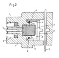
- Fig. 1 shows a section of a pyromechanical disconnecting device for battery shutdown in a motor vehicle with an ignition element 2, which is encapsulated by the housing 1 and thereby forms a structural unit with the housing 1.
- the housing 1 consists of an electrically insulating material such as plastic, in which strength-increasing fillers, in particular glass fibers or carbon fibers, are contained.
- connection pins 5 are not encapsulated by the housing 1 for electrical contacting, but are arranged in a recess 6 of the housing 1 and are in this case formed as a plug 7 or connected to a plug 7.
- a receiving space 8 for receiving a cutting chisel 12 and a conductor rail 11, wherein the current conductor rail 11 is formed by the cutting chisel 12 at a separation point severable.
- the cutting bit 12 is accelerated to the separation point by the propellant gases formed during the ignition of the ignition element 2.
- the cutting bit 12 can be plugged around the Anzündelement 2, a circumferential recess 9 in the housing 1 is arranged in the receiving chamber 8 in the region of the ignition element 2, wherein between the ignition element 2 and the recess 9, an annular projection 10 of the housing 1 is arranged.
- a circumferential groove 3 is arranged, in which a sealing ring 4 is inserted. This circumferential groove 3 is therefore arranged in the annular projection 10 to the recess 9 back.
- the cutting bit 12 is inserted into this recess 9 and thus surrounds the ignition element. 2
Landscapes
- Engineering & Computer Science (AREA)
- Mechanical Engineering (AREA)
- General Engineering & Computer Science (AREA)
- Fuses (AREA)
- Air Bags (AREA)
- Battery Mounting, Suspending (AREA)
- Ignition Installations For Internal Combustion Engines (AREA)
- Connection Of Batteries Or Terminals (AREA)
- Portable Nailing Machines And Staplers (AREA)
- Electric Propulsion And Braking For Vehicles (AREA)
Description
- Die Erfindung betrifft eine pyromechanische Trennvorrichtung nach dem Oberbegriff des Anspruchs 1 (vgl.
US-A-5,877,563 ). - Aus der
DE 43 07 774 A ist eine elektrische Anzündeinrichtung bekannt, bei der ein Aufnahmeteil für einen Zündwiderstand mit Kunststoff umspritzt und in ein Gehäuse eingesetzt ist. - Es ist die Aufgabe der vorliegenden Erfindung, eine pyromechanische Trennvorrichtung der vorstehend genannten Art so weiterzubilden, dass dieses kostengünstig herstellbar ist.
- Die Lösung dieser Aufgabe erfolgt durch die Merkmale des Anspruchs 1.
- Erfindungsgemäß entfällt der komplette Einsetzvorgang des Anzündelements in das Gehäuse.
- Die Umspritzung des Anzündelements hat gleichzeitig die Funktion eines Gehäuses für eine pyromechanische Trennvorrichtung.
- In bevorzugter Ausführungsform besteht das Gehäuse aus einem elektrisch isolierenden Material, insbesondere aus einem Kunststoff.
- Vorteilhafterweise sind im isolierenden Material festigkeitserhöhende Füllstoffe wie Glasfasern oder Kohlenstofffasern angeordnet.
- Erfindungsgemäß sind die Anschlusspins des Anzündelements für eine elektrische Kontaktierung in einer Ausnehmung des Gehäuses angeordnet.
- In einer Ausführungsform sind die Anschlusspins des Anzündelements gegeneinander isoliert. Dies kann auf Grund der Materialeigenschaften des Gehäuses erforderlich sein.
- Erfindungsgemäß weist im Bereich des Anzündelements das Innere des Gehäuses eine umlaufende Ausnehmung zum Aufstecken des Trennmeißels auf.
- In besonderer Ausführungsform ist in der umlaufenden Ausnehmung an der zum Anzündelement gewandten Seite eine umlaufende Nut angeordnet, in der ein Dichtungsring eingelassen ist. Dieser Dichtungsring kann z. B. ein O-Ring sein.
- Nachfolgend wird die Erfindung an Hand von zwei Figuren näher erläutert.
- Fig. 1 zeigt einen Ausschnitt aus einer pyromechanischen Trennvorrichtung zur Batterieabschaltung in einem Kraftfahrzeug mit einem Anzündelement 2, welches vom Gehäuse 1 umspritzt ist und dadurch mit dem Gehäuse 1 eine Baueinheit bildet. Das Gehäuse 1 besteht aus einem elektrisch isolierenden Material wie Kunststoff, in dem festigkeitserhöhende Füllstoffe insbesondere Glasfasern oder Kohlenstofffasern enthalten sind.
- Die Anschlusspins 5 sind für eine elektrische Kontaktierung vom Gehäuse 1 nicht umspritzt, sondern sind in einer Ausnehmung 6 des Gehäuses 1 angeordnet und sind in diesem Fall als Stecker 7 ausgebildet bzw. mit einem Stecker 7 verbunden.
- Im Inneren des Gehäuses 1 (siehe Figur 2) befindet sich ein Aufnahmeraum 8 zur Aufnahme eines Trennmeißels 12 und einer Stromleiterschiene 11, wobei die Stromleiterschiene 11 vom Trennmeißel 12 an einer Trennstelle durchtrennbar ausgebildet ist. Der Trennmeißel 12 wird durch die bei der Anzündung des Anzündelements 2 entstehenden Treibgase auf die Trennstelle beschleunigt.
- Damit der Trennmeißel 12 auf das Anzündelement 2 umgreifend aufgesteckt werden kann, ist im Bereich des Anzündelements 2 im Aufnahmeraum 8 eine umlaufende Ausnehmung 9 im Gehäuse 1 angeordnet, wobei zwischen dem Anzündelement 2 und der Ausnehmung 9 eine ringförmige Auskragung 10 des Gehäuses 1 angeordnet ist. In der umlaufenden Ausnehmung 9 an der zum Anzündelement 2 gewandten Seite ist eine umlaufende Nut 3 angeordnet, in der ein Dichtungsring 4 eingelassen ist. Diese umlaufende Nut 3 ist demnach in der ringförmigen Auskragung 10 zur Ausnehmung 9 hin angeordnet. Der Trennmeißel 12 wird in diese Ausnehmung 9 gesteckt und umgreift damit das Anzündelement 2.
Claims (5)
- Pyromechanische Trennvorrichtung, insbesondere zur Batterieabschaltung in einem Kraftfahrzeug, mit einem Gehäuse (1), in dem eine Stromleiterschiene (11) angeordnet ist, die von einem Trennmeissel (12) an einer Trennstelle durchtrennbar ausgebildet ist, wobei der Trennmeissel (12) durch die Treibgase eines Anzündelements (2) beschleunigbar ist,
dadurch gekennzeichnet, dass
das Anzündelement (2) vom Gehäuse (1) umspritzt ist und dadurch mit dem Gehäuse (1) eine Baueinheit bildet,
dass Anschlusspins (5) des Anzündelements (2) in einer Ausnehmung (6) des Gehäuses (1) angeordnet sind, und
dass im Bereich des Anzündelements (2) das Innere des Gehäuses (1) eine umlaufende Ausnehmung (9) zum Aufstecken des Trennmeissels (12) aufweist, wobei zwischen dem Anzündelement (2) und der Ausnehmung (9) eine ringförmige Auskragung (10) des Gehäuses (1) angeordnet ist. - Trennvorrichtung nach Anspruch 1, dadurch gekennzeichnet, dass das Gehäuse (1) aus einem elektrisch isolierenden Material besteht.
- Trennvorrichtung nach Anspruch 2, dadurch gekennzeichnet, dass im isolierenden Material festigkeitserhöhende Füllstoffe wie Glasfasern oder Kohlenstofffasern angeordnet sind.
- Trennvorrichtung nach einem der Ansprüche 1 bis 3, dadurch gekennzeichnet, dass das Gehäuse (1) aus einem Kunststoff besteht.
- Trennvorrichtung nach Anspruch 1, dadurch gekennzeichnet, dass in der umlaufenden Ausnehmung (9) an der zum Anzündelement (2) gewandten Seite eine umlaufende Nut (3) angeordnet ist, in der ein Dichtungsring (4) eingelassen ist.
Applications Claiming Priority (4)
| Application Number | Priority Date | Filing Date | Title |
|---|---|---|---|
| DE10319749 | 2003-04-30 | ||
| DE10319749 | 2003-04-30 | ||
| DE102004010746A DE102004010746A1 (de) | 2003-04-30 | 2004-03-05 | Gehäuse für ein pyromechanisches Trennelement mit integriertem Anzündelement |
| DE102004010746 | 2004-03-05 |
Publications (2)
| Publication Number | Publication Date |
|---|---|
| EP1473536A1 EP1473536A1 (de) | 2004-11-03 |
| EP1473536B1 true EP1473536B1 (de) | 2007-10-17 |
Family
ID=32991944
Family Applications (1)
| Application Number | Title | Priority Date | Filing Date |
|---|---|---|---|
| EP04009275A Expired - Lifetime EP1473536B1 (de) | 2003-04-30 | 2004-04-20 | Gehäuse für eine pyromechanische Trennvorrichtung mit integriertem Anzündelement |
Country Status (5)
| Country | Link |
|---|---|
| US (1) | US7745745B2 (de) |
| EP (1) | EP1473536B1 (de) |
| JP (1) | JP4249654B2 (de) |
| AT (1) | ATE376163T1 (de) |
| DE (1) | DE502004005237D1 (de) |
Families Citing this family (17)
| Publication number | Priority date | Publication date | Assignee | Title |
|---|---|---|---|---|
| US7557688B2 (en) * | 2003-04-30 | 2009-07-07 | Delphi Technologies, Inc. | Housing configuration for a pyromechanical disconnecting device |
| US9136558B2 (en) * | 2009-08-14 | 2015-09-15 | Philips Plastics Corporation | Impact resistant battery |
| US8709628B2 (en) * | 2010-09-02 | 2014-04-29 | Bathium Canada Inc. | Battery pack with connecting device |
| AT12531U1 (de) * | 2011-05-23 | 2012-07-15 | Hirtenberger Automotive Safety Gmbh & Co Kg | Pyrotechnischer aktuator |
| JP5874583B2 (ja) * | 2012-08-29 | 2016-03-02 | 豊田合成株式会社 | 導通遮断装置 |
| JP2014049300A (ja) * | 2012-08-31 | 2014-03-17 | Toyoda Gosei Co Ltd | 導通遮断装置 |
| EP2811548B1 (de) | 2013-06-07 | 2017-08-09 | Autoliv Development AB | Batteriemodul mit Trennanordnung |
| EP2995822B1 (de) * | 2014-09-09 | 2019-11-13 | Arianegroup Sas | Pyrotechnischer Aktuator |
| JP6409651B2 (ja) * | 2015-03-30 | 2018-10-24 | 豊田合成株式会社 | 導通遮断装置 |
| DE102015107579B3 (de) | 2015-05-13 | 2016-08-04 | Lisa Dräxlmaier GmbH | Sicherung mit Explosionskammer |
| FR3051282B1 (fr) * | 2016-05-16 | 2021-05-21 | Herakles | Dispositif de coupure destine a etre relie a un circuit electrique |
| WO2018038117A1 (ja) | 2016-08-23 | 2018-03-01 | 株式会社ダイセル | アクチュエータ |
| US10549038B2 (en) | 2017-06-29 | 2020-02-04 | Daicel Corporation | Syringe |
| US10332707B2 (en) * | 2017-06-29 | 2019-06-25 | Daicel Corporation | Actuator |
| EP3933878B1 (de) * | 2020-07-03 | 2022-12-14 | Munich Electrification GmbH | Schützvorrichtung, energiespeichersystem und verfahren zur steuerung einer schützvorrichtung |
| JP7329850B2 (ja) * | 2020-12-16 | 2023-08-21 | 太平洋精工株式会社 | 電気回路遮断装置 |
| JP7426618B1 (ja) * | 2022-12-23 | 2024-02-02 | パナソニックIpマネジメント株式会社 | 遮断装置 |
Family Cites Families (10)
| Publication number | Priority date | Publication date | Assignee | Title |
|---|---|---|---|---|
| US3794794A (en) * | 1972-11-10 | 1974-02-26 | Ford Motor Co | Impact responsive switch with frangible element holding contact plunger in unactivated position |
| US4224487A (en) * | 1978-02-23 | 1980-09-23 | Simonsen Bent P | Fast acting explosive circuit interrupter |
| US4417519A (en) * | 1981-06-04 | 1983-11-29 | Mcdonnell Douglas Corporation | Explosive switch |
| US5535842A (en) * | 1993-03-05 | 1996-07-16 | Volkswagen Ag | Safety arrangement for collision-related disconnection of an electrical energy source from a motor vehicle supply circuit |
| DE4307774A1 (de) * | 1993-03-12 | 1994-09-15 | Dynamit Nobel Ag | Anzündeinrichtung |
| DE19503809B4 (de) * | 1995-02-06 | 2005-01-20 | Bayerische Motoren Werke Ag | Sicherungsvorrichtung für eine Stromleitung in Fahrzeugen |
| DE19616993A1 (de) * | 1996-04-27 | 1997-10-30 | Dynamit Nobel Ag | Pyrotechnisches Sicherungselement für Stromkreise |
| US6419263B1 (en) * | 1998-05-11 | 2002-07-16 | The B. F. Goodrich Company | Seatbelt system having seamless inflatable member |
| DE19728658A1 (de) * | 1997-07-04 | 1999-01-07 | Dynamit Nobel Ag | Pyrotechnisches Wirkelement |
| JP3426508B2 (ja) * | 1998-06-30 | 2003-07-14 | 矢崎総業株式会社 | 低融点材溶断装置及び回路遮断装置 |
-
2004
- 2004-04-20 EP EP04009275A patent/EP1473536B1/de not_active Expired - Lifetime
- 2004-04-20 DE DE502004005237T patent/DE502004005237D1/de not_active Expired - Lifetime
- 2004-04-20 AT AT04009275T patent/ATE376163T1/de not_active IP Right Cessation
- 2004-04-30 JP JP2004136220A patent/JP4249654B2/ja not_active Expired - Fee Related
- 2004-04-30 US US10/835,065 patent/US7745745B2/en not_active Expired - Fee Related
Also Published As
| Publication number | Publication date |
|---|---|
| US7745745B2 (en) | 2010-06-29 |
| JP2004331057A (ja) | 2004-11-25 |
| ATE376163T1 (de) | 2007-11-15 |
| JP4249654B2 (ja) | 2009-04-02 |
| US20050034595A1 (en) | 2005-02-17 |
| DE502004005237D1 (de) | 2007-11-29 |
| EP1473536A1 (de) | 2004-11-03 |
Similar Documents
| Publication | Publication Date | Title |
|---|---|---|
| EP1473536A1 (de) | Gehäuse für eine pyromechanische Trennvorrichtung mit integriertem Anzündelement | |
| EP1464544B1 (de) | Gehäuse mit Stromleiterschiene für eine Trennvorrichtung | |
| DE102020203081A1 (de) | Dichtungsanordnung zur statischen Abdichtung einer vereisungsgefährdeten Bauteilkomponente, Objektiv mit Dichtungsanordnung | |
| EP2012082A2 (de) | Metall/Fixiermaterial-Sockel für Zündvorrichtungen von Airbags oder dergleichen Personenschutzeinrichtungen, insbesondere bei Kraftfahrzeugen sowie Zündvorrichtung mit einem derartigen Sockel | |
| EP1492139A1 (de) | Meissel für ein pyromechanisches Trennelement | |
| EP1588392A1 (de) | Gehäuse und stromleiterschiene für eine batterieabschaltung | |
| EP3525223B1 (de) | Pyrotechnischer schalter | |
| EP1070642A2 (de) | Heizvorrichtung für Scheibenwaschanlage | |
| EP2020013A1 (de) | Verfahren und vorrichtung zur einmaligen und dauerhaften trennung einer elektrischen verbindung, insbesondere in einem kraftfahrzeug | |
| EP3657566B1 (de) | Steckervorrichtung für eine batterie, batterie und kraftfahrzeug | |
| DE102017217917A1 (de) | Speichereinrichtung zum Speichern von elektrischer Energie für ein Kraftfahrzeug, sowie Verfahren zum Trennen zweier Gehäuseelemente einer solchen Speichereinrichtung | |
| DE10303377A1 (de) | Pyromechanisches Trennelement | |
| DE102017109209A1 (de) | Anzünderträger, baugruppe, gasgenerator sowie verfahren zur herstellung eines gasgenerators | |
| EP0883789B1 (de) | Gasgenerator, insbesondere für gurtstraffer | |
| DE60211462T2 (de) | Pyrotechnischer elektrischer Anzünder und Montageverfahren | |
| DE102006032605A1 (de) | Verfahren und Vorrichtung zur einmaligen und dauerhaften Trennung einer elektrischen Verbindung, insbesondere in einem Kraftfahrzeug | |
| DE102004010746A1 (de) | Gehäuse für ein pyromechanisches Trennelement mit integriertem Anzündelement | |
| DE102012004966B3 (de) | Zündsockel für pyroelektrische Zündvorrichtungen | |
| DE102017221025A1 (de) | Verbindungsmittel zur elektrischen Verbindung elektrischer Leitungen | |
| EP0793244B1 (de) | Elektrischer Kondensator | |
| DE2644664A1 (de) | Elektrische fassung und verfahren zu ihrer herstellung | |
| WO2004097877A1 (de) | Gehäuseausführung für eine pyromechanische trennvorrichtung | |
| EP1733929A2 (de) | Direktintegration der steckseitigen Schnittstelle in die Gasgeneratorgeometrie | |
| DE202004011348U1 (de) | Zündeinrichtung für einen Gasgenerator | |
| DE102009008389A1 (de) | Kraftfahrzeugenergieleiter mit einem Übergabestützpunkt |
Legal Events
| Date | Code | Title | Description |
|---|---|---|---|
| PUAI | Public reference made under article 153(3) epc to a published international application that has entered the european phase |
Free format text: ORIGINAL CODE: 0009012 |
|
| AK | Designated contracting states |
Kind code of ref document: A1 Designated state(s): AT BE BG CH CY CZ DE DK EE ES FI FR GB GR HU IE IT LI LU MC NL PL PT RO SE SI SK TR |
|
| AX | Request for extension of the european patent |
Extension state: AL HR LT LV MK |
|
| RAP1 | Party data changed (applicant data changed or rights of an application transferred) |
Owner name: DELPHI TECHNOLOGIES, INC. |
|
| 17P | Request for examination filed |
Effective date: 20050503 |
|
| AKX | Designation fees paid |
Designated state(s): AT BE BG CH CY CZ DE DK EE ES FI FR GB GR HU IE IT LI LU MC NL PL PT RO SE SI SK TR |
|
| GRAP | Despatch of communication of intention to grant a patent |
Free format text: ORIGINAL CODE: EPIDOSNIGR1 |
|
| GRAS | Grant fee paid |
Free format text: ORIGINAL CODE: EPIDOSNIGR3 |
|
| GRAA | (expected) grant |
Free format text: ORIGINAL CODE: 0009210 |
|
| AK | Designated contracting states |
Kind code of ref document: B1 Designated state(s): AT BE BG CH CY CZ DE DK EE ES FI FR GB GR HU IE IT LI LU MC NL PL PT RO SE SI SK TR |
|
| REG | Reference to a national code |
Ref country code: GB Ref legal event code: FG4D Free format text: NOT ENGLISH |
|
| REG | Reference to a national code |
Ref country code: CH Ref legal event code: EP |
|
| REG | Reference to a national code |
Ref country code: IE Ref legal event code: FG4D Free format text: LANGUAGE OF EP DOCUMENT: GERMAN |
|
| REF | Corresponds to: |
Ref document number: 502004005237 Country of ref document: DE Date of ref document: 20071129 Kind code of ref document: P |
|
| ET | Fr: translation filed | ||
| NLV1 | Nl: lapsed or annulled due to failure to fulfill the requirements of art. 29p and 29m of the patents act | ||
| PG25 | Lapsed in a contracting state [announced via postgrant information from national office to epo] |
Ref country code: NL Free format text: LAPSE BECAUSE OF FAILURE TO SUBMIT A TRANSLATION OF THE DESCRIPTION OR TO PAY THE FEE WITHIN THE PRESCRIBED TIME-LIMIT Effective date: 20071017 Ref country code: ES Free format text: LAPSE BECAUSE OF FAILURE TO SUBMIT A TRANSLATION OF THE DESCRIPTION OR TO PAY THE FEE WITHIN THE PRESCRIBED TIME-LIMIT Effective date: 20080128 Ref country code: SE Free format text: LAPSE BECAUSE OF FAILURE TO SUBMIT A TRANSLATION OF THE DESCRIPTION OR TO PAY THE FEE WITHIN THE PRESCRIBED TIME-LIMIT Effective date: 20080117 |
|
| GBV | Gb: ep patent (uk) treated as always having been void in accordance with gb section 77(7)/1977 [no translation filed] | ||
| PG25 | Lapsed in a contracting state [announced via postgrant information from national office to epo] |
Ref country code: PL Free format text: LAPSE BECAUSE OF FAILURE TO SUBMIT A TRANSLATION OF THE DESCRIPTION OR TO PAY THE FEE WITHIN THE PRESCRIBED TIME-LIMIT Effective date: 20071017 Ref country code: PT Free format text: LAPSE BECAUSE OF FAILURE TO SUBMIT A TRANSLATION OF THE DESCRIPTION OR TO PAY THE FEE WITHIN THE PRESCRIBED TIME-LIMIT Effective date: 20080317 Ref country code: BG Free format text: LAPSE BECAUSE OF FAILURE TO SUBMIT A TRANSLATION OF THE DESCRIPTION OR TO PAY THE FEE WITHIN THE PRESCRIBED TIME-LIMIT Effective date: 20080117 Ref country code: SI Free format text: LAPSE BECAUSE OF FAILURE TO SUBMIT A TRANSLATION OF THE DESCRIPTION OR TO PAY THE FEE WITHIN THE PRESCRIBED TIME-LIMIT Effective date: 20071017 |
|
| REG | Reference to a national code |
Ref country code: IE Ref legal event code: FD4D |
|
| PG25 | Lapsed in a contracting state [announced via postgrant information from national office to epo] |
Ref country code: DK Free format text: LAPSE BECAUSE OF FAILURE TO SUBMIT A TRANSLATION OF THE DESCRIPTION OR TO PAY THE FEE WITHIN THE PRESCRIBED TIME-LIMIT Effective date: 20071017 Ref country code: CZ Free format text: LAPSE BECAUSE OF FAILURE TO SUBMIT A TRANSLATION OF THE DESCRIPTION OR TO PAY THE FEE WITHIN THE PRESCRIBED TIME-LIMIT Effective date: 20071017 |
|
| PLBE | No opposition filed within time limit |
Free format text: ORIGINAL CODE: 0009261 |
|
| STAA | Information on the status of an ep patent application or granted ep patent |
Free format text: STATUS: NO OPPOSITION FILED WITHIN TIME LIMIT |
|
| PG25 | Lapsed in a contracting state [announced via postgrant information from national office to epo] |
Ref country code: SK Free format text: LAPSE BECAUSE OF FAILURE TO SUBMIT A TRANSLATION OF THE DESCRIPTION OR TO PAY THE FEE WITHIN THE PRESCRIBED TIME-LIMIT Effective date: 20071017 Ref country code: RO Free format text: LAPSE BECAUSE OF FAILURE TO SUBMIT A TRANSLATION OF THE DESCRIPTION OR TO PAY THE FEE WITHIN THE PRESCRIBED TIME-LIMIT Effective date: 20071017 |
|
| 26N | No opposition filed |
Effective date: 20080718 |
|
| BERE | Be: lapsed |
Owner name: DELPHI TECHNOLOGIES, INC. Effective date: 20080430 |
|
| PG25 | Lapsed in a contracting state [announced via postgrant information from national office to epo] |
Ref country code: IE Free format text: LAPSE BECAUSE OF FAILURE TO SUBMIT A TRANSLATION OF THE DESCRIPTION OR TO PAY THE FEE WITHIN THE PRESCRIBED TIME-LIMIT Effective date: 20071017 |
|
| PG25 | Lapsed in a contracting state [announced via postgrant information from national office to epo] |
Ref country code: GB Free format text: LAPSE BECAUSE OF FAILURE TO SUBMIT A TRANSLATION OF THE DESCRIPTION OR TO PAY THE FEE WITHIN THE PRESCRIBED TIME-LIMIT Effective date: 20071017 Ref country code: MC Free format text: LAPSE BECAUSE OF NON-PAYMENT OF DUE FEES Effective date: 20080430 |
|
| REG | Reference to a national code |
Ref country code: CH Ref legal event code: PL |
|
| PG25 | Lapsed in a contracting state [announced via postgrant information from national office to epo] |
Ref country code: CH Free format text: LAPSE BECAUSE OF NON-PAYMENT OF DUE FEES Effective date: 20080430 Ref country code: LI Free format text: LAPSE BECAUSE OF NON-PAYMENT OF DUE FEES Effective date: 20080430 Ref country code: EE Free format text: LAPSE BECAUSE OF FAILURE TO SUBMIT A TRANSLATION OF THE DESCRIPTION OR TO PAY THE FEE WITHIN THE PRESCRIBED TIME-LIMIT Effective date: 20071017 Ref country code: GR Free format text: LAPSE BECAUSE OF FAILURE TO SUBMIT A TRANSLATION OF THE DESCRIPTION OR TO PAY THE FEE WITHIN THE PRESCRIBED TIME-LIMIT Effective date: 20080118 |
|
| PG25 | Lapsed in a contracting state [announced via postgrant information from national office to epo] |
Ref country code: FI Free format text: LAPSE BECAUSE OF FAILURE TO SUBMIT A TRANSLATION OF THE DESCRIPTION OR TO PAY THE FEE WITHIN THE PRESCRIBED TIME-LIMIT Effective date: 20071017 |
|
| PG25 | Lapsed in a contracting state [announced via postgrant information from national office to epo] |
Ref country code: BE Free format text: LAPSE BECAUSE OF NON-PAYMENT OF DUE FEES Effective date: 20080430 |
|
| PG25 | Lapsed in a contracting state [announced via postgrant information from national office to epo] |
Ref country code: CY Free format text: LAPSE BECAUSE OF FAILURE TO SUBMIT A TRANSLATION OF THE DESCRIPTION OR TO PAY THE FEE WITHIN THE PRESCRIBED TIME-LIMIT Effective date: 20071017 |
|
| PG25 | Lapsed in a contracting state [announced via postgrant information from national office to epo] |
Ref country code: AT Free format text: LAPSE BECAUSE OF NON-PAYMENT OF DUE FEES Effective date: 20080420 |
|
| PG25 | Lapsed in a contracting state [announced via postgrant information from national office to epo] |
Ref country code: HU Free format text: LAPSE BECAUSE OF FAILURE TO SUBMIT A TRANSLATION OF THE DESCRIPTION OR TO PAY THE FEE WITHIN THE PRESCRIBED TIME-LIMIT Effective date: 20080418 Ref country code: LU Free format text: LAPSE BECAUSE OF NON-PAYMENT OF DUE FEES Effective date: 20080420 |
|
| PG25 | Lapsed in a contracting state [announced via postgrant information from national office to epo] |
Ref country code: TR Free format text: LAPSE BECAUSE OF FAILURE TO SUBMIT A TRANSLATION OF THE DESCRIPTION OR TO PAY THE FEE WITHIN THE PRESCRIBED TIME-LIMIT Effective date: 20071017 |
|
| PGFP | Annual fee paid to national office [announced via postgrant information from national office to epo] |
Ref country code: IT Payment date: 20110422 Year of fee payment: 8 |
|
| REG | Reference to a national code |
Ref country code: FR Ref legal event code: TP Owner name: AUTOLIV DEVELOPMENT AB, SE Effective date: 20120514 |
|
| PG25 | Lapsed in a contracting state [announced via postgrant information from national office to epo] |
Ref country code: IT Free format text: LAPSE BECAUSE OF NON-PAYMENT OF DUE FEES Effective date: 20120420 |
|
| REG | Reference to a national code |
Ref country code: FR Ref legal event code: PLFP Year of fee payment: 13 |
|
| REG | Reference to a national code |
Ref country code: FR Ref legal event code: PLFP Year of fee payment: 14 |
|
| PGFP | Annual fee paid to national office [announced via postgrant information from national office to epo] |
Ref country code: DE Payment date: 20170426 Year of fee payment: 14 |
|
| REG | Reference to a national code |
Ref country code: FR Ref legal event code: PLFP Year of fee payment: 15 |
|
| REG | Reference to a national code |
Ref country code: DE Ref legal event code: R119 Ref document number: 502004005237 Country of ref document: DE |
|
| PG25 | Lapsed in a contracting state [announced via postgrant information from national office to epo] |
Ref country code: DE Free format text: LAPSE BECAUSE OF NON-PAYMENT OF DUE FEES Effective date: 20181101 |
|
| PG25 | Lapsed in a contracting state [announced via postgrant information from national office to epo] |
Ref country code: FR Free format text: LAPSE BECAUSE OF NON-PAYMENT OF DUE FEES Effective date: 20200430 |
|
| PG25 | Lapsed in a contracting state [announced via postgrant information from national office to epo] |
Ref country code: FR Free format text: LAPSE BECAUSE OF NON-PAYMENT OF DUE FEES Effective date: 20200430 |
|
| PGRI | Patent reinstated in contracting state [announced from national office to epo] |
Ref country code: FR Effective date: 20210318 |
|
| PGFP | Annual fee paid to national office [announced via postgrant information from national office to epo] |
Ref country code: FR Payment date: 20230424 Year of fee payment: 20 |