EP1473512A2 - Leuchte - Google Patents
Leuchte Download PDFInfo
- Publication number
- EP1473512A2 EP1473512A2 EP04010192A EP04010192A EP1473512A2 EP 1473512 A2 EP1473512 A2 EP 1473512A2 EP 04010192 A EP04010192 A EP 04010192A EP 04010192 A EP04010192 A EP 04010192A EP 1473512 A2 EP1473512 A2 EP 1473512A2
- Authority
- EP
- European Patent Office
- Prior art keywords
- lamp
- luminaire according
- diffuser
- reflector
- transparent plates
- Prior art date
- Legal status (The legal status is an assumption and is not a legal conclusion. Google has not performed a legal analysis and makes no representation as to the accuracy of the status listed.)
- Granted
Links
- 229920003229 poly(methyl methacrylate) Polymers 0.000 claims description 7
- 239000004926 polymethyl methacrylate Substances 0.000 claims description 7
- 238000009826 distribution Methods 0.000 claims description 6
- 239000004417 polycarbonate Substances 0.000 claims description 3
- 229920000515 polycarbonate Polymers 0.000 claims description 3
- 238000002834 transmittance Methods 0.000 claims 1
- 230000000694 effects Effects 0.000 description 6
- 238000004519 manufacturing process Methods 0.000 description 6
- 238000002788 crimping Methods 0.000 description 3
- 239000002184 metal Substances 0.000 description 3
- 238000003860 storage Methods 0.000 description 3
- 230000004313 glare Effects 0.000 description 2
- 238000009434 installation Methods 0.000 description 2
- 239000000463 material Substances 0.000 description 2
- 230000003287 optical effect Effects 0.000 description 2
- 230000005540 biological transmission Effects 0.000 description 1
- 238000004061 bleaching Methods 0.000 description 1
- 230000001419 dependent effect Effects 0.000 description 1
- 238000011161 development Methods 0.000 description 1
- 230000018109 developmental process Effects 0.000 description 1
- 239000011888 foil Substances 0.000 description 1
- 238000001746 injection moulding Methods 0.000 description 1
- 230000005855 radiation Effects 0.000 description 1
- 239000000243 solution Substances 0.000 description 1
Images

Classifications
-
- F—MECHANICAL ENGINEERING; LIGHTING; HEATING; WEAPONS; BLASTING
- F21—LIGHTING
- F21V—FUNCTIONAL FEATURES OR DETAILS OF LIGHTING DEVICES OR SYSTEMS THEREOF; STRUCTURAL COMBINATIONS OF LIGHTING DEVICES WITH OTHER ARTICLES, NOT OTHERWISE PROVIDED FOR
- F21V17/00—Fastening of component parts of lighting devices, e.g. shades, globes, refractors, reflectors, filters, screens, grids or protective cages
- F21V17/10—Fastening of component parts of lighting devices, e.g. shades, globes, refractors, reflectors, filters, screens, grids or protective cages characterised by specific fastening means or way of fastening
- F21V17/16—Fastening of component parts of lighting devices, e.g. shades, globes, refractors, reflectors, filters, screens, grids or protective cages characterised by specific fastening means or way of fastening by deformation of parts; Snap action mounting
-
- F—MECHANICAL ENGINEERING; LIGHTING; HEATING; WEAPONS; BLASTING
- F21—LIGHTING
- F21S—NON-PORTABLE LIGHTING DEVICES; SYSTEMS THEREOF; VEHICLE LIGHTING DEVICES SPECIALLY ADAPTED FOR VEHICLE EXTERIORS
- F21S8/00—Lighting devices intended for fixed installation
- F21S8/02—Lighting devices intended for fixed installation of recess-mounted type, e.g. downlighters
-
- F—MECHANICAL ENGINEERING; LIGHTING; HEATING; WEAPONS; BLASTING
- F21—LIGHTING
- F21V—FUNCTIONAL FEATURES OR DETAILS OF LIGHTING DEVICES OR SYSTEMS THEREOF; STRUCTURAL COMBINATIONS OF LIGHTING DEVICES WITH OTHER ARTICLES, NOT OTHERWISE PROVIDED FOR
- F21V13/00—Producing particular characteristics or distribution of the light emitted by means of a combination of elements specified in two or more of main groups F21V1/00 - F21V11/00
- F21V13/12—Combinations of only three kinds of elements
-
- F—MECHANICAL ENGINEERING; LIGHTING; HEATING; WEAPONS; BLASTING
- F21—LIGHTING
- F21V—FUNCTIONAL FEATURES OR DETAILS OF LIGHTING DEVICES OR SYSTEMS THEREOF; STRUCTURAL COMBINATIONS OF LIGHTING DEVICES WITH OTHER ARTICLES, NOT OTHERWISE PROVIDED FOR
- F21V11/00—Screens not covered by groups F21V1/00, F21V3/00, F21V7/00 or F21V9/00
- F21V11/02—Screens not covered by groups F21V1/00, F21V3/00, F21V7/00 or F21V9/00 using parallel laminae or strips, e.g. of Venetian-blind type
-
- F—MECHANICAL ENGINEERING; LIGHTING; HEATING; WEAPONS; BLASTING
- F21—LIGHTING
- F21V—FUNCTIONAL FEATURES OR DETAILS OF LIGHTING DEVICES OR SYSTEMS THEREOF; STRUCTURAL COMBINATIONS OF LIGHTING DEVICES WITH OTHER ARTICLES, NOT OTHERWISE PROVIDED FOR
- F21V11/00—Screens not covered by groups F21V1/00, F21V3/00, F21V7/00 or F21V9/00
- F21V11/08—Screens not covered by groups F21V1/00, F21V3/00, F21V7/00 or F21V9/00 using diaphragms containing one or more apertures
- F21V11/14—Screens not covered by groups F21V1/00, F21V3/00, F21V7/00 or F21V9/00 using diaphragms containing one or more apertures with many small apertures
-
- F—MECHANICAL ENGINEERING; LIGHTING; HEATING; WEAPONS; BLASTING
- F21—LIGHTING
- F21V—FUNCTIONAL FEATURES OR DETAILS OF LIGHTING DEVICES OR SYSTEMS THEREOF; STRUCTURAL COMBINATIONS OF LIGHTING DEVICES WITH OTHER ARTICLES, NOT OTHERWISE PROVIDED FOR
- F21V3/00—Globes; Bowls; Cover glasses
- F21V3/04—Globes; Bowls; Cover glasses characterised by materials, surface treatments or coatings
-
- F—MECHANICAL ENGINEERING; LIGHTING; HEATING; WEAPONS; BLASTING
- F21—LIGHTING
- F21W—INDEXING SCHEME ASSOCIATED WITH SUBCLASSES F21K, F21L, F21S and F21V, RELATING TO USES OR APPLICATIONS OF LIGHTING DEVICES OR SYSTEMS
- F21W2131/00—Use or application of lighting devices or systems not provided for in codes F21W2102/00-F21W2121/00
- F21W2131/40—Lighting for industrial, commercial, recreational or military use
- F21W2131/402—Lighting for industrial, commercial, recreational or military use for working places
-
- F—MECHANICAL ENGINEERING; LIGHTING; HEATING; WEAPONS; BLASTING
- F21—LIGHTING
- F21Y—INDEXING SCHEME ASSOCIATED WITH SUBCLASSES F21K, F21L, F21S and F21V, RELATING TO THE FORM OR THE KIND OF THE LIGHT SOURCES OR OF THE COLOUR OF THE LIGHT EMITTED
- F21Y2103/00—Elongate light sources, e.g. fluorescent tubes
Definitions
- the present invention relates to a lamp with a tubular Gas discharge lamp and a concave curved reflector in front of a Partially translucent diffuser is arranged.
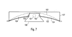
- a lamp of this type is, for example, from WO 01/59364 A1 by the applicant is known and will be briefly explained below with reference to FIG. 7.
- the individual elements of the lamp are inside a box-shaped Luminaire housing 107 arranged when mounting the lamp in the ceiling of a room to be illuminated is sunk.
- a rod-shaped serves as the light source Gas discharge lamp 101, under or - seen in the direction of radiation - in front of the one grid 106 consisting of side reflectors and transverse slats is arranged. The The majority of the light emitted by the lamp 101 is converted via this grid 106 radiated downwards.
- the gas discharge lamp 101 is emitted by a concave reflector 102 spanned, the side wings arranged substantially next to the lamp 101 are.
- a diffuser 103 is further arranged, the two common with the reflector 102 includes so-called light chambers 104.
- the diffuser 103 and the Reflector 102 together at their ends remote from lamp 101.
- a part of the light emitted by the lamp 101 is transmitted via the Reference numerals 105 provided so-called light entry surfaces in the Light chambers 104 coupled in and emitted downwards via the diffuser 103. This also makes the area of the luminaire surrounding the grid 106 light brightened, which creates a visually appealing lighting effect.
- the diffuser 103 is formed by a one-piece component formed, which - as shown in Fig. 7 - is curved in both side regions and has a central bend, which the two curved side areas connects with each other.
- a component can for example be made of PMMA Injection molding processes are manufactured.
- This one-piece design of the diffuser is, however, disadvantageous viewed as the possibilities to change the dimensions of the lamp, are restricted by this.
- the reason for this is that to manufacture the one-piece diffuser a specially prefabricated tool is required, which exclusively for the manufacture of the diffuser with the specified dimensions suitable is. If you want to create a luminaire with different dimensions, do so would need another tool to create a diffuser with the new ones Dimensions are provided, but this reduces the manufacturing costs for the Overall lamp would be significantly increased.
- the one-piece diffuser in the special form shown only made of polymethyl methacrylate (PMMA) can be.
- PMMA polymethyl methacrylate
- PC polycarbonate
- the present invention is therefore based on the object of a lamp to create the type described above with the same lighting effects can be achieved as in the known lamp, but the previously mentioned disadvantages can be avoided.
- the lamp according to the invention initially has a tubular Gas discharge lamp and at least one - from the area to be illuminated seen - on both sides next to the lamp arranged concavely curved Reflector. There is also a next to the lamp but in front of the reflector arranged partially translucent diffuser provided. This consists of two separate transparent plates that can be detached on both sides next to the lamp Fasteners of the lamp are connected.
- the two diffuser disc halves are thus no longer connected in one piece, but instead are available individually, being simple by using suitable fasteners Can be arranged in the desired position. Because the effort to Production of these individual transparent plates is however considerably less than the one for producing the one-piece diffuser part described above, can Diffuser plates in different dimensions are easily provided become. The possibilities of lights in different sizes and dimensions are significantly increased.
- the transparent plates forming the diffuser can also be used in a simple manner just be trained. This will make production of the Diffuser allows, because the diffuser discs simply from a larger plate in the corresponding dimensions can be cut. The Manufacturing costs for the lamp can be considerably reduced become.
- the reflector has on its outer edge a support surface facing the lamp exhibit. This can be done, for example, by appropriate crimping of the Reflector edge can be achieved.
- a special spring element provided, which also has a bearing surface on a side deflectable spring arm is attached. The installation of the diffuser plates on the lamp is thereby greatly simplified since the plate only against the spring element must be pressed and then on the outer edge of the crimping of the Reflector can be placed. Then the spring element again relieved, the diffuser plate is simple but safe in the desired Position held.
- the lamp can - seen from the area to be illuminated - in front of the lamp furthermore have a light distribution element, which is, for example, a Grid or a partially translucent perforated plate can act.
- a light distribution element which is, for example, a Grid or a partially translucent perforated plate can act.
- this additional light distribution element is also on the previously described Fastening springs for the transparent diffuser plates attached.
- the diffuser and the reflector form in an analogous manner to the known luminaire two light chambers arranged to the side of the lamp, the ratio of Width of a chamber to the greatest distance between the reflector and the Diffuser is at least 4: 1 and particularly preferably in the range between 4: 1 and 5: 1. This makes a very flat lamp with very good lighting properties created.
- the reflector is preferably made of two concavely curved reflector parts formed, extending from the center of the lamp to one side of the Extend the luminaire housing.
- Figures 1 to 3 show an embodiment of a lamp according to the invention a recessed ceiling light, the elements of which are in a box-shaped Luminaire housing 7 are arranged, which with the help of mounting elements 9 in the Ceiling of a room to be illuminated is sunk.
- a recessed ceiling light the elements of which are in a box-shaped Luminaire housing 7 are arranged, which with the help of mounting elements 9 in the Ceiling of a room to be illuminated is sunk.
- a large part of the the gas discharge lamps 1 - which are preferably fluorescent lamps acts - emitted light emitted downwards via the grid 6, the Shapes of the grid 6 are chosen so that the light emitted downwards cross-glare to a certain degree.
- the lamp according to the invention is thus especially suitable for lighting rooms with VDU workstations, because Glare effects on screen surfaces and for people present in the room are largely avoided.
- a perforated plate which is backed with foils, for example, or other optical elements are used, for example diffusers or Prism structures.
- a single lamp to the illustrated two-lamp version of the lamp use.
- a reflector On both sides next to the lamp there is a reflector, which is actually is formed from two concavely curved reflectors 2, which extend from the center of the Extend the luminaire housing to the outside.
- a diffuser plate 3 In front of the reflectors 2 is in each case a diffuser plate 3 is arranged.
- the reflectors 2 and diffuser plates 3 run each at their ends remote from the lamps 1 and thus close two light chambers 4 arranged on both sides next to the lamps 1.
- the Light entry surfaces for the two light chambers 4 are each of the Upper edge of the grid 6 and the reflectors 2 limited. Because the diffuser plates 3 each up to the upper edge of the corresponding side wall of the grid 6 extends, it is avoided that the lamps 1 arranged above the grid 6 can be viewed directly from the side and thus glare effects arise.
- the width a of the light chambers 4 is preferably at least four times as large the height b of the light chambers 4, i.e. the distance between one Light entry area and the outer end of a light chamber 4 is larger than that Four times the greatest distance between the reflector 2 and the diffuser 3. Die This makes the luminaire very flat and elegant.
- the Size ratio between width a and height b of a light chamber 4 is particularly preferably in the range between 4: 1 and 5: 1.
- the diffusers 3 on both sides of the lamps 1 despite the low height of the luminaire over its entire width in one uniform brightness appear.
- the one shown here contributes to this curved shape of the reflectors 2, which have a corresponding light control causes light rays coupled into the light chamber 4, on the other hand can Additional measures may be provided to achieve the desired level To achieve luminance.
- the reflectors 2 could be configured in this way be that they unite in the outer areas away from the lamps 1 have a higher degree of reflection than in the immediate vicinity of the lamps 1.
- the diffusers 3 could also be in the outer Areas have a higher light transmission.
- the area behind the reflectors 2 within the luminaire housing 7 can be used, for example, to arrange the control devices for the lamps 1 be used. As shown in Fig. 1, for example, on the An electronic ballast 8 can be arranged on the bottom side of the housing 7.
- the reflectors 2 trained to be partially translucent and in the ones behind the reflectors Arrange areas of additional lamps, creating additional lighting effects can be achieved. This possibility is detailed in WO 01/59364 A1 described. Generally it should be pointed out that all in the Variants described for WO 01/59364 A1 for the arrangement of lamps and Use of partially transparent or colored optical elements also with the present luminaire according to the invention can be realized.
- the special feature of the lamp according to the invention is in the Realization and storage of the diffuser discs 3. According to the present Invention, these are two separate transparent disks that pass through special fasteners are held in the lamp.
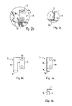
- the storage of the Diffuser discs 3, which will now be explained, can in particular the 2a and 2b are taken.
- the diffuser plate 3 lies on with its outer edge an inward contact surface 2a.
- This contact surface is through a flange of the reflector 2 is formed, so that a holder of the Plates 3 on the respective outside in a simple manner and without the Need for additional measures.
- FIGS. 4a and 4b 4c shows a punched-out bleaching part which forms a Fastening spring 5 is deformed.
- a fastening spring 5 consists of three parts, a base 5a, a side surface forming a spring arm 5b and a support surface 5c.
- the base 5a has two bores 5d, which attach the Fastening springs 5 on the lamp housing 7 via two screws 10 enable, as shown in Figures 1, 2b and 3.
- Perpendicular is angled to the base 5a but also aligned vertically Arranged spring arm 5b, on the underside of which a support surface 5c is formed, which in turn is perpendicular to the two previously mentioned surfaces 5a and 5b is aligned.
- the sheet metal part shown in Fig. 3c is integrally formed and can along the shown fold lines easily deformed to the final shape become.
- the Spring arm 5b are then laterally deflected in the direction of the arrow (see FIG. 4a), so that a simple hanging of the diffuser plate 3 as shown in Fig. 2b is made possible.
- a diffuser plate 3 then takes place in that the plate 3 initially is pressed against the spring element 5 such that the spring arm 5b follows bends inside.
- the outer edge of the diffuser plate 3 is then crimped of the reflector 2a and then the spring arm 5b is relieved, whereby the plate 3 is clipped into the desired position in a simple manner.
- the fastening spring 5 is not only the Holding the diffuser plates 3 is used.
- the mounting springs 5 also serve to hold the grid 6.
- the grid 6 has one in its end regions of the side reflectors suitable profiling with a recess 6a, with the help of which Clamping effect achieved with the mounting springs 5. Because the side walls of the grid 6 are even slightly resilient, the grid 6 can be installed after the Diffuser plates 3 in a simple manner from the bottom to the spring elements 5 be clipped on.
- the diffuser plates 3 are designed as flat plates in the example shown, so that they can be manufactured in a particularly simple and inexpensive manner. However, it would also be conceivable to have the plates curved in a slightly concave manner Provide form. The assembly of the concave curved plates in the lamp would again be done in the same way as previously described.
- a material for the diffuser plates can both polymethyl methacrylate (PMMA) and Polycarbonate (PC) can be used.
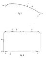
- FIG. 5 shows a reflector 2 seen in section on its own. This exists essentially from three areas, firstly the concavely curved Central area 2b, the outer area 2c with the crimping 2a and one Indoor area 2d.
- FIG. 6 shows a punched-out sheet metal part which corresponds to that in FIG. 5 shown reflector can be deformed.
- the two slots 12 in the interior 2d of the reflector which is easy to install of the reflector in the luminaire.
- two T-type are formed Retaining clips 11 are provided, which - as shown in FIGS. 1 and 3 - along the Middle of the bottom of the lamp housing 7 above the lamps 1 are attached.
- the present invention thus creates a lamp which has the same lighting properties as the known luminaire. Also the appearance of the lamp according to the invention essentially the same already known lamp, but the lamp according to the present Invention can be manufactured much easier and cheaper.
- the solution according to the invention of using two separate diffuser plates facilitates i.a. also the mounting of the plates in the luminaire housing.
Landscapes
- Engineering & Computer Science (AREA)
- General Engineering & Computer Science (AREA)
- Securing Globes, Refractors, Reflectors Or The Like (AREA)
- Non-Portable Lighting Devices Or Systems Thereof (AREA)
- Fastening Of Light Sources Or Lamp Holders (AREA)
Abstract
Description
- Fig. 1
- eine erfindungsgemäße Leuchte im Schnitt;
- Fig. 2a und 2b
- Vergrößerungen zweier Ausschnitte A und B aus Fig. 1;
- Fig. 3
- die in Fig. 1 dargestellte Leuchte im seitlichen Schnitt;
- Fig. 4a bis 4c
- verschiedene Ansichten einer Befestigungsfeder zur Halterung der Diffusorplatten;
- Fig. 5
- die Kontur eines bei der erfindungsgemäßen Leuchte verwendeten Reflektors;
- Fig. 6
- ein Blechteil zur Bildung des in Fig. 5 dargestellten Reflektors; und
- Fig. 7
- eine bekannte Leuchte im Schnitt.
Claims (20)
- Leuchte mit zumindest einer rohrförmigen Gasentladungslampe (1), mindestes einem - von dem zu beleuchtenden Bereich aus gesehen - zu beiden Seiten neben der Lampe (1) angeordneten konkav gekrümmten Reflektor (2) sowie mindestens einem - ebenfalls von dem zu beleuchtenden Bereich aus gesehen - neben der Lampe (1) aber vor dem Reflektor (2) angeordneten zumindest teillichtdurchlässigen Diffusor (3),
dadurch gekennzeichnet, dass der Diffusor (3) durch zwei transparente Platten gebildet ist, die zu beiden Seiten neben der Lampe (1) lösbar mit Befestigungselementen (2a, 5) der Leuchte verbunden sind. - Leuchte nach Anspruch 1,
dadurch gekennzeichnet, dass die den Diffusor (3) bildenden transparenten Platten eben ausgebildet sind. - Leuchte nach Anspruch 1,
dadurch gekennzeichnet, dass die den Diffusor (3) bildenden transparenten Platten konkav gekrümmt sind. - Leuchte nach einem der Ansprüche 1 bis 3,
dadurch gekennzeichnet, dass die transparenten Platten mit ihren der Lampe (1) abgewandten Außenseiten auf Auflageflächen (2a) aufliegen. - Leuchte nach Anspruch 4,
dadurch gekennzeichnet, dass die Auflageflächen durch an den von der Lampe (1) entfernten Enden des Reflektors (2) ausgebildete Einbördelungsränder (2a) gebildet werden. - Leuchte nach einem der vorherigen Ansprüche,
dadurch gekennzeichnet, dass die transparenten Platten an ihren der Lampe (1) zugewandten Seiten von einer Befestigungsfeder (5) gehalten werden. - Leuchte nach Anspruch 6,
dadurch gekennzeichnet, dass die Befestigungsfeder (5) eine Auflagefläche (5c) für die zu haltende transparente Platte aufweist, welche an einem seitlich auslenkbaren Federarm (5b) befestigt ist. - Leuchte nach einem der vorherigen Ansprüche,
dadurch gekennzeichnet, dass - von dem zu beleuchtenden Bereich aus gesehen - vor der Lampe (1) ein Lichtverteilerelement (6) angeordnet ist. - Leuchte nach Anspruch 8,
dadurch gekennzeichnet, dass es sich bei dem Lichtverteilerelement um ein aus Seitenreflektoren und Querlamellen bestehendes Raster (6) handelt. - Leuchte nach Anspruch 8,
dadurch gekennzeichnet, dass unterhalb der Lampe (1) ein teillichtdurchlässiges Lochblech angeordnet ist. - Leuchte nach Anspruch 6 oder 7 und einem der Ansprüche 8 bis 10,
dadurch gekennzeichnet, dass das Lichtverteilerelement (6) ebenfalls an den Befestigungsfedern (5) für die transparenten Platten befestigt ist. - Leuchte nach Anspruch 11,
dadurch gekennzeichnet, dass das Lichtverteilerelement (6) mit den Befestigungsfedern (5) verrastet,ist. - Leuchte nach einem der vorherigen Ansprüche,
dadurch gekennzeichnet, dass der Diffusor (3) und der Reflektor (2) an ihren von der Lampe (1) entfernten Enden derart zusammenlaufen, dass sie zwei zu beiden Seiten der Lampe (1) angeordnete Lichtkammern (4) einschließen. - Leuchte nach Anspruch 13,
dadurch gekennzeichnet, dass das Verhältnis der Breite (a) einer Lichtkammer (4) zu dem größten Abstand (b) zwischen dem Reflektor (2) und dem Diffusor (3) mindestens 4:1 beträgt. - Leuchte nach Anspruch 14,
dadurch gekennzeichnet, dass das Verhältnis der Breite (a) einer Lichtkammer zu dem größten Abstand (c) zwischen dem Reflektor (2) und dem Diffusor (3) zwischen 4:1 und 5:1 liegt. - Leuchte nach einem der Ansprüche 13 bis 15,
dadurch gekennzeichnet, dass von der Lampe (1) entfernter liegende Bereiche des Reflektors (2) einen höheren Reflexionsgrad aufweisen als nahe der Lampe (1) liegende Bereiche. - Leuchte nach einem der Ansprüche 13 bis 16,
dadurch gekennzeichnet, dass von der Lampe (1) entfernter liegende Bereiche des Diffusors (3) eine höhere Lichtdurchlässigkeit aufweisen als nahe der Lampe (1) liegende Bereiche. - Leuchte nach einem der vorherigen Ansprüche,
dadurch gekennzeichnet, dass die den Diffusor (3) bildenden transparenten Platten aus Polymethylmethacrylat (PMMA) bestehen. - Leuchte nach einem der Ansprüche 1 bis 17,
dadurch gekennzeichnet, dass die den Diffusor (3) bildenden transparenten Platten aus Polycarbonat (PC) bestehen. - Leuchte nach einem der vorherigen Ansprüche,
dadurch gekennzeichnet, dass der Reflektor aus zwei konkav gekrümmten Reflektorteilen (2) gebildet ist, die sich von der Mitte der Leuchte jeweils zu einem Seitenrand hin erstrecken.
Applications Claiming Priority (2)
| Application Number | Priority Date | Filing Date | Title |
|---|---|---|---|
| DE20306736U DE20306736U1 (de) | 2003-04-30 | 2003-04-30 | Leuchte |
| DE20306736U | 2003-04-30 |
Publications (3)
| Publication Number | Publication Date |
|---|---|
| EP1473512A2 true EP1473512A2 (de) | 2004-11-03 |
| EP1473512A3 EP1473512A3 (de) | 2007-07-04 |
| EP1473512B1 EP1473512B1 (de) | 2013-09-11 |
Family
ID=32981375
Family Applications (1)
| Application Number | Title | Priority Date | Filing Date |
|---|---|---|---|
| EP04010192.5A Expired - Lifetime EP1473512B1 (de) | 2003-04-30 | 2004-04-29 | Leuchte |
Country Status (2)
| Country | Link |
|---|---|
| EP (1) | EP1473512B1 (de) |
| DE (1) | DE20306736U1 (de) |
Cited By (1)
| Publication number | Priority date | Publication date | Assignee | Title |
|---|---|---|---|---|
| RU2334911C1 (ru) * | 2007-04-02 | 2008-09-27 | Юлия Алексеевна Щепочкина | Светильник |
Citations (2)
| Publication number | Priority date | Publication date | Assignee | Title |
|---|---|---|---|---|
| US2330924A (en) | 1941-09-25 | 1943-10-05 | Holophane Co Inc | Luminaire |
| WO2002044612A2 (de) | 2000-11-29 | 2002-06-06 | Zumtobel Staff Gmbh | Leuchte mit einer lichtdurchlässigen scheibe |
Family Cites Families (12)
| Publication number | Priority date | Publication date | Assignee | Title |
|---|---|---|---|---|
| US2304445A (en) * | 1941-04-25 | 1942-12-08 | Doane Products Corp | Screen for lighting fixtures |
| US2526074A (en) * | 1946-07-22 | 1950-10-17 | Edwin F Guth | Lighting fixture having means to shield the light source |
| DE10006410A1 (de) * | 2000-02-14 | 2001-08-16 | Zumtobel Staff Gmbh | Leuchte |
| DE3644335C2 (de) * | 1986-12-23 | 1998-07-02 | Hartmut S Engel | Systemleuchte zur Erzeugung lichtbandartiger Leuchtstrukturen |
| US5079680A (en) * | 1991-06-07 | 1992-01-07 | Reflector Hardware Corporation | Undershelf task light fixture |
| DE4443916C1 (de) * | 1994-12-09 | 1996-05-09 | Zumtobel Licht | Reflektoranordnung für eine Leuchte |
| DE19547747A1 (de) * | 1995-12-20 | 1997-06-26 | Ralf Dr Kinkeldey | Leuchte mit direkter und indirekter Lichtausbreitung |
| DE19620659C2 (de) * | 1996-05-22 | 2002-06-27 | Zumtobel Licht | Leuchte mit einer Lichtaustrittsscheibe |
| DE29710475U1 (de) * | 1997-06-10 | 1997-08-14 | Semperlux GmbH Lichttechnisches Werk, 12277 Berlin | Innenleuchte |
| DE19909331C2 (de) * | 1999-03-03 | 2002-05-16 | Siteco Beleuchtungstech Gmbh | Leuchte mit multiplen Spektraleigenschaften |
| DE10006409A1 (de) * | 2000-02-14 | 2001-08-16 | Zumtobel Staff Gmbh | Leuchte |
| DE10112055A1 (de) * | 2001-03-14 | 2002-10-02 | Wila Patent Und Lizenzgmbh Sev | Deckenleuchte |
-
2003
- 2003-04-30 DE DE20306736U patent/DE20306736U1/de not_active Expired - Lifetime
-
2004
- 2004-04-29 EP EP04010192.5A patent/EP1473512B1/de not_active Expired - Lifetime
Patent Citations (2)
| Publication number | Priority date | Publication date | Assignee | Title |
|---|---|---|---|---|
| US2330924A (en) | 1941-09-25 | 1943-10-05 | Holophane Co Inc | Luminaire |
| WO2002044612A2 (de) | 2000-11-29 | 2002-06-06 | Zumtobel Staff Gmbh | Leuchte mit einer lichtdurchlässigen scheibe |
Cited By (1)
| Publication number | Priority date | Publication date | Assignee | Title |
|---|---|---|---|---|
| RU2334911C1 (ru) * | 2007-04-02 | 2008-09-27 | Юлия Алексеевна Щепочкина | Светильник |
Also Published As
| Publication number | Publication date |
|---|---|
| EP1473512A3 (de) | 2007-07-04 |
| EP1473512B1 (de) | 2013-09-11 |
| DE20306736U1 (de) | 2004-09-16 |
Similar Documents
| Publication | Publication Date | Title |
|---|---|---|
| EP1979668B1 (de) | Leuchte mit einem kastenförmigen leuchtengehäuse und einem lichtaustrittselement | |
| EP1688662B1 (de) | Leuchte | |
| WO2003036161A1 (de) | Leuchte mit mehreren topfreflektoren | |
| DE202007013205U1 (de) | Leuchte | |
| EP1337786A2 (de) | Leuchte mit einer lichtdurchlässigen scheibe | |
| EP2824380B1 (de) | Leuchte | |
| DE10011378B4 (de) | Hohllichtleiterleuchte mit indirekter Lichtabstrahlung | |
| EP2295851B1 (de) | Lichtbeeinflussungselement | |
| EP1473512B1 (de) | Leuchte | |
| DE10153380A1 (de) | Leuchte mit einer lichtdurchlässigen Scheibe | |
| EP2800929B1 (de) | Leuchtenelement und leuchte | |
| DE19721340A1 (de) | Leuchte | |
| EP1519103B1 (de) | Leuchte mit rohrförmiger Gasentladungslampe | |
| EP2176583B1 (de) | Leuchte mit raster zur lichtabgabe | |
| DE102006019924A1 (de) | Leuchte mit einem Lichtleitelement und wenigstens einem davon seitlich angeordneten Diffusor | |
| EP1779029B1 (de) | Rasteranordnung | |
| EP1538394B1 (de) | Profilrahmen-Leuchte | |
| DE102018133311A1 (de) | Leuchtengehäuse und Leuchte | |
| DE10354462B4 (de) | Leuchte mit asymmetrischer Lichtabstrahlung | |
| EP1616124B1 (de) | Rasterleuchte | |
| WO2002044614A1 (de) | Leuchte mit einer abdeckscheibe | |
| EP1555478B2 (de) | Leuchte mit Basisteil und wannenförmiger Abdeckung | |
| DE202007013177U1 (de) | Leuchte |
Legal Events
| Date | Code | Title | Description |
|---|---|---|---|
| PUAI | Public reference made under article 153(3) epc to a published international application that has entered the european phase |
Free format text: ORIGINAL CODE: 0009012 |
|
| AK | Designated contracting states |
Kind code of ref document: A2 Designated state(s): AT BE BG CH CY CZ DE DK EE ES FI FR GB GR HU IE IT LI LU MC NL PL PT RO SE SI SK TR |
|
| AX | Request for extension of the european patent |
Extension state: AL HR LT LV MK |
|
| PUAL | Search report despatched |
Free format text: ORIGINAL CODE: 0009013 |
|
| AK | Designated contracting states |
Kind code of ref document: A3 Designated state(s): AT BE BG CH CY CZ DE DK EE ES FI FR GB GR HU IE IT LI LU MC NL PL PT RO SE SI SK TR |
|
| AX | Request for extension of the european patent |
Extension state: AL HR LT LV MK |
|
| 17P | Request for examination filed |
Effective date: 20071220 |
|
| AKX | Designation fees paid |
Designated state(s): AT BE BG CH CY CZ DE DK EE ES FI FR GB GR HU IE IT LI LU MC NL PL PT RO SE SI SK TR |
|
| 17Q | First examination report despatched |
Effective date: 20080325 |
|
| GRAP | Despatch of communication of intention to grant a patent |
Free format text: ORIGINAL CODE: EPIDOSNIGR1 |
|
| INTG | Intention to grant announced |
Effective date: 20130410 |
|
| RAP1 | Party data changed (applicant data changed or rights of an application transferred) |
Owner name: ZUMTOBEL LIGHTING GMBH |
|
| GRAS | Grant fee paid |
Free format text: ORIGINAL CODE: EPIDOSNIGR3 |
|
| GRAA | (expected) grant |
Free format text: ORIGINAL CODE: 0009210 |
|
| AK | Designated contracting states |
Kind code of ref document: B1 Designated state(s): AT BE BG CH CY CZ DE DK EE ES FI FR GB GR HU IE IT LI LU MC NL PL PT RO SE SI SK TR |
|
| REG | Reference to a national code |
Ref country code: GB Ref legal event code: FG4D Free format text: NOT ENGLISH |
|
| REG | Reference to a national code |
Ref country code: CH Ref legal event code: EP Ref country code: CH Ref legal event code: NV Representative=s name: FIAMMENGHI-FIAMMENGHI, CH |
|
| REG | Reference to a national code |
Ref country code: AT Ref legal event code: REF Ref document number: 631850 Country of ref document: AT Kind code of ref document: T Effective date: 20130915 |
|
| REG | Reference to a national code |
Ref country code: IE Ref legal event code: FG4D Free format text: LANGUAGE OF EP DOCUMENT: GERMAN |
|
| REG | Reference to a national code |
Ref country code: DE Ref legal event code: R096 Ref document number: 502004014343 Country of ref document: DE Effective date: 20131107 |
|
| PG25 | Lapsed in a contracting state [announced via postgrant information from national office to epo] |
Ref country code: SE Free format text: LAPSE BECAUSE OF FAILURE TO SUBMIT A TRANSLATION OF THE DESCRIPTION OR TO PAY THE FEE WITHIN THE PRESCRIBED TIME-LIMIT Effective date: 20130911 Ref country code: CY Free format text: LAPSE BECAUSE OF FAILURE TO SUBMIT A TRANSLATION OF THE DESCRIPTION OR TO PAY THE FEE WITHIN THE PRESCRIBED TIME-LIMIT Effective date: 20130703 |
|
| REG | Reference to a national code |
Ref country code: NL Ref legal event code: VDEP Effective date: 20130911 |
|
| PG25 | Lapsed in a contracting state [announced via postgrant information from national office to epo] |
Ref country code: FI Free format text: LAPSE BECAUSE OF FAILURE TO SUBMIT A TRANSLATION OF THE DESCRIPTION OR TO PAY THE FEE WITHIN THE PRESCRIBED TIME-LIMIT Effective date: 20130911 Ref country code: SI Free format text: LAPSE BECAUSE OF FAILURE TO SUBMIT A TRANSLATION OF THE DESCRIPTION OR TO PAY THE FEE WITHIN THE PRESCRIBED TIME-LIMIT Effective date: 20130911 Ref country code: GR Free format text: LAPSE BECAUSE OF FAILURE TO SUBMIT A TRANSLATION OF THE DESCRIPTION OR TO PAY THE FEE WITHIN THE PRESCRIBED TIME-LIMIT Effective date: 20131212 |
|
| PG25 | Lapsed in a contracting state [announced via postgrant information from national office to epo] |
Ref country code: CY Free format text: LAPSE BECAUSE OF FAILURE TO SUBMIT A TRANSLATION OF THE DESCRIPTION OR TO PAY THE FEE WITHIN THE PRESCRIBED TIME-LIMIT Effective date: 20130911 |
|
| PG25 | Lapsed in a contracting state [announced via postgrant information from national office to epo] |
Ref country code: SK Free format text: LAPSE BECAUSE OF FAILURE TO SUBMIT A TRANSLATION OF THE DESCRIPTION OR TO PAY THE FEE WITHIN THE PRESCRIBED TIME-LIMIT Effective date: 20130911 Ref country code: EE Free format text: LAPSE BECAUSE OF FAILURE TO SUBMIT A TRANSLATION OF THE DESCRIPTION OR TO PAY THE FEE WITHIN THE PRESCRIBED TIME-LIMIT Effective date: 20130911 Ref country code: CZ Free format text: LAPSE BECAUSE OF FAILURE TO SUBMIT A TRANSLATION OF THE DESCRIPTION OR TO PAY THE FEE WITHIN THE PRESCRIBED TIME-LIMIT Effective date: 20130911 Ref country code: RO Free format text: LAPSE BECAUSE OF FAILURE TO SUBMIT A TRANSLATION OF THE DESCRIPTION OR TO PAY THE FEE WITHIN THE PRESCRIBED TIME-LIMIT Effective date: 20130911 Ref country code: NL Free format text: LAPSE BECAUSE OF FAILURE TO SUBMIT A TRANSLATION OF THE DESCRIPTION OR TO PAY THE FEE WITHIN THE PRESCRIBED TIME-LIMIT Effective date: 20130911 |
|
| PG25 | Lapsed in a contracting state [announced via postgrant information from national office to epo] |
Ref country code: PL Free format text: LAPSE BECAUSE OF FAILURE TO SUBMIT A TRANSLATION OF THE DESCRIPTION OR TO PAY THE FEE WITHIN THE PRESCRIBED TIME-LIMIT Effective date: 20130911 Ref country code: ES Free format text: LAPSE BECAUSE OF FAILURE TO SUBMIT A TRANSLATION OF THE DESCRIPTION OR TO PAY THE FEE WITHIN THE PRESCRIBED TIME-LIMIT Effective date: 20130911 |
|
| REG | Reference to a national code |
Ref country code: DE Ref legal event code: R097 Ref document number: 502004014343 Country of ref document: DE |
|
| PG25 | Lapsed in a contracting state [announced via postgrant information from national office to epo] |
Ref country code: PT Free format text: LAPSE BECAUSE OF FAILURE TO SUBMIT A TRANSLATION OF THE DESCRIPTION OR TO PAY THE FEE WITHIN THE PRESCRIBED TIME-LIMIT Effective date: 20140113 |
|
| PLBE | No opposition filed within time limit |
Free format text: ORIGINAL CODE: 0009261 |
|
| STAA | Information on the status of an ep patent application or granted ep patent |
Free format text: STATUS: NO OPPOSITION FILED WITHIN TIME LIMIT |
|
| 26N | No opposition filed |
Effective date: 20140612 |
|
| PG25 | Lapsed in a contracting state [announced via postgrant information from national office to epo] |
Ref country code: IT Free format text: LAPSE BECAUSE OF FAILURE TO SUBMIT A TRANSLATION OF THE DESCRIPTION OR TO PAY THE FEE WITHIN THE PRESCRIBED TIME-LIMIT Effective date: 20130911 |
|
| REG | Reference to a national code |
Ref country code: DE Ref legal event code: R097 Ref document number: 502004014343 Country of ref document: DE Effective date: 20140612 |
|
| PG25 | Lapsed in a contracting state [announced via postgrant information from national office to epo] |
Ref country code: DK Free format text: LAPSE BECAUSE OF FAILURE TO SUBMIT A TRANSLATION OF THE DESCRIPTION OR TO PAY THE FEE WITHIN THE PRESCRIBED TIME-LIMIT Effective date: 20130911 |
|
| PG25 | Lapsed in a contracting state [announced via postgrant information from national office to epo] |
Ref country code: LU Free format text: LAPSE BECAUSE OF FAILURE TO SUBMIT A TRANSLATION OF THE DESCRIPTION OR TO PAY THE FEE WITHIN THE PRESCRIBED TIME-LIMIT Effective date: 20140429 Ref country code: MC Free format text: LAPSE BECAUSE OF FAILURE TO SUBMIT A TRANSLATION OF THE DESCRIPTION OR TO PAY THE FEE WITHIN THE PRESCRIBED TIME-LIMIT Effective date: 20130911 |
|
| REG | Reference to a national code |
Ref country code: IE Ref legal event code: MM4A |
|
| PG25 | Lapsed in a contracting state [announced via postgrant information from national office to epo] |
Ref country code: IE Free format text: LAPSE BECAUSE OF NON-PAYMENT OF DUE FEES Effective date: 20140429 |
|
| REG | Reference to a national code |
Ref country code: FR Ref legal event code: PLFP Year of fee payment: 12 |
|
| PGFP | Annual fee paid to national office [announced via postgrant information from national office to epo] |
Ref country code: CH Payment date: 20150427 Year of fee payment: 12 Ref country code: GB Payment date: 20150430 Year of fee payment: 12 |
|
| PGFP | Annual fee paid to national office [announced via postgrant information from national office to epo] |
Ref country code: FR Payment date: 20150430 Year of fee payment: 12 Ref country code: AT Payment date: 20150428 Year of fee payment: 12 |
|
| PG25 | Lapsed in a contracting state [announced via postgrant information from national office to epo] |
Ref country code: BG Free format text: LAPSE BECAUSE OF FAILURE TO SUBMIT A TRANSLATION OF THE DESCRIPTION OR TO PAY THE FEE WITHIN THE PRESCRIBED TIME-LIMIT Effective date: 20130911 |
|
| PG25 | Lapsed in a contracting state [announced via postgrant information from national office to epo] |
Ref country code: BE Free format text: LAPSE BECAUSE OF FAILURE TO SUBMIT A TRANSLATION OF THE DESCRIPTION OR TO PAY THE FEE WITHIN THE PRESCRIBED TIME-LIMIT Effective date: 20140430 Ref country code: HU Free format text: LAPSE BECAUSE OF FAILURE TO SUBMIT A TRANSLATION OF THE DESCRIPTION OR TO PAY THE FEE WITHIN THE PRESCRIBED TIME-LIMIT; INVALID AB INITIO Effective date: 20040429 Ref country code: TR Free format text: LAPSE BECAUSE OF FAILURE TO SUBMIT A TRANSLATION OF THE DESCRIPTION OR TO PAY THE FEE WITHIN THE PRESCRIBED TIME-LIMIT Effective date: 20130911 |
|
| REG | Reference to a national code |
Ref country code: CH Ref legal event code: PL |
|
| REG | Reference to a national code |
Ref country code: AT Ref legal event code: MM01 Ref document number: 631850 Country of ref document: AT Kind code of ref document: T Effective date: 20160429 |
|
| GBPC | Gb: european patent ceased through non-payment of renewal fee |
Effective date: 20160429 |
|
| REG | Reference to a national code |
Ref country code: FR Ref legal event code: ST Effective date: 20161230 |
|
| PG25 | Lapsed in a contracting state [announced via postgrant information from national office to epo] |
Ref country code: LI Free format text: LAPSE BECAUSE OF NON-PAYMENT OF DUE FEES Effective date: 20160430 Ref country code: CH Free format text: LAPSE BECAUSE OF NON-PAYMENT OF DUE FEES Effective date: 20160430 Ref country code: FR Free format text: LAPSE BECAUSE OF NON-PAYMENT OF DUE FEES Effective date: 20160502 Ref country code: GB Free format text: LAPSE BECAUSE OF NON-PAYMENT OF DUE FEES Effective date: 20160429 |
|
| PG25 | Lapsed in a contracting state [announced via postgrant information from national office to epo] |
Ref country code: AT Free format text: LAPSE BECAUSE OF NON-PAYMENT OF DUE FEES Effective date: 20160429 |
|
| PGFP | Annual fee paid to national office [announced via postgrant information from national office to epo] |
Ref country code: DE Payment date: 20170630 Year of fee payment: 14 |
|
| REG | Reference to a national code |
Ref country code: DE Ref legal event code: R119 Ref document number: 502004014343 Country of ref document: DE |
|
| PG25 | Lapsed in a contracting state [announced via postgrant information from national office to epo] |
Ref country code: DE Free format text: LAPSE BECAUSE OF NON-PAYMENT OF DUE FEES Effective date: 20181101 |