EP1473510A1 - Stativkopf - Google Patents
Stativkopf Download PDFInfo
- Publication number
- EP1473510A1 EP1473510A1 EP03405307A EP03405307A EP1473510A1 EP 1473510 A1 EP1473510 A1 EP 1473510A1 EP 03405307 A EP03405307 A EP 03405307A EP 03405307 A EP03405307 A EP 03405307A EP 1473510 A1 EP1473510 A1 EP 1473510A1
- Authority
- EP
- European Patent Office
- Prior art keywords
- support
- ball
- joint
- tripod head
- head according
- Prior art date
- Legal status (The legal status is an assumption and is not a legal conclusion. Google has not performed a legal analysis and makes no representation as to the accuracy of the status listed.)
- Granted
Links
Images

Classifications
-
- F—MECHANICAL ENGINEERING; LIGHTING; HEATING; WEAPONS; BLASTING
- F16—ENGINEERING ELEMENTS AND UNITS; GENERAL MEASURES FOR PRODUCING AND MAINTAINING EFFECTIVE FUNCTIONING OF MACHINES OR INSTALLATIONS; THERMAL INSULATION IN GENERAL
- F16M—FRAMES, CASINGS OR BEDS OF ENGINES, MACHINES OR APPARATUS, NOT SPECIFIC TO ENGINES, MACHINES OR APPARATUS PROVIDED FOR ELSEWHERE; STANDS; SUPPORTS
- F16M11/00—Stands or trestles as supports for apparatus or articles placed thereon ; Stands for scientific apparatus such as gravitational force meters
- F16M11/02—Heads
- F16M11/04—Means for attachment of apparatus; Means allowing adjustment of the apparatus relatively to the stand
- F16M11/06—Means for attachment of apparatus; Means allowing adjustment of the apparatus relatively to the stand allowing pivoting
- F16M11/12—Means for attachment of apparatus; Means allowing adjustment of the apparatus relatively to the stand allowing pivoting in more than one direction
- F16M11/14—Means for attachment of apparatus; Means allowing adjustment of the apparatus relatively to the stand allowing pivoting in more than one direction with ball-joint
-
- F—MECHANICAL ENGINEERING; LIGHTING; HEATING; WEAPONS; BLASTING
- F16—ENGINEERING ELEMENTS AND UNITS; GENERAL MEASURES FOR PRODUCING AND MAINTAINING EFFECTIVE FUNCTIONING OF MACHINES OR INSTALLATIONS; THERMAL INSULATION IN GENERAL
- F16C—SHAFTS; FLEXIBLE SHAFTS; ELEMENTS OR CRANKSHAFT MECHANISMS; ROTARY BODIES OTHER THAN GEARING ELEMENTS; BEARINGS
- F16C11/00—Pivots; Pivotal connections
- F16C11/04—Pivotal connections
- F16C11/10—Arrangements for locking
- F16C11/103—Arrangements for locking frictionally clamped
- F16C11/106—Arrangements for locking frictionally clamped for ball joints
-
- F—MECHANICAL ENGINEERING; LIGHTING; HEATING; WEAPONS; BLASTING
- F16—ENGINEERING ELEMENTS AND UNITS; GENERAL MEASURES FOR PRODUCING AND MAINTAINING EFFECTIVE FUNCTIONING OF MACHINES OR INSTALLATIONS; THERMAL INSULATION IN GENERAL
- F16C—SHAFTS; FLEXIBLE SHAFTS; ELEMENTS OR CRANKSHAFT MECHANISMS; ROTARY BODIES OTHER THAN GEARING ELEMENTS; BEARINGS
- F16C11/00—Pivots; Pivotal connections
- F16C11/04—Pivotal connections
- F16C11/06—Ball-joints; Other joints having more than one degree of angular freedom, i.e. universal joints
- F16C11/0619—Ball-joints; Other joints having more than one degree of angular freedom, i.e. universal joints the female part comprising a blind socket receiving the male part
- F16C11/0623—Construction or details of the socket member
- F16C11/0628—Construction or details of the socket member with linings
- F16C11/0633—Construction or details of the socket member with linings the linings being made of plastics
-
- F—MECHANICAL ENGINEERING; LIGHTING; HEATING; WEAPONS; BLASTING
- F16—ENGINEERING ELEMENTS AND UNITS; GENERAL MEASURES FOR PRODUCING AND MAINTAINING EFFECTIVE FUNCTIONING OF MACHINES OR INSTALLATIONS; THERMAL INSULATION IN GENERAL
- F16C—SHAFTS; FLEXIBLE SHAFTS; ELEMENTS OR CRANKSHAFT MECHANISMS; ROTARY BODIES OTHER THAN GEARING ELEMENTS; BEARINGS
- F16C11/00—Pivots; Pivotal connections
- F16C11/04—Pivotal connections
- F16C11/06—Ball-joints; Other joints having more than one degree of angular freedom, i.e. universal joints
- F16C11/0619—Ball-joints; Other joints having more than one degree of angular freedom, i.e. universal joints the female part comprising a blind socket receiving the male part
- F16C11/0623—Construction or details of the socket member
- F16C11/0647—Special features relating to adjustment for wear or play; Wear indicators
-
- F—MECHANICAL ENGINEERING; LIGHTING; HEATING; WEAPONS; BLASTING
- F16—ENGINEERING ELEMENTS AND UNITS; GENERAL MEASURES FOR PRODUCING AND MAINTAINING EFFECTIVE FUNCTIONING OF MACHINES OR INSTALLATIONS; THERMAL INSULATION IN GENERAL
- F16M—FRAMES, CASINGS OR BEDS OF ENGINES, MACHINES OR APPARATUS, NOT SPECIFIC TO ENGINES, MACHINES OR APPARATUS PROVIDED FOR ELSEWHERE; STANDS; SUPPORTS
- F16M2200/00—Details of stands or supports
- F16M2200/02—Locking means
- F16M2200/021—Locking means for rotational movement
- F16M2200/022—Locking means for rotational movement by friction
-
- Y—GENERAL TAGGING OF NEW TECHNOLOGICAL DEVELOPMENTS; GENERAL TAGGING OF CROSS-SECTIONAL TECHNOLOGIES SPANNING OVER SEVERAL SECTIONS OF THE IPC; TECHNICAL SUBJECTS COVERED BY FORMER USPC CROSS-REFERENCE ART COLLECTIONS [XRACs] AND DIGESTS
- Y10—TECHNICAL SUBJECTS COVERED BY FORMER USPC
- Y10T—TECHNICAL SUBJECTS COVERED BY FORMER US CLASSIFICATION
- Y10T403/00—Joints and connections
- Y10T403/32—Articulated members
- Y10T403/32114—Articulated members including static joint
- Y10T403/32196—Articulate joint is ball and socket
-
- Y—GENERAL TAGGING OF NEW TECHNOLOGICAL DEVELOPMENTS; GENERAL TAGGING OF CROSS-SECTIONAL TECHNOLOGIES SPANNING OVER SEVERAL SECTIONS OF THE IPC; TECHNICAL SUBJECTS COVERED BY FORMER USPC CROSS-REFERENCE ART COLLECTIONS [XRACs] AND DIGESTS
- Y10—TECHNICAL SUBJECTS COVERED BY FORMER USPC
- Y10T—TECHNICAL SUBJECTS COVERED BY FORMER US CLASSIFICATION
- Y10T403/00—Joints and connections
- Y10T403/32—Articulated members
- Y10T403/32254—Lockable at fixed position
- Y10T403/32262—At selected angle
- Y10T403/32311—Ball and socket
-
- Y—GENERAL TAGGING OF NEW TECHNOLOGICAL DEVELOPMENTS; GENERAL TAGGING OF CROSS-SECTIONAL TECHNOLOGIES SPANNING OVER SEVERAL SECTIONS OF THE IPC; TECHNICAL SUBJECTS COVERED BY FORMER USPC CROSS-REFERENCE ART COLLECTIONS [XRACs] AND DIGESTS
- Y10—TECHNICAL SUBJECTS COVERED BY FORMER USPC
- Y10T—TECHNICAL SUBJECTS COVERED BY FORMER US CLASSIFICATION
- Y10T403/00—Joints and connections
- Y10T403/32—Articulated members
- Y10T403/32549—Articulated members including limit means
- Y10T403/32557—Articulated members including limit means for pivotal motion
- Y10T403/32565—Ball and socket with restricted movement about one axis
-
- Y—GENERAL TAGGING OF NEW TECHNOLOGICAL DEVELOPMENTS; GENERAL TAGGING OF CROSS-SECTIONAL TECHNOLOGIES SPANNING OVER SEVERAL SECTIONS OF THE IPC; TECHNICAL SUBJECTS COVERED BY FORMER USPC CROSS-REFERENCE ART COLLECTIONS [XRACs] AND DIGESTS
- Y10—TECHNICAL SUBJECTS COVERED BY FORMER USPC
- Y10T—TECHNICAL SUBJECTS COVERED BY FORMER US CLASSIFICATION
- Y10T403/00—Joints and connections
- Y10T403/32—Articulated members
- Y10T403/32606—Pivoted
- Y10T403/32631—Universal ball and socket
- Y10T403/32647—Plural concave surfaces with diverse curvature
- Y10T403/32655—Interposed concavo-convex component
Definitions
- the invention relates to a tripod head according to the Preamble of claim 1.
- DE 2203 196 discloses a tripod head, the one cylindrical housing with a lower part for attachment on a tripod and with a rotatably arranged Upper part, a ball joint, in an enclosure arbitrary is mounted rotatably and pivotally and a Locking device with a clamping part for the Joint ball, a locking member and a set screw which means for achieving a Clamping action presses the ball joint against the upper part.
- the disadvantages of the tripod head are the fact that especially in large format cameras the required the required clamping effect with tilted image or Lens carrier is not applicable to the joint ball and an optical device is not kept vibration-free and that the features rotate and Detecting the ball joint of the locking device be executed as a whole.
- the invention has for its object a tripod head especially in this regard.
- the invention is based on the idea for which Features Turning or locking the joint ball to provide separate means.
- optical device is easily adjustable.
- In one embodiment is between the bearing element and the bearing a rolling bearing arranged. This has the Advantage that the running property of the bearing element at the rotation is improved.
- the Locking device a support with two approaches, the are provided with an inclined surface, two each with an oblique plane provided on one side Fixed support supported, with their inclined surfaces on the inclined surfaces of the approaches fitting and transversely are arranged displaceable to each other and a Actuator and an actuator, which with the Organs is engaged, and with one Actuator to by a rotational movement the organs to the approaches on the support crosswise move and the bearing element to achieve the Move clamping action against the ball joint.
- the device for fixing the joint ball can be Support for the bearing element, called annular Body is formed with flat faces, at least one organ with an eccentric contour that engaged with the support, and one Actuator with an actuator connected to the organ connected and containing an actuator, which is connected to the actuator to the bearing element to move against the joint ball.
- This device has the advantage of being simple and inexpensive too his.
- the support has an L-shaped Cross-section on and is with the actuator in Intervention. This will cause an axial rotation prevented.
- the joint ball may have a contour such that dependent on the pivoting movement, the clamping effect or decreases. This is advantageously a achieved greater damping, so that the focus of the the ball joint attached device during the pivoting may be outside the circumference of the joint ball.
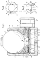
- the tripod head consists essentially of a cylindrical housing 1, a joint ball 2 with a Section 3 for connecting to an optical device, the is rotatably and pivotally mounted in the housing 1, a Bearing 4 for the ball joint 2 and a device 5 for fixing the joint ball 2.
- the Housing is at one end with a plate 10th completed, with a threaded hole 12 for Connect with a tripod is provided. On the other end is the housing 1 with a bearing ring 12 for the Joint ball 2 provided.
- the Joint ball a symmetrical or asymmetrical Rotational body is or a flattened Is rotational ellipsoid, i. has about the shape of a Earth globe, which has a larger one in the area of the equatorial line Diameter has.
- the bearing shell 4 is provided with a at the periphery of Joint ball 2 fitting sliding surface 7 is provided and is axially displaceable and rotatably arranged in the housing 1.
- the bearing shell 4 is on the device 5 for Locking the joint ball supported.
- the bearing shell 4 is made of plastic.
- the device 5 is arranged on a plate 17, the is held by a snap ring 18 in the housing 1.
- the device 5 comprises a support 6, two Sliding parts 19,20 and an adjusting device 25th
- the support 6 is an annular body, which on a Front side a flat bearing surface for the bearing shell. 4 and at the other end two approaches 13,14 having.
- the lugs 13,14 are each other arranged opposite each other and each have one Bevel 15 (Fig.2).
- the two sliding parts 19,20 lie on the one hand on the Plate 17 and on the other hand with a Slanted surface 21 provided.
- the inclined surfaces 15 am Support 6 and on the sliding parts 19,20 have opposite inclinations with the same inclination angle.
- the support 6 and the sliding parts 19,20 are with their Inclined surfaces 15,21 arranged one above the other, so that a radial displacement of the sliding parts 19,20 a displacement of the support 6 in the direction of Joint ball causes.
- This radial displacement is due to the Actuator 25 causes, consisting of a threaded spindle 26 and a knob 27 is.
- a threaded spindle 26 This is in the Sliding parts 19,20 each provided a threaded hole and on the threaded spindle 26 are threaded portions with left-handed or right-handed thread 28,29 formed on which the slide parts 19,20 are screwed on.
- the threaded spindle 26 is one-sided led out of the housing 1 and at this end with provided the knob 27.
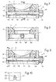
- the Support is an annular body 31, which at one Front side a flat bearing surface for the bearing shell. 4 and on the other end face two grooves 32nd has, which are arranged diametrically opposite one another.
- the device 5 for fixing the joint ball has two cams 35 with an identical contour and an adjusting device 36 with a shaft 37 and a Lever 38 on.
- the cams 35 are by means of pins 34 mounted on the shaft 37 and are with the Grooves 32 in the bearing 31 in engagement.
- the shaft 37 is mounted in a bearing ring 39, which in the housing. 1 is arranged.
- the support 41 is an annular body with two levels Faces.
- the device 5 for detecting the joint ball contains an organ 42 consisting of a sleeve 44 with two at a distance mutually formed cam 45 is made and a Actuator 46, which consists of a shaft 47 and a Knob 48 consists.
- the sleeve 44 is by means of two Pins 49 connected to the shaft 47.
- a ring 50 in FIG Housing 1 is arranged.
- Figures 9 and 10 show an embodiment in which the support 61 has an L-shaped cross-section and in the Leg 62 two oppositely formed slots 63, which the shaft 47 of the actuator embrace and thus a rotational movement of the support 61st prevent.
- the organ is cylindrical Body with an offset to the axis of the body Can exist through hole.
Landscapes
- Engineering & Computer Science (AREA)
- General Engineering & Computer Science (AREA)
- Mechanical Engineering (AREA)
- Pivots And Pivotal Connections (AREA)
- Headphones And Earphones (AREA)
- Walking Sticks, Umbrellas, And Fans (AREA)
- Particle Accelerators (AREA)
- Accessories Of Cameras (AREA)
Abstract
Description
- Fig.1
- einen Schnitt durch eine bevorzugte Ausführung eines erfindungsgemässen Stativkopfes,
- Fig.2
- eine in Richtung des Pfeiles II betrachtete Ansicht des Auflagers nach Fig.1,
- Fig.3
- eine in Richtung des Pfeiles III betrachtete Ansicht der Feststelleinrichtung,
- Fig.4
- einen Schnitt durch eine andere Ausführung eines erfindungsgemässen Stativkopfes,
- Fig.5
- eine andere Ausführung einer Feststelleinrichtung,
- Fig.6
- eine Schnitt entlang der Linie VI-VI in Fig.5,
- Fig.7
- eine weitere Ausführung einer Feststelleinrichtung,
- Fig.8
- einen Schnitt entlang der Linie VIII VIII in Fig.7,

- Fig.9
- eine Modifikation der Ausführung nach Fig.7 und
- Fig. 10
- eine Ansicht in Richtung des Pfeiles A in Fig.9.
Claims (11)
- Stativkopf enthaltend ein zylindrisches Gehäuse (1), das an einem Ende ein Anschlussmittel (11) für ein Stativ aufweist, eine Gelenkkugel (2), die drehbar und schwenkbar im Gehäuse (1) gelagert ist, einen Aufnahmeteil (4) für die Gelenkkugel (2) und eine Einrichtung (5) zum Feststellen der Gelenkkugel mit mindestens einem Feststellorgan und mit einer Stellschraube, welche Einrichtung (5) zur Erzielung einer Klemmwirkung die Gelenkkugel (2) gegen das Gehäuse (1) drückt, dadurch gekennzeichnet, dass der Aufnahmeteil ein Lagerelement (4) mit einer am Umfang der Gelenkkugel anliegende Gleitfläche (7) ist, das im Gehäuse axial verschiebbar und drehbar angeordnet ist und dass die Einrichtung (5) zum Feststellen der Gelenkkugel ein Auflager (6;31;41;61) für das Lagerelement (4) und mit dem Auflager (6) in Wirkverbindung stehende Mittel (19,20,25;35,36;42,44) aufweist, um das Lagerelement (6) zur Erzielung der Klemmwirkung gegen die Gelenkkugel verschieben.
- Stativkopf nach Anspruch 1, dadurch gekennzeichnet, dass das Lagerelement (4) eine Schale ist.
- Stativkopf nach Anspruch 1, dadurch gekennzeichnet, dass ein Wälzlager (30) zwischen dem Lagerelement (4) und dem Auflager (6) vorgesehen ist.
- Stativkopf nach Anspruch 1, dadurch gekennzeichnet, dass die Einrichtung (5) zum Feststellen der Gelenkkugel ein Auflager (6) mit zwei Ansätzen, die mit einer Schrägfläche versehen sind, zwei jeweils mit einer Schrägfläche versehene Organe (19,20), die auf einer ortsfesten Unterlage (17) abgestützt, mit ihren Schrägflächen an den Schrägflächen der Ansätze des Auflagers (6) anliegend und quer zueinander verschiebbar angeordnet sind und eine Stelleinrichtung (25) mit einem Stellorgan (26), das mit den Organen (19,20) in Eingriff ist und mit einem Betätigungselement (27) aufweist, um durch eine Drehbewegung die Organe (19,20) zu den Ansätzen am Auflager (6) quer zu verschieben und das Lagerelement (4) zur Erzielung der Klemmwirkung gegen die Gelenkkugel (1) zu verschieben.
- Stativkopf nach Anspruch 1, dadurch gekennzeichnet, dass die Einrichtung (5) zum Feststellen der Gelenkkugel ein Auflager(31), das als ringförmiger Körper mit ebenen Stirnflächen ausgebildet ist, mindestens ein Organ (35) mit einer exzentrischen Kontur, das mit dem Auflager (6) im Eingriff steht, und eine Stelleinrichtung (36) mit einem Stellorgan (37), das mit dem Organ (35) verbunden ist und mit einem Betätigungselement (38) enthält, das mit dem Stellorgan (37) verbunden ist, um durch eine Drehoder Schwenkbewegung das Lagerelement (4) gegen die Gelenkkugel (1) zu verschieben.
- Stativkopf nach Anspruch 5, dadurch gekennzeichnet, dass das Auflager (31) mindestens eine mit dem exzentrischen Organ (35) in Eingriff stehende Auskehlung (32) aufweist, um eine axiale Drehbewegung des Auflagers (31) zu verhindern.
- Stativkopf nach Anspruch 5, dadurch gekennzeichnet, dass das Auflager (61) einen L- förmigen Querschnitt aufweist und dass das Auflager (61) mit dem Stellorgan (47) in Eingriff ist, um eine axiale Drehbewegung des Auflagers (61) zu verhindern.
- Stativkopf nach Anspruch 4 oder 5, dadurch gekennzeichnet, dass das Betätigungselement ein Drehknopf (48) oder ein Hebel (38) ist.
- Stativkopf nach Anspruch 1, dadurch gekennzeichnet, dass die Gelenkkugel (2) ein asymmetrischer Rotationskörper ist. Statvkopf nach Anspruch 1, dadurch gekennzeichnet, dass die Gelenkkugel (2) eine Kontur hat, derart, dass das abhängig von der Schwenkbewegung der Gelenkkugel (2) die Klemmwirkung zu- bzw. abnimmt.
- Stativkopf nach Anspruch 1, dadurch gekennzeichnet, dass die Gelenkkugel (2) ein symmetrischer Rotationskörper ist.
- Stativkopf nach Anspruch 1, dadurch gekennzeichnet, dass die Gelenkkugel (2) ein asymmetrischer Rotationskörper ist.
Priority Applications (6)
| Application Number | Priority Date | Filing Date | Title |
|---|---|---|---|
| EP03405307A EP1473510B1 (de) | 2003-05-01 | 2003-05-01 | Stativkopf |
| AT03405307T ATE449931T1 (de) | 2003-05-01 | 2003-05-01 | Stativkopf |
| DE50312154T DE50312154D1 (de) | 2003-05-01 | 2003-05-01 | Stativkopf |
| CNB2004100766093A CN1325834C (zh) | 2003-05-01 | 2004-05-01 | 三角架头 |
| US10/838,127 US7300028B2 (en) | 2003-05-01 | 2004-05-03 | Tripod head |
| HK05106037.7A HK1073352B (en) | 2003-05-01 | 2005-07-15 | Tripod head |
Applications Claiming Priority (1)
| Application Number | Priority Date | Filing Date | Title |
|---|---|---|---|
| EP03405307A EP1473510B1 (de) | 2003-05-01 | 2003-05-01 | Stativkopf |
Publications (2)
| Publication Number | Publication Date |
|---|---|
| EP1473510A1 true EP1473510A1 (de) | 2004-11-03 |
| EP1473510B1 EP1473510B1 (de) | 2009-11-25 |
Family
ID=32982019
Family Applications (1)
| Application Number | Title | Priority Date | Filing Date |
|---|---|---|---|
| EP03405307A Expired - Lifetime EP1473510B1 (de) | 2003-05-01 | 2003-05-01 | Stativkopf |
Country Status (5)
| Country | Link |
|---|---|
| US (1) | US7300028B2 (de) |
| EP (1) | EP1473510B1 (de) |
| CN (1) | CN1325834C (de) |
| AT (1) | ATE449931T1 (de) |
| DE (1) | DE50312154D1 (de) |
Cited By (8)
| Publication number | Priority date | Publication date | Assignee | Title |
|---|---|---|---|---|
| WO2009056249A1 (de) | 2007-10-30 | 2009-05-07 | Flm Gmbh | Stativkopf |
| EP2063138A1 (de) * | 2007-11-23 | 2009-05-27 | Zirkona Sweden AB | Kugelgelenkvorrichtung |
| DE102010024657A1 (de) | 2010-06-22 | 2011-12-22 | FLM GMBH FOTO-, LICHT- UND MEßTECHNISCHES ZUBEHÖR | Stativkopf |
| DE102012101007A1 (de) | 2012-02-08 | 2013-08-08 | Philippe Vogt | Stativkopf |
| NL1039848A (en) * | 2012-10-11 | 2014-04-14 | Bandit N V | Adjustable connector for fog-generating device. |
| WO2014195745A1 (en) * | 2013-06-07 | 2014-12-11 | Karai Csaba | Head assembly for supporting and adjusting the position of an optical or electronic device |
| USD847696S1 (en) | 2017-02-02 | 2019-05-07 | Aircraft Gear Corporation | Tie rod connector |
| EP4102126A4 (de) * | 2021-03-25 | 2024-03-27 | Zhongshan Dashan Photographic Equipment Co., Ltd. | Ständer für eine fotografievorrichtung |
Families Citing this family (38)
| Publication number | Priority date | Publication date | Assignee | Title |
|---|---|---|---|---|
| AT6961U3 (de) * | 2003-12-22 | 2005-03-25 | Harald Burgstaller | Verstell- und fixiervorrichtung |
| US7581266B2 (en) * | 2004-12-03 | 2009-09-01 | Stryker Corporation | Calf support assembly for a maternity bed foot support and abduction assembly |
| US20070153459A1 (en) * | 2006-01-04 | 2007-07-05 | Jim Wohlford | Mounting system for flat panel electronic display |
| US20070152116A1 (en) * | 2006-01-05 | 2007-07-05 | Larry Shawn Madsen | Ball head |
| US7644500B2 (en) * | 2006-01-17 | 2010-01-12 | Federal-Mogul World Wide, Inc. | Method of setting the pre-load for a ball socket joint |
| US8052104B2 (en) | 2006-12-13 | 2011-11-08 | Intuitive Corporation | Mounting head |
| JP2010540848A (ja) * | 2007-09-21 | 2010-12-24 | ディーア・アンド・カンパニー | 作業車両用の玉継手 |
| US8267361B1 (en) | 2007-10-18 | 2012-09-18 | Acratech, Inc. | Attachment to a long lens support device which functions as both a ball head and a gimble head |
| JP5426934B2 (ja) * | 2009-06-11 | 2014-02-26 | 株式会社東信製作所 | 球体のロック装置 |
| US8894316B2 (en) * | 2009-07-22 | 2014-11-25 | Music Express, Llc | Adjustable joint for microphone |
| CA2716310A1 (en) * | 2009-10-19 | 2011-04-19 | Denis Joanisse | An adjustable support |
| US8753032B2 (en) * | 2009-10-28 | 2014-06-17 | Honda Motor Co., Ltd. | Friction controlled ball joint |
| US8474575B2 (en) * | 2010-08-04 | 2013-07-02 | Latchways Plc | Mounting for a safety system |
| CN202120021U (zh) * | 2011-03-14 | 2012-01-18 | 中山市思锐摄影器材工业有限公司 | 摄影云台锁紧装置 |
| CN202120022U (zh) * | 2011-03-14 | 2012-01-18 | 中山市思锐摄影器材工业有限公司 | 一种摄影云台锁紧装置 |
| US9109616B1 (en) | 2011-06-24 | 2015-08-18 | Manic Nomad Llc | Clamp |
| US8702339B2 (en) * | 2011-06-24 | 2014-04-22 | Manic Nomad, LLC | Clamp |
| EP2761220B1 (de) * | 2011-09-26 | 2018-12-26 | Access Products Group LLC | Verstellbarer anschluss für mikrofon |
| WO2013048361A1 (en) * | 2011-09-26 | 2013-04-04 | Access Products Group LLC | Adjustable joint for microphone |
| WO2013066223A1 (en) * | 2011-11-02 | 2013-05-10 | Husqvarna Ab | Handle height adjustment device of walk-behind power tool, a handle assembly and a walk-behind power tool comprising such a device |
| US8910914B2 (en) * | 2012-04-04 | 2014-12-16 | Audix Corporation | Mount for electronics equipment |
| CN102900925B (zh) * | 2012-09-19 | 2015-04-08 | 苏州佳世达电通有限公司 | 电子设备及其支撑装置 |
| US9232966B2 (en) * | 2012-09-24 | 2016-01-12 | Refai Technologies, Llc | Articulating spinal rod system |
| CN103307420B (zh) * | 2013-06-28 | 2016-05-18 | 中山市思锐摄影器材工业有限公司 | 一种适用于独脚架的球头定向装置 |
| US10030694B2 (en) | 2013-12-17 | 2018-07-24 | Ingersoll-Rand Company | Adjustable joints |
| CN105511041A (zh) * | 2016-01-18 | 2016-04-20 | 苏州艾力光电科技有限公司 | 一种光学元件可调固定装置 |
| EP3246615B1 (de) | 2016-05-20 | 2018-05-02 | Axis AB | Montagevorrichtung |
| US10419649B2 (en) * | 2016-10-17 | 2019-09-17 | Arlo Technologies, Inc. | Electronic device mount |
| USD847036S1 (en) | 2017-02-02 | 2019-04-30 | Aircraft Gear Corporation | Tie rod end |
| CA3016889A1 (en) * | 2017-09-08 | 2019-03-08 | Aaron Fenster | A counterbalancing mechanism and stabilizer design and method for counterbalancing and stabilizing a load |
| DE102019109259B4 (de) * | 2019-04-09 | 2021-03-25 | AFS Fördertechnik GmbH | Ausrichtevorrichtung für ein Vermessungsgerät |
| US11248737B2 (en) | 2019-08-12 | 2022-02-15 | Trent Ballentine | Clamps |
| US11339916B2 (en) | 2019-10-25 | 2022-05-24 | Cade Smith | Tripod |
| WO2022046883A1 (en) * | 2020-08-25 | 2022-03-03 | Axon Enterprise, Inc. | Spherical joint with leveling and panning capability |
| WO2023282690A1 (ko) * | 2021-07-08 | 2023-01-12 | 한화테크윈 주식회사 | 전자기기 장착 어셈블리 |
| CN117346032A (zh) * | 2023-11-09 | 2024-01-05 | 梁小映 | 一种磁吸球形云台及三脚架云台组件 |
| CN119282244B (zh) * | 2024-12-11 | 2025-05-27 | 希达空调净化设备有限公司 | 一种空调干燥器加工用切割装置 |
| CN119554531B (zh) * | 2025-02-05 | 2025-04-22 | 四川省商投信息技术有限责任公司 | 一种多向led显示屏支撑收纳装置 |
Citations (7)
| Publication number | Priority date | Publication date | Assignee | Title |
|---|---|---|---|---|
| DE612723C (de) | 1935-05-03 | Paul Kuepfer | Stativ, Klammerstativ o. dgl. | |
| FR1018869A (fr) * | 1950-04-06 | 1953-01-14 | Dispositif à rotule pour la fixation à son pied-support d'un appareil de prise de vues | |
| US3211405A (en) * | 1964-01-30 | 1965-10-12 | Fey | Support for photographic instruments and the like |
| DE2203196A1 (de) | 1972-01-24 | 1973-08-02 | Kuerbi & Niggeloh | Tischstativ |
| EP0349948A1 (de) | 1988-07-06 | 1990-01-10 | Philippe Vogt | Stativkopf |
| EP0984219A1 (de) * | 1998-08-29 | 2000-03-08 | FLM GmbH Foto-, Licht- und Messtechnisches Zubehör | Stativkopf |
| FR2799807A1 (fr) | 1999-10-14 | 2001-04-20 | Gitzo Holding | Dispositif de verrouillage d'une rotule |
Family Cites Families (6)
| Publication number | Priority date | Publication date | Assignee | Title |
|---|---|---|---|---|
| FR2346594A1 (fr) | 1976-04-01 | 1977-10-28 | Pflieger Roger | Dispositif de blocage d'une articulation a rotule |
| US4974802A (en) * | 1989-06-19 | 1990-12-04 | Hava Nice Life, Inc. | Adjustable swivel |
| US5590870A (en) * | 1995-06-02 | 1997-01-07 | Advanced Machine & Engineering Co. | Universal holding system for a contoured workpiece |
| DE19604001C2 (de) * | 1996-02-05 | 1998-07-16 | Leica Instr Gmbh | Einrichtung zur Orientierung eines gekühlten Objektkopfes in einem Kryostat-Mikrotom |
| US5806821A (en) * | 1996-03-28 | 1998-09-15 | Matthews Studio Equipment, Inc. | Positionable support head |
| ITPD980096A1 (it) * | 1998-04-23 | 1999-10-23 | Manfrotto Lino & C Spa | Treppiede perfezionato, particolarmente per usi fotografici |
-
2003
- 2003-05-01 AT AT03405307T patent/ATE449931T1/de not_active IP Right Cessation
- 2003-05-01 EP EP03405307A patent/EP1473510B1/de not_active Expired - Lifetime
- 2003-05-01 DE DE50312154T patent/DE50312154D1/de not_active Expired - Lifetime
-
2004
- 2004-05-01 CN CNB2004100766093A patent/CN1325834C/zh not_active Expired - Lifetime
- 2004-05-03 US US10/838,127 patent/US7300028B2/en not_active Expired - Lifetime
Patent Citations (7)
| Publication number | Priority date | Publication date | Assignee | Title |
|---|---|---|---|---|
| DE612723C (de) | 1935-05-03 | Paul Kuepfer | Stativ, Klammerstativ o. dgl. | |
| FR1018869A (fr) * | 1950-04-06 | 1953-01-14 | Dispositif à rotule pour la fixation à son pied-support d'un appareil de prise de vues | |
| US3211405A (en) * | 1964-01-30 | 1965-10-12 | Fey | Support for photographic instruments and the like |
| DE2203196A1 (de) | 1972-01-24 | 1973-08-02 | Kuerbi & Niggeloh | Tischstativ |
| EP0349948A1 (de) | 1988-07-06 | 1990-01-10 | Philippe Vogt | Stativkopf |
| EP0984219A1 (de) * | 1998-08-29 | 2000-03-08 | FLM GmbH Foto-, Licht- und Messtechnisches Zubehör | Stativkopf |
| FR2799807A1 (fr) | 1999-10-14 | 2001-04-20 | Gitzo Holding | Dispositif de verrouillage d'une rotule |
Cited By (19)
| Publication number | Priority date | Publication date | Assignee | Title |
|---|---|---|---|---|
| WO2009056249A1 (de) | 2007-10-30 | 2009-05-07 | Flm Gmbh | Stativkopf |
| DE102007052039B3 (de) * | 2007-10-30 | 2009-06-10 | FLM GMBH FOTO-, LICHT- UND MEßTECHNISCHES ZUBEHÖR | Stativkopf |
| EP2273178A1 (de) | 2007-10-30 | 2011-01-12 | FLM GmbH Foto-, Licht- und Messtechnisches Zubehör | Stativkopf |
| US8282055B2 (en) | 2007-10-30 | 2012-10-09 | Flm Gmbh Foto-, Licht- Und Messtechnisches Zubehoer | Tripod head |
| EP2063138A1 (de) * | 2007-11-23 | 2009-05-27 | Zirkona Sweden AB | Kugelgelenkvorrichtung |
| WO2009065933A3 (en) * | 2007-11-23 | 2009-07-30 | Zirkona Sweden Ab | A ball joint device |
| US7993069B2 (en) | 2007-11-23 | 2011-08-09 | Zirkona Sweden Ab | Ball joint device |
| WO2011160805A3 (de) * | 2010-06-22 | 2012-05-24 | FLM GMBH FOTO-, LICHT- UND MEßTECHNISCHES ZUBEHÖR | Stativkopf |
| WO2011160805A2 (de) | 2010-06-22 | 2011-12-29 | FLM GMBH FOTO-, LICHT- UND MEßTECHNISCHES ZUBEHÖR | Stativkopf |
| DE102010024657A1 (de) | 2010-06-22 | 2011-12-22 | FLM GMBH FOTO-, LICHT- UND MEßTECHNISCHES ZUBEHÖR | Stativkopf |
| DE102012101007A1 (de) | 2012-02-08 | 2013-08-08 | Philippe Vogt | Stativkopf |
| WO2013117538A1 (de) | 2012-02-08 | 2013-08-15 | Philippe Vogt | Stativkopf |
| NL1039848A (en) * | 2012-10-11 | 2014-04-14 | Bandit N V | Adjustable connector for fog-generating device. |
| BE1021439B1 (nl) * | 2012-10-11 | 2015-11-20 | Bandit N.V. | Verstelbare connector voor nevelgenererend apparaat |
| WO2014195745A1 (en) * | 2013-06-07 | 2014-12-11 | Karai Csaba | Head assembly for supporting and adjusting the position of an optical or electronic device |
| EA030425B1 (ru) * | 2013-06-07 | 2018-08-31 | Чаба Караи | Головка для регулировки и сохранения положения оптического или электронного устройства |
| USD847696S1 (en) | 2017-02-02 | 2019-05-07 | Aircraft Gear Corporation | Tie rod connector |
| USD891999S1 (en) | 2017-02-02 | 2020-08-04 | Aircraft Gear Corporation | Tie rod connector |
| EP4102126A4 (de) * | 2021-03-25 | 2024-03-27 | Zhongshan Dashan Photographic Equipment Co., Ltd. | Ständer für eine fotografievorrichtung |
Also Published As
| Publication number | Publication date |
|---|---|
| DE50312154D1 (de) | 2010-01-07 |
| CN1573202A (zh) | 2005-02-02 |
| EP1473510B1 (de) | 2009-11-25 |
| US20050001116A1 (en) | 2005-01-06 |
| CN1325834C (zh) | 2007-07-11 |
| ATE449931T1 (de) | 2009-12-15 |
| US7300028B2 (en) | 2007-11-27 |
| HK1073352A1 (en) | 2005-09-30 |
Similar Documents
| Publication | Publication Date | Title |
|---|---|---|
| EP1473510A1 (de) | Stativkopf | |
| EP0349948B1 (de) | Stativkopf | |
| DE19521710B4 (de) | Panoramakopf für optische Geräte, insbesondere für Fotoapparate | |
| EP2812622B1 (de) | Stativkopf | |
| DE102010017707B4 (de) | Manueller Fokussiermechanismus eines Abbildungsgeräts und Abbildungsgerät | |
| EP1788299B1 (de) | Halterung für ein optisches Gerät | |
| DE2419495A1 (de) | Regelvorrichtung fuer hydraulische maschinen | |
| EP0258646B1 (de) | Stativ für optische Geräte | |
| DE102005038237A1 (de) | Mechanismus zur montageseitigen Schärfeneinstellung eines Varioobjektivs | |
| DE202008016454U1 (de) | Werkzeug zum Polieren und Feinschleifen von optisch wirksamen Flächen in der Feinoptik | |
| DE102017100652B4 (de) | Umkehrsystem für Zielfernrohre und Zielfernrohr mit einem solchen | |
| DE10118216A1 (de) | Ruderblatt-Lagereinrichtung für ein Geschoß | |
| AT398641B (de) | Binokulares fernrohr | |
| AT521537A2 (de) | Gefaltete relaisfeder für ein optisches visier | |
| EP1053496B1 (de) | Zylindrische fassung für verstellbare optische bauelemente | |
| EP1548483A1 (de) | Mikroskopobjektiv mit axial verstellbaren Korrekturfassungen | |
| DE2601308C3 (de) | Fernverstellbarer Außenrückblickspiegel für Fahrzeuge, insbesondere Kraftfahrzeuge | |
| DE102017121229B4 (de) | Armlehne | |
| EP0525507A2 (de) | Vorrichtung zum Verstellen des Stellgliedes für die Verdrängungsvolumenänderung einer hydrostatischen Maschine | |
| DE3912493C2 (de) | ||
| DE10015186B4 (de) | Objektivfassung | |
| DE102013213254A1 (de) | Betätigungseinheit für ein optisches element mit zweidimensionalem stellantrieb | |
| EP3917804B1 (de) | Sichteinstellmechanismus | |
| EP2365274A2 (de) | Zielfernrohr mit einer Umkehrsystem-Lagerung | |
| DE10318196A1 (de) | Sperrvorrichtung für einen Betätigungsring eines Fernsehkameraobjektivs |
Legal Events
| Date | Code | Title | Description |
|---|---|---|---|
| PUAI | Public reference made under article 153(3) epc to a published international application that has entered the european phase |
Free format text: ORIGINAL CODE: 0009012 |
|
| 17P | Request for examination filed |
Effective date: 20040216 |
|
| AK | Designated contracting states |
Kind code of ref document: A1 Designated state(s): AT BE BG CH CY CZ DE DK EE ES FI FR GB GR HU IE IT LI LU MC NL PT RO SE SI SK TR |
|
| AX | Request for extension of the european patent |
Extension state: AL LT LV MK |
|
| 17Q | First examination report despatched |
Effective date: 20041026 |
|
| AKX | Designation fees paid |
Designated state(s): AT BE BG CH CY CZ DE DK EE ES FI FR GB GR HU IE IT LI LU MC NL PT RO SE SI SK TR |
|
| RAP1 | Party data changed (applicant data changed or rights of an application transferred) |
Owner name: VOGT, PHILIPPE |
|
| RIN1 | Information on inventor provided before grant (corrected) |
Inventor name: VOGT, PHILIPPE |
|
| GRAP | Despatch of communication of intention to grant a patent |
Free format text: ORIGINAL CODE: EPIDOSNIGR1 |
|
| GRAJ | Information related to disapproval of communication of intention to grant by the applicant or resumption of examination proceedings by the epo deleted |
Free format text: ORIGINAL CODE: EPIDOSDIGR1 |
|
| GRAP | Despatch of communication of intention to grant a patent |
Free format text: ORIGINAL CODE: EPIDOSNIGR1 |
|
| GRAS | Grant fee paid |
Free format text: ORIGINAL CODE: EPIDOSNIGR3 |
|
| GRAA | (expected) grant |
Free format text: ORIGINAL CODE: 0009210 |
|
| AK | Designated contracting states |
Kind code of ref document: B1 Designated state(s): AT BE BG CH CY CZ DE DK EE ES FI FR GB GR HU IE IT LI LU MC NL PT RO SE SI SK TR |
|
| REG | Reference to a national code |
Ref country code: GB Ref legal event code: FG4D Free format text: NOT ENGLISH |
|
| REG | Reference to a national code |
Ref country code: CH Ref legal event code: EP |
|
| REG | Reference to a national code |
Ref country code: IE Ref legal event code: FG4D |
|
| REF | Corresponds to: |
Ref document number: 50312154 Country of ref document: DE Date of ref document: 20100107 Kind code of ref document: P |
|
| REG | Reference to a national code |
Ref country code: NL Ref legal event code: VDEP Effective date: 20091125 |
|
| PG25 | Lapsed in a contracting state [announced via postgrant information from national office to epo] |
Ref country code: FI Free format text: LAPSE BECAUSE OF FAILURE TO SUBMIT A TRANSLATION OF THE DESCRIPTION OR TO PAY THE FEE WITHIN THE PRESCRIBED TIME-LIMIT Effective date: 20091125 Ref country code: SE Free format text: LAPSE BECAUSE OF FAILURE TO SUBMIT A TRANSLATION OF THE DESCRIPTION OR TO PAY THE FEE WITHIN THE PRESCRIBED TIME-LIMIT Effective date: 20091125 Ref country code: PT Free format text: LAPSE BECAUSE OF FAILURE TO SUBMIT A TRANSLATION OF THE DESCRIPTION OR TO PAY THE FEE WITHIN THE PRESCRIBED TIME-LIMIT Effective date: 20100325 |
|
| PG25 | Lapsed in a contracting state [announced via postgrant information from national office to epo] |
Ref country code: SI Free format text: LAPSE BECAUSE OF FAILURE TO SUBMIT A TRANSLATION OF THE DESCRIPTION OR TO PAY THE FEE WITHIN THE PRESCRIBED TIME-LIMIT Effective date: 20091125 Ref country code: CY Free format text: LAPSE BECAUSE OF FAILURE TO SUBMIT A TRANSLATION OF THE DESCRIPTION OR TO PAY THE FEE WITHIN THE PRESCRIBED TIME-LIMIT Effective date: 20091125 |
|
| REG | Reference to a national code |
Ref country code: IE Ref legal event code: FD4D |
|
| PG25 | Lapsed in a contracting state [announced via postgrant information from national office to epo] |
Ref country code: ES Free format text: LAPSE BECAUSE OF FAILURE TO SUBMIT A TRANSLATION OF THE DESCRIPTION OR TO PAY THE FEE WITHIN THE PRESCRIBED TIME-LIMIT Effective date: 20100308 Ref country code: NL Free format text: LAPSE BECAUSE OF FAILURE TO SUBMIT A TRANSLATION OF THE DESCRIPTION OR TO PAY THE FEE WITHIN THE PRESCRIBED TIME-LIMIT Effective date: 20091125 Ref country code: RO Free format text: LAPSE BECAUSE OF FAILURE TO SUBMIT A TRANSLATION OF THE DESCRIPTION OR TO PAY THE FEE WITHIN THE PRESCRIBED TIME-LIMIT Effective date: 20091125 Ref country code: DK Free format text: LAPSE BECAUSE OF FAILURE TO SUBMIT A TRANSLATION OF THE DESCRIPTION OR TO PAY THE FEE WITHIN THE PRESCRIBED TIME-LIMIT Effective date: 20091125 Ref country code: BG Free format text: LAPSE BECAUSE OF FAILURE TO SUBMIT A TRANSLATION OF THE DESCRIPTION OR TO PAY THE FEE WITHIN THE PRESCRIBED TIME-LIMIT Effective date: 20100225 Ref country code: EE Free format text: LAPSE BECAUSE OF FAILURE TO SUBMIT A TRANSLATION OF THE DESCRIPTION OR TO PAY THE FEE WITHIN THE PRESCRIBED TIME-LIMIT Effective date: 20091125 Ref country code: IE Free format text: LAPSE BECAUSE OF FAILURE TO SUBMIT A TRANSLATION OF THE DESCRIPTION OR TO PAY THE FEE WITHIN THE PRESCRIBED TIME-LIMIT Effective date: 20091125 |
|
| PG25 | Lapsed in a contracting state [announced via postgrant information from national office to epo] |
Ref country code: SK Free format text: LAPSE BECAUSE OF FAILURE TO SUBMIT A TRANSLATION OF THE DESCRIPTION OR TO PAY THE FEE WITHIN THE PRESCRIBED TIME-LIMIT Effective date: 20091125 Ref country code: CZ Free format text: LAPSE BECAUSE OF FAILURE TO SUBMIT A TRANSLATION OF THE DESCRIPTION OR TO PAY THE FEE WITHIN THE PRESCRIBED TIME-LIMIT Effective date: 20091125 |
|
| PLBE | No opposition filed within time limit |
Free format text: ORIGINAL CODE: 0009261 |
|
| STAA | Information on the status of an ep patent application or granted ep patent |
Free format text: STATUS: NO OPPOSITION FILED WITHIN TIME LIMIT |
|
| PG25 | Lapsed in a contracting state [announced via postgrant information from national office to epo] |
Ref country code: GR Free format text: LAPSE BECAUSE OF FAILURE TO SUBMIT A TRANSLATION OF THE DESCRIPTION OR TO PAY THE FEE WITHIN THE PRESCRIBED TIME-LIMIT Effective date: 20100226 |
|
| 26N | No opposition filed |
Effective date: 20100826 |
|
| BERE | Be: lapsed |
Owner name: VOGT, PHILIPPE Effective date: 20100531 |
|
| PG25 | Lapsed in a contracting state [announced via postgrant information from national office to epo] |
Ref country code: MC Free format text: LAPSE BECAUSE OF NON-PAYMENT OF DUE FEES Effective date: 20100531 |
|
| PG25 | Lapsed in a contracting state [announced via postgrant information from national office to epo] |
Ref country code: BE Free format text: LAPSE BECAUSE OF NON-PAYMENT OF DUE FEES Effective date: 20100531 |
|
| PG25 | Lapsed in a contracting state [announced via postgrant information from national office to epo] |
Ref country code: AT Free format text: LAPSE BECAUSE OF NON-PAYMENT OF DUE FEES Effective date: 20100501 |
|
| PG25 | Lapsed in a contracting state [announced via postgrant information from national office to epo] |
Ref country code: HU Free format text: LAPSE BECAUSE OF FAILURE TO SUBMIT A TRANSLATION OF THE DESCRIPTION OR TO PAY THE FEE WITHIN THE PRESCRIBED TIME-LIMIT Effective date: 20100526 Ref country code: LU Free format text: LAPSE BECAUSE OF NON-PAYMENT OF DUE FEES Effective date: 20100501 |
|
| PG25 | Lapsed in a contracting state [announced via postgrant information from national office to epo] |
Ref country code: TR Free format text: LAPSE BECAUSE OF FAILURE TO SUBMIT A TRANSLATION OF THE DESCRIPTION OR TO PAY THE FEE WITHIN THE PRESCRIBED TIME-LIMIT Effective date: 20091125 |
|
| REG | Reference to a national code |
Ref country code: CH Ref legal event code: PL |
|
| PG25 | Lapsed in a contracting state [announced via postgrant information from national office to epo] |
Ref country code: LI Free format text: LAPSE BECAUSE OF NON-PAYMENT OF DUE FEES Effective date: 20120531 Ref country code: CH Free format text: LAPSE BECAUSE OF NON-PAYMENT OF DUE FEES Effective date: 20120531 |
|
| REG | Reference to a national code |
Ref country code: CH Ref legal event code: AECN Free format text: DAS PATENT IST AUFGRUND DES WEITERBEHANDLUNGSANTRAGS VOM 19.02.2013 REAKTIVIERT WORDEN. |
|
| PGRI | Patent reinstated in contracting state [announced from national office to epo] |
Ref country code: LI Effective date: 20130220 Ref country code: CH Effective date: 20130220 |
|
| PGFP | Annual fee paid to national office [announced via postgrant information from national office to epo] |
Ref country code: GB Payment date: 20130521 Year of fee payment: 11 |
|
| GBPC | Gb: european patent ceased through non-payment of renewal fee |
Effective date: 20140501 |
|
| PG25 | Lapsed in a contracting state [announced via postgrant information from national office to epo] |
Ref country code: GB Free format text: LAPSE BECAUSE OF NON-PAYMENT OF DUE FEES Effective date: 20140501 |
|
| REG | Reference to a national code |
Ref country code: FR Ref legal event code: PLFP Year of fee payment: 14 |
|
| PGFP | Annual fee paid to national office [announced via postgrant information from national office to epo] |
Ref country code: FR Payment date: 20160520 Year of fee payment: 14 |
|
| REG | Reference to a national code |
Ref country code: FR Ref legal event code: ST Effective date: 20180131 |
|
| PG25 | Lapsed in a contracting state [announced via postgrant information from national office to epo] |
Ref country code: FR Free format text: LAPSE BECAUSE OF NON-PAYMENT OF DUE FEES Effective date: 20170531 |
|
| PGFP | Annual fee paid to national office [announced via postgrant information from national office to epo] |
Ref country code: CH Payment date: 20181009 Year of fee payment: 16 |
|
| PGFP | Annual fee paid to national office [announced via postgrant information from national office to epo] |
Ref country code: DE Payment date: 20190531 Year of fee payment: 17 Ref country code: IT Payment date: 20190527 Year of fee payment: 17 |
|
| REG | Reference to a national code |
Ref country code: CH Ref legal event code: PL |
|
| PG25 | Lapsed in a contracting state [announced via postgrant information from national office to epo] |
Ref country code: CH Free format text: LAPSE BECAUSE OF NON-PAYMENT OF DUE FEES Effective date: 20190531 Ref country code: LI Free format text: LAPSE BECAUSE OF NON-PAYMENT OF DUE FEES Effective date: 20190531 |
|
| REG | Reference to a national code |
Ref country code: DE Ref legal event code: R119 Ref document number: 50312154 Country of ref document: DE |
|
| PG25 | Lapsed in a contracting state [announced via postgrant information from national office to epo] |
Ref country code: DE Free format text: LAPSE BECAUSE OF NON-PAYMENT OF DUE FEES Effective date: 20201201 |
|
| PG25 | Lapsed in a contracting state [announced via postgrant information from national office to epo] |
Ref country code: IT Free format text: LAPSE BECAUSE OF NON-PAYMENT OF DUE FEES Effective date: 20200501 |