EP1471651A2 - Verfahren zur Vergrösserung des störungsfreien Dynamikbereichs von nichtlinearen signalverarbeitenden Komponenten - Google Patents
Verfahren zur Vergrösserung des störungsfreien Dynamikbereichs von nichtlinearen signalverarbeitenden Komponenten Download PDFInfo
- Publication number
- EP1471651A2 EP1471651A2 EP04005741A EP04005741A EP1471651A2 EP 1471651 A2 EP1471651 A2 EP 1471651A2 EP 04005741 A EP04005741 A EP 04005741A EP 04005741 A EP04005741 A EP 04005741A EP 1471651 A2 EP1471651 A2 EP 1471651A2
- Authority
- EP
- European Patent Office
- Prior art keywords
- component
- frequency
- linear
- output
- calculated
- Prior art date
- Legal status (The legal status is an assumption and is not a legal conclusion. Google has not performed a legal analysis and makes no representation as to the accuracy of the status listed.)
- Ceased
Links
- 238000000034 method Methods 0.000 title claims description 17
- 230000001174 ascending effect Effects 0.000 claims 1
- 238000006243 chemical reaction Methods 0.000 abstract 1
- 230000006870 function Effects 0.000 description 3
- 230000001419 dependent effect Effects 0.000 description 2
- 230000002411 adverse Effects 0.000 description 1
- 230000005540 biological transmission Effects 0.000 description 1
- 238000013016 damping Methods 0.000 description 1
- 238000010586 diagram Methods 0.000 description 1
- 230000000694 effects Effects 0.000 description 1
- 230000001629 suppression Effects 0.000 description 1
Images
Classifications
-
- H—ELECTRICITY
- H04—ELECTRIC COMMUNICATION TECHNIQUE
- H04B—TRANSMISSION
- H04B1/00—Details of transmission systems, not covered by a single one of groups H04B3/00 - H04B13/00; Details of transmission systems not characterised by the medium used for transmission
- H04B1/06—Receivers
- H04B1/16—Circuits
- H04B1/26—Circuits for superheterodyne receivers
- H04B1/28—Circuits for superheterodyne receivers the receiver comprising at least one semiconductor device having three or more electrodes
-
- H—ELECTRICITY
- H04—ELECTRIC COMMUNICATION TECHNIQUE
- H04B—TRANSMISSION
- H04B1/00—Details of transmission systems, not covered by a single one of groups H04B3/00 - H04B13/00; Details of transmission systems not characterised by the medium used for transmission
- H04B1/06—Receivers
- H04B1/10—Means associated with receiver for limiting or suppressing noise or interference
- H04B1/1027—Means associated with receiver for limiting or suppressing noise or interference assessing signal quality or detecting noise/interference for the received signal
- H04B1/1036—Means associated with receiver for limiting or suppressing noise or interference assessing signal quality or detecting noise/interference for the received signal with automatic suppression of narrow band noise or interference, e.g. by using tuneable notch filters
Definitions
- the invention relates to a method for increasing the interference-free dynamic range of signal processing non-linear components.
- spurs When processing received signals from e.g. Generate radar systems nonlinear components, e.g. Amplifiers, mixers or A / D converters, in receiver systems unwanted signals, so-called spurs. Appropriately chosen intermediate or Oscillator frequencies only insufficiently prevent the generation of these artificial ones Signals (spurs).
- the object of the invention is to provide a method with which it is possible to Enlargement of the interference-free dynamic range in signal processing remove artificially generated signals (spurs).
- At least one linear combination of at least one input frequency f in, t, f in, b and fixedly predetermined oscillator frequencies f LOn of the components is calculated from the output signal of the component , which is compared with any output frequency f out, t of the component, the output frequency f out, s then being recognized as a trace and eliminated from the output signal of the component if the calculated linear combination within a predeterminable frequency and power range of any output frequency f out, t corresponds to the component.
- the linear combinations can advantageously be linear combinations of mixer harmonics.
- the linear combinations can also be linear combinations of intermodulations.
- the method according to the invention can also be operated with both types of combination.
- the output frequency f out, s, f out1, s, f outs, 2 of a component can first be examined for agreement with a linear combination of mixer harmonics and then for agreement with a linear combination of intermodulations or vice versa.
- the output frequency f out, s, f out1, s, f outs, 2 is in particular any output frequency of the component.
- the method according to the invention is expediently carried out for each output frequency f out, s, f out1, s , f outs, 2 .
- Mixer combinations arise, for example, when converting a signal in a mixer.
- 1.
- Other parameter values usually lead to damped output signals.
- the power loss ⁇ P caused by the damping can be calculated and is in particular dependent on the power of the mixer oscillator, the input power of the input signal and the parameters A and B. Given the power of the mixer oscillator and the power of the input signal, the power loss ⁇ P can be determined as a function of parameters A and B.
- any output frequency f out, s is selected from the output signal and accepted as the cause.
- the output frequency f out, s can advantageously be selected as a function of the associated power, the output frequencies f out, s to be examined first being sorted according to their power.
- the original input frequency f in, b is advantageous before the signal processing in the component according to the general formula calculated.
- f LOn the oscillator frequency of the nth stage of the N-stage component is designated.
- the respective value of the parameters A and B n is, as described above, +1 or -1.
- the value pairs of parameters A, B n can, for example, be permanently stored in a memory.
- the following table shows an example of some value pairs of parameters A, B.
- a next step it is checked whether an output signal f z out, s calculated by means of a linear combination corresponds to an actual output signal f out, t of the component within a predeterminable frequency and power range. If this is the case, then the output frequency f out, s selected from the output signal and accepted as a track is actually a cause (track) and is eliminated from the output signal.
- This check is carried out in particular for all predetermined value pairs A, B n and all actual output frequencies f out, t in the output signal of the component.
- Term 1 shifts the input frequency f in1, s to the Mth stage of the nonlinear component.
- Term 2 is used to shift the input frequency f in2, s to the Mth stage of the nonlinear component.
- Term 3 calculates the intermodulation at the M stage of the nonlinear component. With the last term, the intermodulation product is pushed to the Nth stage (output) of the nonlinear component, where the calculated output signal f out, b is present.
- a next step it is checked whether the output signal f out, b calculated by means of a linear combination corresponds to an actual output signal f out, t of the component within a predeterminable frequency and power range. If this is the case, then the output frequency f out1, s, f out2, s selected from the output signal and accepted as a track is actually a track and is eliminated from the output signal.
- This check is carried out in particular for all predetermined value pairs A, B and all output frequencies f out in the output signal of the component.
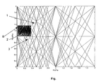
- the parameters A and B can in particular be taken from a track chart diagram (FIG.) Known to a person skilled in the art [1].
- the track chart shows a transmission of an input frequency f in to an output frequency normalized to the oscillator frequency f LO .
- a straight line 1 with slope 1 means the desired transfer from f in to f out .
- the marked area B shows the predeterminable frequency range to be examined.
- the size of the window can be specified depending on the application.
- An advantage of the method according to the invention is that the false alarm rate is clear is reduced. It also increases the recognition performance of actual targets the system not being unnecessary by processing artificially generated signals is charged. Another advantage is that depending on the parameter A and B as well as the frequency and power ranges to be examined is adaptable to any recipient concept.
Landscapes
- Engineering & Computer Science (AREA)
- Computer Networks & Wireless Communication (AREA)
- Signal Processing (AREA)
- Noise Elimination (AREA)
- Amplifiers (AREA)
Abstract
Description
Anschließend wird vorteilhaft die ursprüngliche Eingangsfrequenz fin,b vor der Signalverarbeitung in der Komponente gemäß der allgemeinen Formel

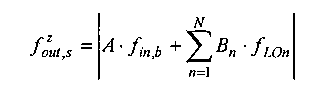
- A, Bn :
- vorgebbare Parameter mit A, Bn ∈ Z,
- fin,b :
- Eingangsfrequenz vor der Komponente
- fLOn :
- Oszillatorfrequenz der n-ten Stufe der nichtlinearen Komponente,
- N :
- Anzahl der Stufen,
- z :
- Laufvariable der berechneten Linearkombinationen
| A | B | ΔP in dB |
| 1 | 1 | 0 |
| 2 | 1 | ΔP-41 |
| 3 | 1 | 2 ΔP-28 |
| 1 | 2 | -35 |
| 2 | 2 | ΔP-39 |
| 3 | 2 | 2 ΔP-44 |
| 1 | 3 | -10 |
| 2 | 3 | ΔP-32 |
mit
- Pin
- Leistung des Eingangssignals,
- PLO
- Leistung der Oszillatorfrequenz fLO nichtlinearen Komponente.
Im nächsten Schritt werden Linearkombinationen für die Ausgangsfrequenz fz out,b berechnet. Hierzu werden für vorgebbare Kombinationen von Parameterpaaren A,B und C mit A,B,C∈Z, wobei der Wertebereich von A, B und C jeweils vorgebbar ist, Linearkombinationen gemäß
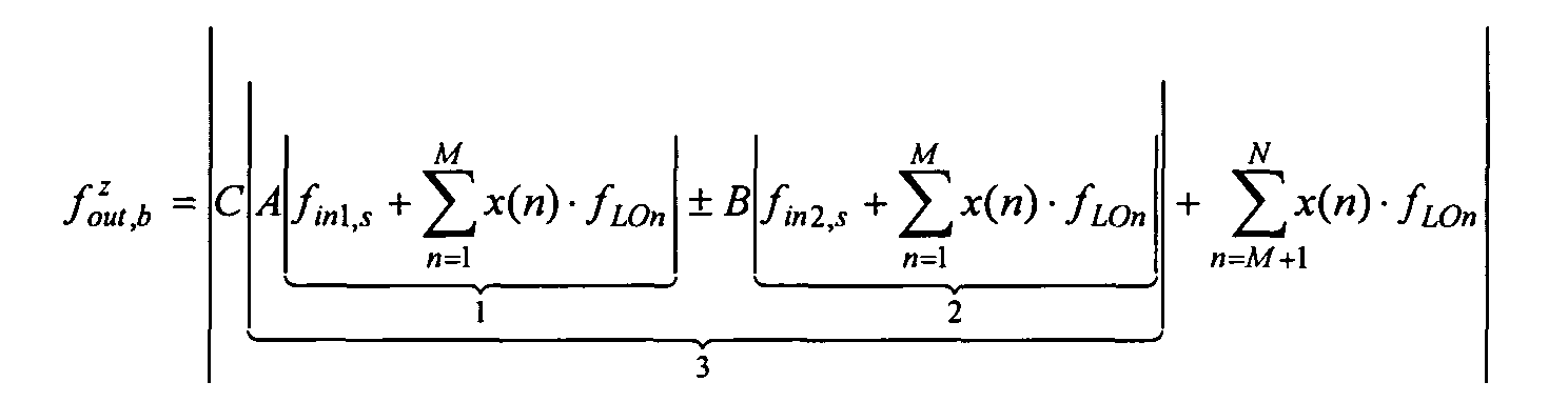
- A, B,C:
- vorgebbare Parameter mit A, B∈Z,
- fin1,s :
- erstes Eingangssignal vor der Komponente,
- fin2,s :
- zweites Eingangssignal vor der Komponente,
- fLOn :
- Oszillatorfrequenz der n-ten Stufe der nichtlinearen Komponente,
- M :
- Anzahl der Stufen der nichtlinearen Komponente,
- N :
- Position der zu untersuchenden nichtlinearen Komponente,
- x(n) :
- vorgebbare Funktion mit Werten +1 und -1,
- z :
- Laufvariable der berechneten Linearkombinationen
Claims (7)
- Verfahren zur Vergrößerung des störungsfreien Dynamikbereichs von nichtlinearen signalverarbeitenden Komponenten in Empfängersystemen bei der Umsetzung von Eingangsfrequenzen fin in Ausgangsfrequenzen fout, dadurch gekennzeichnet, dass für mindestens eine Ausgangsfrequenz fout,s, fout1,s, fouts,2 aus dem Ausgangssignal der Komponente mindestens eine Linearkombination aus mindestens einer Eingangsfrequenz fin,t,fin,b und fest vorgegebener Oszillatorfrequenzen fLOn der Komponenten berechnet wird, welche mit einer beliebigen Ausgangsfrequenz fout,t der Komponente verglichen wird, wobei die Ausgangsfrequenz fout,s, fout1,s, fouts,2 dann als Spur erkannt und aus dem Ausgangssignal der Komponente eliminiert wird, wenn die berechnete Linearkombination innerhalb eines vorgebbaren Frequenz- und Leistungsbereichs einer beliebigen Ausgangsfrequenz fout,t der Komponente entspricht.
- Verfahren nach Anspruch 1, dadurch gekennzeichnet, dass die zu untersuchenden Ausgangsfrequenzen fout,s, fout1,s, fouts,2 im Ausgangssignal nach ihrer Leistung auf- oder absteigend sortiert werden.
- Verfahren nach Anspruch 1 oder 2, dadurch gekennzeichnet, dass die vorgebbare Linearkombination eine Linearkombination von Mischerharmonischen ist.
- Verfahren nach Anspruch 2, dadurch gekennzeichnet, dass für jede zu untersuchende Ausgangsfrequenz fout,s des Ausgangssignals die ursprüngliche Eingangsfrequenz fin,b vor der signalverarbeitenden nichtlinearen Komponente berechnet wird.
- Verfahren nach Anspruch 4, dadurch gekennzeichnet, dass für die Ausgangsfrequenz fout,s Linearkombinationen gemäßmit

- A, Bn:
- vorgebbare Parameter mit A, Bn ∈ Z,
- fin,b :
- Eingangsfrequenz vor der nichtlinearen Komponente
- fLOn :
- Oszillatorfrequenz der n-ten Stufe der nichtlinearen Komponente,
- N :
- Anzahl der Stufen,
- z :
- Laufvariable der berechneten Linearkombinationen
- Verfahren nach Anspruch 2, dadurch gekennzeichnet, dass die vorgebbare Linearkombination eine Linearkombination von Intermodulationen ist.
- Verfahren nach Anspruch 6, dadurch gekennzeichnet, dass die Ausgangsfrequenz fout,b mit einer Linearkombination gemäßmit

- A, B,C :
- vorgebbare Parameter mit A,B∈Z,
- fin1,s :
- erstes Eingangssignal vor der nichtlinearen Komponente,
- fin2,s:
- zweites Eingangssignal vor der nichtlinearen Komponente,
- fLOn :
- Oszillatorfrequenz der n-ten Stufe der nichtlinearen Komponente,
- N :
- Anzahl der Stufen der nichtlinearen Komponente
- M :
- Position der zu untersuchenden nichtlinearen Komponente,
- x(n) :
- vorgebbare Funktion mit Werten +1 und -1,
- z :
- Laufvariable der berechneten Linearkombinationen
Applications Claiming Priority (2)
| Application Number | Priority Date | Filing Date | Title |
|---|---|---|---|
| DE10318754 | 2003-04-25 | ||
| DE10318754A DE10318754B4 (de) | 2003-04-25 | 2003-04-25 | Verfahren zur Vergrößerung des störungsfreien Dynamikbereichs von nichtlinearen signalverarbeitenden Komponenten |
Publications (2)
| Publication Number | Publication Date |
|---|---|
| EP1471651A2 true EP1471651A2 (de) | 2004-10-27 |
| EP1471651A3 EP1471651A3 (de) | 2005-01-05 |
Family
ID=32946430
Family Applications (1)
| Application Number | Title | Priority Date | Filing Date |
|---|---|---|---|
| EP04005741A Ceased EP1471651A3 (de) | 2003-04-25 | 2004-03-11 | Verfahren zur Vergrösserung des störungsfreien Dynamikbereichs von nichtlinearen signalverarbeitenden Komponenten |
Country Status (3)
| Country | Link |
|---|---|
| US (1) | US7218269B2 (de) |
| EP (1) | EP1471651A3 (de) |
| DE (1) | DE10318754B4 (de) |
Cited By (1)
| Publication number | Priority date | Publication date | Assignee | Title |
|---|---|---|---|---|
| US7218269B2 (en) * | 2003-04-25 | 2007-05-15 | Eads Deutschland Gmbh | Method for enlarging the interference-free dynamic range of non-linear signal processing components |
Families Citing this family (2)
| Publication number | Priority date | Publication date | Assignee | Title |
|---|---|---|---|---|
| RU2291462C2 (ru) * | 2004-11-26 | 2007-01-10 | Сергей Юрьевич Акимкин | Система обнаружения и распознавания объектов, включающих элементы с нелинейными вольт-амперными характеристиками |
| US8390527B2 (en) * | 2009-10-21 | 2013-03-05 | Winegard Company | Portable satellite dish antenna system |
Family Cites Families (6)
| Publication number | Priority date | Publication date | Assignee | Title |
|---|---|---|---|---|
| US4885587A (en) * | 1988-12-22 | 1989-12-05 | Westinghouse Electric Corp. | Multibit decorrelated spur digital radio frequency memory |
| US5467091A (en) * | 1994-07-21 | 1995-11-14 | Westinghouse Electric Corp. | Radar and other communication systems having large bandwidth and large dynamic range |
| US5631655A (en) * | 1995-12-21 | 1997-05-20 | Hughes Electronics | System and method for radar receiver harmonic distortion and spurious response control |
| IL132802A (en) * | 1999-11-08 | 2004-03-28 | Rafael Armament Dev Authority | Homidine shelter is free of simulated frequencies |
| GB2372174B (en) * | 2001-02-12 | 2003-07-16 | Matsushita Electric Industrial Co Ltd | Intermediate frequency planning in radio transmitters and receivers |
| DE10318754B4 (de) * | 2003-04-25 | 2008-06-19 | Eads Deutschland Gmbh | Verfahren zur Vergrößerung des störungsfreien Dynamikbereichs von nichtlinearen signalverarbeitenden Komponenten |
-
2003
- 2003-04-25 DE DE10318754A patent/DE10318754B4/de not_active Expired - Fee Related
-
2004
- 2004-03-11 EP EP04005741A patent/EP1471651A3/de not_active Ceased
- 2004-04-23 US US10/830,776 patent/US7218269B2/en not_active Expired - Fee Related
Non-Patent Citations (1)
| Title |
|---|
| None * |
Cited By (1)
| Publication number | Priority date | Publication date | Assignee | Title |
|---|---|---|---|---|
| US7218269B2 (en) * | 2003-04-25 | 2007-05-15 | Eads Deutschland Gmbh | Method for enlarging the interference-free dynamic range of non-linear signal processing components |
Also Published As
| Publication number | Publication date |
|---|---|
| EP1471651A3 (de) | 2005-01-05 |
| US20040263384A1 (en) | 2004-12-30 |
| US7218269B2 (en) | 2007-05-15 |
| DE10318754A1 (de) | 2004-11-25 |
| DE10318754B4 (de) | 2008-06-19 |
Similar Documents
| Publication | Publication Date | Title |
|---|---|---|
| DE3689763T2 (de) | Pulsstörungsdetektion für ein Radarsystem. | |
| DE3689033T2 (de) | Radarsystem mit Verstärkungsregelung. | |
| EP2926152B1 (de) | Verfahren zum orten von fehlerhaften stellen in einem hf-signalübertragungspfad | |
| DE60214271T2 (de) | Mehrstufiger Frequenzumsetzer mit Störsignalunterdrückung | |
| DE69934956T2 (de) | Logarithmus- / Antilogarithmusrechner | |
| DE112004002262T5 (de) | Digitale QP Detektionsvorrichtung, Spektrumanalysator aufweisend dieselbe und ein Verfahren zur digitalen QP Detektierung | |
| DE60315960T2 (de) | Verfahren und vorrichtung zur analog-/digital-umsetzung | |
| DE60118586T2 (de) | Verfahren und vorrichtung zur leitungsdämpfungsmessung | |
| DE60317833T2 (de) | Interferenzermittlung in einem Mobilkommunikationssystem | |
| DE3044582C2 (de) | Digitaler Verstärker, insbesondere zur Verwendung in einer digitalen Fernsprech-Teilnehmerschaltung | |
| EP1471651A2 (de) | Verfahren zur Vergrösserung des störungsfreien Dynamikbereichs von nichtlinearen signalverarbeitenden Komponenten | |
| DE69827057T2 (de) | Geräuschreduzierungsvorrichtung für Radarempfänger | |
| EP3811103A1 (de) | Radaranordnung und verfahren zum betreiben einer radaranordnung | |
| DE10105258B4 (de) | Auflösungs-Filter für einen Spektrumanalysator | |
| EP2721422B1 (de) | Verfahren und messgerät zur unterdrückung von störsignalen | |
| DE69005500T2 (de) | Messung der Sende-Empfangsstabilität in einem Radargerät. | |
| EP2667509B1 (de) | Digitales Filter | |
| EP0609707B1 (de) | Verfahren zur Momentanfrequenz-Detektion | |
| EP0549517B1 (de) | Circuit de détermination de niveau pour une fréquence prédéterminée d'un signal à fréquence audio. | |
| DE102018128644B4 (de) | Verfahren und Messgerät zum Entfernen von einem ungewollten Signalanteil aus einem Messsignal | |
| DE10302234A1 (de) | Flexibler Dezimator | |
| EP0069972B1 (de) | Verfahren und Schaltungsanordnung zur Bestimmung der Signalleistung und der Verzerrungsleistung bei mit Codierung arbeitenden Messobjekten | |
| DE4028681C2 (de) | Signaldetektionsvorrichtung | |
| DE3129308A1 (de) | "verfahren und vorrichtung zur automatischen auswertung von stoerueberlagerten messwerten" | |
| DE10163350A1 (de) | Verfahren und Vorrichtung zum Erzeugen eines Ausgangssignals als mathematische Funktion eines Eingangssignals |
Legal Events
| Date | Code | Title | Description |
|---|---|---|---|
| PUAI | Public reference made under article 153(3) epc to a published international application that has entered the european phase |
Free format text: ORIGINAL CODE: 0009012 |
|
| AK | Designated contracting states |
Kind code of ref document: A2 Designated state(s): AT BE BG CH CY CZ DE DK EE ES FI FR GB GR HU IE IT LI LU MC NL PL PT RO SE SI SK TR |
|
| AX | Request for extension of the european patent |
Extension state: AL LT LV MK |
|
| PUAL | Search report despatched |
Free format text: ORIGINAL CODE: 0009013 |
|
| AK | Designated contracting states |
Kind code of ref document: A3 Designated state(s): AT BE BG CH CY CZ DE DK EE ES FI FR GB GR HU IE IT LI LU MC NL PL PT RO SE SI SK TR |
|
| AX | Request for extension of the european patent |
Extension state: AL LT LV MK |
|
| 17P | Request for examination filed |
Effective date: 20050203 |
|
| 17Q | First examination report despatched |
Effective date: 20050509 |
|
| AKX | Designation fees paid |
Designated state(s): DE FR GB |
|
| STAA | Information on the status of an ep patent application or granted ep patent |
Free format text: STATUS: THE APPLICATION HAS BEEN REFUSED |
|
| 18R | Application refused |
Effective date: 20061010 |