EP1470994A2 - Verschleissschutz Schwingarm eines Kettenfahrzeuges - Google Patents
Verschleissschutz Schwingarm eines Kettenfahrzeuges Download PDFInfo
- Publication number
- EP1470994A2 EP1470994A2 EP04001527A EP04001527A EP1470994A2 EP 1470994 A2 EP1470994 A2 EP 1470994A2 EP 04001527 A EP04001527 A EP 04001527A EP 04001527 A EP04001527 A EP 04001527A EP 1470994 A2 EP1470994 A2 EP 1470994A2
- Authority
- EP
- European Patent Office
- Prior art keywords
- protective bracket
- flange
- bearing
- swing arm
- screws
- Prior art date
- Legal status (The legal status is an assumption and is not a legal conclusion. Google has not performed a legal analysis and makes no representation as to the accuracy of the status listed.)
- Granted
Links
- 230000001681 protective effect Effects 0.000 claims abstract description 32
- 239000000463 material Substances 0.000 claims abstract description 4
- 230000002950 deficient Effects 0.000 claims description 3
- 230000006378 damage Effects 0.000 description 6
- 239000000725 suspension Substances 0.000 description 3
- 235000004443 Ricinus communis Nutrition 0.000 description 1
- 240000000528 Ricinus communis Species 0.000 description 1
- 210000001015 abdomen Anatomy 0.000 description 1
- 230000003449 preventive effect Effects 0.000 description 1
Images


Classifications
-
- B—PERFORMING OPERATIONS; TRANSPORTING
- B62—LAND VEHICLES FOR TRAVELLING OTHERWISE THAN ON RAILS
- B62D—MOTOR VEHICLES; TRAILERS
- B62D55/00—Endless track vehicles
- B62D55/08—Endless track units; Parts thereof
- B62D55/104—Suspension devices for wheels, rollers, bogies or frames
Definitions
- the invention relates to a special protective device on a front-wheel drive Tracked vehicle with torsion bar suspension of the rollers, for example the self-propelled howitzer 2000th
- the chain has due to their length has a noticeable elasticity and "torsional softness".
- front-wheel drive forms during driving when large moment is applied to the front chain drive wheels between the sprocket and the first roller certain loose parts in the chain or a so-called chain belly, often also when cornering and frond ride.
- the chain can also flutter and move sideways, with appropriate floor conditions, suspension processes of the rollers and According to the set chain tension, it happens that the chain has the bearing flange the first roller, especially the right and most forward one Roller, damage and can remove flange material.
- the object of the invention is to provide a preventive measure to prevent destruction or deformation of a bearing flange, which the spring bars as suspension and at the same time a swing arm of one of two opposite casters on the left and stored on the right in the housing of a tracked vehicle to show what makes it counter the traveling chain is protected. This is meant especially for the front right bearing flange apply.
- the advantages of the invention are that the bearing flange against mechanical damage is largely protected by the passing chain and the elaborate and anti-operational repair when replacing a defective bearing flange is avoided. Instead, if the protective bracket (3) is damaged, it is against one another guard bar replaced in a short time. Furthermore, existing ones can Vehicles can be retrofitted with the protective bar.
- Figure 1 shows the bearing 5 with the bearing flange 4 and attached protective bracket 3 and Fixing screw 2.
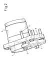
- Figure 2 shows the bearing 5 from the side with fastening screws 2, 7 and a contour 6, which is preferably exactly below the protective bracket 3.
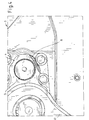
- FIG. 3 shows a tracked vehicle 1 with a torsion bar bearing 9 and a drive wheel 10 (partially shown).
- the protective bracket 3 is by means of screws 2 above the bearing flange attached.
- the protective bracket 3 is attached by means of, for example, fastening screws 2 to the bearing flange 4 of the torsion bars 9 and a roller arm 11 in such a way that the front contour 6 of the bearing flange 4 is protected against mechanical damage from the traveling chain of the tracked vehicle 1 passing by.
- the protective bracket 3 has a semicircular shape and is fastened above the swing arm flange 4 by means of the suitable fastening, preferably in a positive manner. The contour 6 of the swing arm flange 4 located under the protective bracket 3 is thus protected against mechanical influences from outside and from the side.
- the protective bracket 3 is designed as a web curved approximately to a semicircle, so that the torsion bar or torsion bar bearing 9 mounted in the center of the curvature in the bearing remains visible from the outside.
- the protective bracket 3 is made somewhat larger than the underlying contour 6 of the bearing flange 4, the protective bracket 3 preferably completely covering the outer edge of the contour 6.
- the protective bracket 3 is cut out, for example, of plate material of a certain thickness.
- the protective bracket 3 can be fastened to the bearing flange 4 by means of, for example, three extended special screws, which, on the one hand, fasten the bearing 5 in the vehicle housing 1 as fastening screws 7, the screws 7 being designed as a through screw or bolt thread part with respect to through holes in the protective bracket 3 and the protective bracket 3 is attached to screw 7 using screw nut 2.
- the protective bracket 3 can be replaced when a corresponding number of fastening screws 7 against extended special screws and appropriate attachment as retrofit applied to various tracked vehicles to protect the swing arm flange 4 become.
- Figure 4 shows a torsion bar 9 and a roller arm 11 with the bearing flange 4 without a protective bracket 3 with damage 8 to a vehicle 1 after one Use driving. This prevents the present solution.
Landscapes
- Engineering & Computer Science (AREA)
- Chemical & Material Sciences (AREA)
- Combustion & Propulsion (AREA)
- Transportation (AREA)
- Mechanical Engineering (AREA)
- Vehicle Body Suspensions (AREA)
- Axle Suspensions And Sidecars For Cycles (AREA)
- Automotive Seat Belt Assembly (AREA)
- Discharge By Other Means (AREA)
- Seats For Vehicles (AREA)
- Toys (AREA)
- Arrangement And Driving Of Transmission Devices (AREA)
Abstract
Description
- Figur 1:
- Lagerteil mit Schutzbügel
- Figur 2:
- Lagerteil mit Schutzbügel, gedrehte Ansicht
- Figur 3:
- Schutzbügel am Fahrzeug angebaut
- Figur 4:
- Beschädigung eines Lagerflansches nach dem Stand der Technik
Praktisch kann der Schutzbügel 3 mittels beispielsweise drei verlängerter Spezialschrauben, welche als Befestigungsschrauben 7 einerseits die Lagerung 5 im Fahrzeuggehäuse 1 befestigen, am Lagerflansch 4 befestigt werden, wobei die Schrauben 7 als Durchgangsschraube bzw. Bolzengewindeteil bezüglich Durchgangslöchern im Schutzbügel 3 ausgeführt sind und der Schutzbügel 3 mittels Schraubenmutter 2 an Schraube 7 befestigt wird.
Claims (7)
- Vorrichtung für den Schutz des Schwingarmflansches (4) an der Schwingarmlagerung (5) eines Kettenfahrzeugs (1) links und rechts am Fahrzeug (1), insbesondere bei einem frontgetriebenen Fahrzeug, mit einer Lagerung einer ersten Laufrolle nach dem frontseitigen Antriebsrad (10), dadurch gekennzeichnet, dass ein etwa halbkreisförmiger Schutzbügel (3) mittels geeigneter Befestigung bevorzugt formschlüssig oberhalb auf dem Schwingarmflansch (4) befestigt wird, so dass die unter dem Schutzbügel (3) befindliche Kontur (6) des Schwingarmflansches (4) gegen mechanische Einwirkungen von außen und der Seite geschützt ist.
- Vorrichtung nach Anspruch 1, dadurch gekennzeichnet, dass der Schutzbügel (3) entsprechend der Form der darunterliegenden Kontur (6) des Schwingarmflansches (4) als etwa zum Halbkreis gekrümmter Steg ausgeführt ist, so dass der im Zentrum der Krümmung im Lager gelagerte Drehstab (9) von außen sichtbar bleibt.
- Vorrichtung nach einem der oben genannten Ansprüche, dadurch gekennzeichnet, dass der Schutzbügel (3) zum Schutz des Lagerflansches (4) etwas größer als die darunterliegende Kontur (6) des Lagerflansches (4) ausgeführt wird und der Bügel (3) die Außenkante der Kontur (6) vollständig abdeckt.
- Vorrichtung nach einem der oben genannten Ansprüche, dadurch gekennzeichnet, dass der Schutzbügel (3) aus Plattenmaterial gewisser Dicke ausgeschnitten ist.
- Vorrichtung nach einem der oben genannten Ansprüche, dadurch gekennzeichnet, dass der Schutzbügel (3) mittels beispielsweise drei verlängerter Spezialschrauben, welche als Befestigungsschrauben (7) einerseits die Lagerung (5) im Fahrzeuggehäuse (1) befestigen, am Lagerflansch (4) befestigt wird, wobei die Schrauben als Durchgangsschraube bzw. Bolzengewindeteil bezüglich Durchgangslöchern im Schutzbügel (3) ausgeführt sind und der Schutzbügel (3) mittels Schraubenmutter (2) an Schraube (7) befestigt wird.
- Vorrichtung nach einem der oben genannten Ansprüche, dadurch gekennzeichnet, dass der Schutzbügel (3) bei Austausch einer entsprechenden Anzahl Befestigungsschrauben (7) gegen verlängerte Spezialschrauben und entsprechendem Anbau als Nachrüstung an verschiedenen Kettenfahrzeugen zum Schutz des Schwingarmflansches angewendet werden kann.
- Vorrichtung nach einem der oben genannten Ansprüche, dadurch gekennzeichnet, dass der einfache und schnelle Austausch eines defekten Schutzbügels (3) gegen einen neuen Schutzbügel (3) mittels Lösen und Wiederanziehen von beispielsweise 3 Schrauben (7) ausgeführt werden kann.
Applications Claiming Priority (2)
| Application Number | Priority Date | Filing Date | Title |
|---|---|---|---|
| DE20306394U | 2003-04-24 | ||
| DE20306394U DE20306394U1 (de) | 2003-04-24 | 2003-04-24 | Verschleißschutz Schwingarm eines Kettenfahrzeuges |
Publications (3)
| Publication Number | Publication Date |
|---|---|
| EP1470994A2 true EP1470994A2 (de) | 2004-10-27 |
| EP1470994A3 EP1470994A3 (de) | 2004-11-10 |
| EP1470994B1 EP1470994B1 (de) | 2006-03-22 |
Family
ID=27675387
Family Applications (1)
| Application Number | Title | Priority Date | Filing Date |
|---|---|---|---|
| EP04001527A Expired - Lifetime EP1470994B1 (de) | 2003-04-24 | 2004-01-24 | Verschleissschutz Schwingarm eines Kettenfahrzeuges |
Country Status (4)
| Country | Link |
|---|---|
| EP (1) | EP1470994B1 (de) |
| AT (1) | ATE320957T1 (de) |
| DE (2) | DE20306394U1 (de) |
| NO (1) | NO326077B1 (de) |
Families Citing this family (1)
| Publication number | Priority date | Publication date | Assignee | Title |
|---|---|---|---|---|
| DE102008045945B4 (de) | 2008-09-04 | 2012-08-02 | Bundesrepublik Deutschland, vertreten durch das Bundesministerium der Verteidigung, vertreten durch das Bundesamt für Wehrtechnik und Beschaffung | Verschleißschutz für Kettenfahrzeug |
Citations (1)
| Publication number | Priority date | Publication date | Assignee | Title |
|---|---|---|---|---|
| DE19717516A1 (de) | 1997-04-25 | 1998-10-29 | Kuka Wehrtechnik Gmbh | Verfahren und Vorrichtung zum Richten eines deformierten Lagerflansches in einem Kettenfahrzeug |
Family Cites Families (3)
| Publication number | Priority date | Publication date | Assignee | Title |
|---|---|---|---|---|
| FR1339784A (fr) * | 1962-11-09 | 1963-10-11 | Rheinstahl Hanomag Ag | Châssis auxiliaire pour le train porteur d'un char de combat |
| AT406248B (de) * | 1997-02-11 | 2000-03-27 | Steyr Daimler Puch Ag | Kraftfahrzeug mit an schwingarmen aufgehängten rädern |
| JP2001301670A (ja) * | 2000-04-21 | 2001-10-31 | Mitsubishi Agricult Mach Co Ltd | クローラ型走行装置のクローラ防護ガイド |
-
2003
- 2003-04-24 DE DE20306394U patent/DE20306394U1/de not_active Expired - Lifetime
-
2004
- 2004-01-24 DE DE502004000357T patent/DE502004000357D1/de not_active Expired - Lifetime
- 2004-01-24 EP EP04001527A patent/EP1470994B1/de not_active Expired - Lifetime
- 2004-01-24 AT AT04001527T patent/ATE320957T1/de active
- 2004-01-27 NO NO20040359A patent/NO326077B1/no not_active IP Right Cessation
Patent Citations (1)
| Publication number | Priority date | Publication date | Assignee | Title |
|---|---|---|---|---|
| DE19717516A1 (de) | 1997-04-25 | 1998-10-29 | Kuka Wehrtechnik Gmbh | Verfahren und Vorrichtung zum Richten eines deformierten Lagerflansches in einem Kettenfahrzeug |
Also Published As
| Publication number | Publication date |
|---|---|
| DE20306394U1 (de) | 2003-07-31 |
| NO20040359L (no) | 2004-10-25 |
| ATE320957T1 (de) | 2006-04-15 |
| EP1470994B1 (de) | 2006-03-22 |
| EP1470994A3 (de) | 2004-11-10 |
| DE502004000357D1 (de) | 2006-05-11 |
| NO326077B1 (no) | 2008-09-15 |
Similar Documents
| Publication | Publication Date | Title |
|---|---|---|
| DE2816561B2 (de) | System vus Schienenrad und Gleis für Schienenfahrzeuge | |
| DE102016102289B4 (de) | Fahrwerk für ein Nutzfahrzeug | |
| DE102011119153A1 (de) | Kardangelenkanordnung und eine kardangelenk-schutzvorrichtung | |
| EP1470994B1 (de) | Verschleissschutz Schwingarm eines Kettenfahrzeuges | |
| DE2520795A1 (de) | Befestigungsvorrichtung fuer einen schwingtraeger eines raupenfahrzeuges | |
| DE4121737C2 (de) | ||
| DE2518711B2 (de) | Raupenfahrzeuggestell | |
| DE2755412B2 (de) | Vorrichtung zur Verbindung von Kettkörpern einer Gleiskette | |
| DE852044C (de) | Kettenrolle | |
| AT413971B (de) | Gefederte aufhängung einer starrachse am fahrgestell-rahmen eines fahrzeugs, insbesondere lastkraftwagens oder omnibusses | |
| DE1108035B (de) | Spannvorrichtung fuer Rollenketten | |
| DE102015101535B4 (de) | Verstärkungseinheit für LKW-Auflieger und LKW-Auflieger mit einer solchen Verstärkungseinheit | |
| DE2922407C2 (de) | Laufradanordnung für Kran- und Katzlaufwerke | |
| DE371714C (de) | Klemmbefestigung fuer Greifer oder Hilfsfelgen an Triebraedern fuer Zugmaschinen | |
| DE1480754C3 (de) | Gleiskette, insbesondere für Kraftfahrzeuge | |
| EP1732773B1 (de) | Vorrichtung zur lösbaren anbringung einer traktionshilfe an einem eine felge und einen reifen mit lauffläche aufweisenden fahrzeugrad | |
| DE69708063T2 (de) | Radaufhängung | |
| DE569820C (de) | Radkranzsicherung | |
| DE202005004964U1 (de) | Aufhängung für eine Fahrzeugachse | |
| EP4309983A2 (de) | Dreirädriges fahrzeug und umrüsteinheit für ein fahrzeug | |
| DE9404592U1 (de) | Seitenschutz für Fahrzeuge mit hochliegendem Fahrzeugrahmen | |
| DE202013102319U1 (de) | Schwenkrollenbaugruppe für einen Rollstuhl | |
| DE4225801C1 (de) | ||
| DE1273350B (de) | Gleitschutzvorrichtung fuer Luftreifen von Kraftfahrzeugen | |
| DE29700060U1 (de) | Luftfedersystem mit Schutzvorrichtung vor Bruch des Tragarmes |
Legal Events
| Date | Code | Title | Description |
|---|---|---|---|
| PUAI | Public reference made under article 153(3) epc to a published international application that has entered the european phase |
Free format text: ORIGINAL CODE: 0009012 |
|
| PUAL | Search report despatched |
Free format text: ORIGINAL CODE: 0009013 |
|
| AK | Designated contracting states |
Kind code of ref document: A2 Designated state(s): AT BE BG CH CY CZ DE DK EE ES FI FR GB GR HU IE IT LI LU MC NL PT RO SE SI SK TR |
|
| AX | Request for extension of the european patent |
Extension state: AL LT LV MK |
|
| AK | Designated contracting states |
Kind code of ref document: A3 Designated state(s): AT BE BG CH CY CZ DE DK EE ES FI FR GB GR HU IE IT LI LU MC NL PT RO SE SI SK TR |
|
| AX | Request for extension of the european patent |
Extension state: AL LT LV MK |
|
| RIC1 | Information provided on ipc code assigned before grant |
Ipc: 7B 62D 55/14 A Ipc: 7B 62D 55/104 B |
|
| 17P | Request for examination filed |
Effective date: 20041210 |
|
| RTI1 | Title (correction) |
Free format text: RADIUS ARM WITH WEAR PROTECTION FOR A TRACKED VEHICLE |
|
| GRAP | Despatch of communication of intention to grant a patent |
Free format text: ORIGINAL CODE: EPIDOSNIGR1 |
|
| GRAS | Grant fee paid |
Free format text: ORIGINAL CODE: EPIDOSNIGR3 |
|
| AKX | Designation fees paid |
Designated state(s): AT DE GR IT NL SE |
|
| RAP1 | Party data changed (applicant data changed or rights of an application transferred) |
Owner name: RHEINMETALL LANDSYSTEME GMBH |
|
| GRAA | (expected) grant |
Free format text: ORIGINAL CODE: 0009210 |
|
| AK | Designated contracting states |
Kind code of ref document: B1 Designated state(s): AT DE GR IT NL SE |
|
| PG25 | Lapsed in a contracting state [announced via postgrant information from national office to epo] |
Ref country code: IT Free format text: LAPSE BECAUSE OF FAILURE TO SUBMIT A TRANSLATION OF THE DESCRIPTION OR TO PAY THE FEE WITHIN THE PRESCRIBED TIME-LIMIT;WARNING: LAPSES OF ITALIAN PATENTS WITH EFFECTIVE DATE BEFORE 2007 MAY HAVE OCCURRED AT ANY TIME BEFORE 2007. THE CORRECT EFFECTIVE DATE MAY BE DIFFERENT FROM THE ONE RECORDED. Effective date: 20060322 |
|
| REF | Corresponds to: |
Ref document number: 502004000357 Country of ref document: DE Date of ref document: 20060511 Kind code of ref document: P |
|
| REG | Reference to a national code |
Ref country code: SE Ref legal event code: TRGR |
|
| REG | Reference to a national code |
Ref country code: GR Ref legal event code: EP Ref document number: 20060401744 Country of ref document: GR |
|
| PLBE | No opposition filed within time limit |
Free format text: ORIGINAL CODE: 0009261 |
|
| STAA | Information on the status of an ep patent application or granted ep patent |
Free format text: STATUS: NO OPPOSITION FILED WITHIN TIME LIMIT |
|
| 26N | No opposition filed |
Effective date: 20061227 |
|
| PGFP | Annual fee paid to national office [announced via postgrant information from national office to epo] |
Ref country code: NL Payment date: 20160120 Year of fee payment: 13 |
|
| PGFP | Annual fee paid to national office [announced via postgrant information from national office to epo] |
Ref country code: IT Payment date: 20160127 Year of fee payment: 13 Ref country code: DE Payment date: 20160120 Year of fee payment: 13 |
|
| PGFP | Annual fee paid to national office [announced via postgrant information from national office to epo] |
Ref country code: AT Payment date: 20160121 Year of fee payment: 13 Ref country code: GR Payment date: 20160121 Year of fee payment: 13 Ref country code: SE Payment date: 20160120 Year of fee payment: 13 |
|
| REG | Reference to a national code |
Ref country code: DE Ref legal event code: R119 Ref document number: 502004000357 Country of ref document: DE |
|
| REG | Reference to a national code |
Ref country code: NL Ref legal event code: MM Effective date: 20170201 |
|
| REG | Reference to a national code |
Ref country code: AT Ref legal event code: MM01 Ref document number: 320957 Country of ref document: AT Kind code of ref document: T Effective date: 20170124 |
|
| PG25 | Lapsed in a contracting state [announced via postgrant information from national office to epo] |
Ref country code: AT Free format text: LAPSE BECAUSE OF NON-PAYMENT OF DUE FEES Effective date: 20170124 Ref country code: GR Free format text: LAPSE BECAUSE OF NON-PAYMENT OF DUE FEES Effective date: 20170811 |
|
| PG25 | Lapsed in a contracting state [announced via postgrant information from national office to epo] |
Ref country code: SE Free format text: LAPSE BECAUSE OF NON-PAYMENT OF DUE FEES Effective date: 20170125 Ref country code: NL Free format text: LAPSE BECAUSE OF NON-PAYMENT OF DUE FEES Effective date: 20170201 Ref country code: DE Free format text: LAPSE BECAUSE OF NON-PAYMENT OF DUE FEES Effective date: 20170801 |
|
| PG25 | Lapsed in a contracting state [announced via postgrant information from national office to epo] |
Ref country code: IT Free format text: LAPSE BECAUSE OF NON-PAYMENT OF DUE FEES Effective date: 20170124 |