EP1470668B1 - Systems and methods for documenting networks with electronic modules included in ports and devices - Google Patents
Systems and methods for documenting networks with electronic modules included in ports and devices Download PDFInfo
- Publication number
- EP1470668B1 EP1470668B1 EP03707574A EP03707574A EP1470668B1 EP 1470668 B1 EP1470668 B1 EP 1470668B1 EP 03707574 A EP03707574 A EP 03707574A EP 03707574 A EP03707574 A EP 03707574A EP 1470668 B1 EP1470668 B1 EP 1470668B1
- Authority
- EP
- European Patent Office
- Prior art keywords
- port
- query
- destination device
- source device
- network
- Prior art date
- Legal status (The legal status is an assumption and is not a legal conclusion. Google has not performed a legal analysis and makes no representation as to the accuracy of the status listed.)
- Expired - Lifetime
Links
- 238000000034 method Methods 0.000 title claims description 10
- 230000004044 response Effects 0.000 claims abstract description 45
- 238000012544 monitoring process Methods 0.000 claims description 2
- 238000004891 communication Methods 0.000 abstract description 12
- 230000008901 benefit Effects 0.000 description 4
- 238000012360 testing method Methods 0.000 description 4
- 239000004020 conductor Substances 0.000 description 2
- 239000000835 fiber Substances 0.000 description 2
- 230000037361 pathway Effects 0.000 description 2
- 238000001514 detection method Methods 0.000 description 1
- 238000005516 engineering process Methods 0.000 description 1
- 230000007717 exclusion Effects 0.000 description 1
- 238000003780 insertion Methods 0.000 description 1
- 230000037431 insertion Effects 0.000 description 1
- 238000007726 management method Methods 0.000 description 1
- 230000007246 mechanism Effects 0.000 description 1
- 230000008569 process Effects 0.000 description 1
Images

Classifications
-
- H—ELECTRICITY
- H04—ELECTRIC COMMUNICATION TECHNIQUE
- H04L—TRANSMISSION OF DIGITAL INFORMATION, e.g. TELEGRAPHIC COMMUNICATION
- H04L41/00—Arrangements for maintenance, administration or management of data switching networks, e.g. of packet switching networks
- H04L41/12—Discovery or management of network topologies
Definitions
- LAN local area network
- Such a documentation system provides many advantages, including facilitating the planning and revision processes, the determination of the location of the physical area of a discontinuity in the network path, and the determination of the physical locations of destination devices.
- EP739110 relates to monitoring of neighbouring information frames in a network to build a network topology.
- EP1152569 relates to building a data base of identification codes relating to active and passive components in a network.
- US01033550 relates to real time update of a network topology by requesting network elements to identify themselves electronic serial numbers and constructing a network topology.
- WO02069565 relates to a network documentation system in which a source device sends query signals to a data port and destination device.
- DE 198 12901 is a further example.
- a documentation system for a network having a source device which is connected to at least one destination device through at least one intermediate network path element.
- the source device has the capability to transmit a query signal directed to any destination device to which it is connected and each destination device has the capability to send a response signal containing its identification code back to the source device.
- the source device has the capability to transmit a query signal directed to any intermediate network path element which has a physical location in a designated zone and an electronic module in the intermediate network path element has the capability to return a response signal containing its identification code back to the source device.
- the source may be adapted to re-send a query signal if one or more response signals are not received.
- the network documentation system utilizes software to direct the source device to sequentially send query signals directed to destination devices to which it is connected and to intermediate network path elements in each designated zone to which it is connected.
- the response signals are interpreted by the software to document the network configuration.
- FIG. 1 is a schematic view of a documentation system in accordance with a first embodiment of the invention.
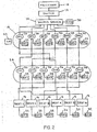
- FIG. 2 is a schematic view of a documentation system in accordance with a second embodiment of the invention.
- electronic modules are placed into electronic communication networks with corresponding ports or nodes of the network such that connecting apparatus, connecting the respective ports or nodes to a source device, also provide a mechanism by which query and response signals may be routed between the source device and the connected ports or nodes in the system in the same manner that data signals may be transmitted between them.
- the signals may be transmitted over the same or a different medium from the data signals (e.g., common or separate wire or fiber).
- the electronic modules have associated identification elements that may have a single component or multiple components, and the modules are capable of receiving and recognizing query signals directed to them and responding by transmitting their identification code back to the source device.
- the system may utilize signals directed toward and received from all of the respective data ports or nodes in the system and thereby formulate a "map" of the entire system as it is physically configured.
- a source device i.e. a switch
- a query signal through one designated network path that causes any destination device, i.e. a personal computer, that receiver the query to transmit a response signal containing its identification code to the source device.
- the inventive documentation and fault detection system contemplates the preferable use of electronic modules in every final destination device within a network, as well as in every network port which connects the source device to the final destination devices.
- Documentation systems and methods according to the present invention may be employed in Ethernet networks, including switched Ethernet networks.
- Each module can receive a query signal from a source, e.g., a switch, and ascertain whether the signal is directed to it by the use of identification codes.
- each electronic module which is in a designated physical location zone within the system has a unique zone address code.
- the ports and their corresponding modules may be stratified into "zones" based on their relative proximity, in an electrical or communications sense, to the source device and/or the final destination device.
- every port/module within a particular zone has the same zone addressing information, however each module retains a unique identification code which is transmitted to the source device in response to a query directed to it.
- a typical network may include a pair of patch panel ports for cross-connecting between a source and one or more destinations.
- the group of patch panel ports (and the electronic modules contained therein) closer to the source from a communications standpoint i.e., the signal path direction
- the next group of ports/modules along the signal path i.e., the patch panel ports closer to the destination devices
- the destination devices would be classified as zone 3.
- the source sequentially sends a signal along respective output paths directed to any module along the path having a specified zone address.
- the one module in such zone along each respective path then, in turn, transmits back to the source when it receives the signal intended for its zone.
- the return signal includes the identification code of the module returning the signal.
- Each electronic module in the system would require a power supply which, in various embodiments of the invention, could be provided by a pair of conductors which could also be signal pairs or a battery.
- the system could use one or more of the signal pairs to receive and transmit signals to and from particular electronic modules, including those associated with particular destination devices, sources, and network ports there between from a communications standpoint.
- a fiber optic or other LAN system could incorporate two conductors in each cable to be adapted for the same purpose.
- a computer or processor 10 is connected to a switch 12.
- the switch may periodically or on-demand poll one or more of the data ports in the system to ascertain information about the ports. Alternatively or additionally, this polling may be accomplished using a software module provided on a computer or processor. Such polling may occur on a zone-by-zone basis, with the source device sequentially sending a signal, such as a query signal, along respective output lines directed to any electronic module along the path having the specified zone address. The identified module may then return its identification code back to the source. In this manner, the entire system may effectively be mapped (i.e., documented).
- the switch may preferably be in communications with a source device 14 and one or more destination devices 16.
- a first zone 18 of data ports 20 may preferably be congregated on a single patch panel or network rack, and each of the data ports 20 is electrically connected directly with the source device 14.
- Each of the data ports 20, identified as “DP” in the figures, has an electronic module 22, identified as “EM” in the figures, in electrical communication therewith.
- the first zone 18 of data ports includes a test port 23 disposed proximately thereto for permitting connection of a test plug.
- a second zone 24 of data ports 26 may also be congregated on another patch panel or network rack, and each of the data ports 26 is electrically connected directly with one of the destination devices 16.
- Each of the data ports 26 has an electronic module 28 in electrical communication therewith.
- the second zone 24 of data ports includes a test port 29 disposed proximately thereto for permitting connection of a test plug.
- the source device 14 preferably includes an electronic module 30 in electrical communication therewith and the destination devices 16 each include an electronic module 32 in electrical communication therewith.
- connective lines represent possible electrical connections that may be achieved by the use of patch cords and cables, and an exemplary system having six destination devices connected to a source device is shown.
- FIG. 2 illustrates an interconnect configuration wherein the first zone 18 is a patch panel and the second zone 24 are the outlet ports (e.g ., wall outlet jacks) to which the destination devices are connected.
- the destination devices may be provided with state of the art electronic modules with common address codes and unique identification codes.
- the outlet ports are identified as "DO" in FIG. 2 .
- the destination outlets while not qualitatively different than the data ports 7-12 of FIG. 1 , are disposed proximately to the destination devices 16 to which they are connected. This provides the benefit of knowing approximately where a particular destination device is physically located based on its proximity to a destination outlet which is fixed in the physical world. Thus, by focusing on the identification code of the electronic module of the particular destination outlet, rather than that of the destination device itself, the approximate location of the destination device may be ascertained by the system.
- each intersection i.e., LAN port
- each intersection has associated with it an electronic module having a zone address code, and because response signals from a particular electronic module include the identification code of the module, pathways from a source to a destination can be more clearly identified on a link-by-link or zone-by-zone basis. Physical locations of ports and destination devices and revision instructions can be more efficie tly determined for a particular reconfiguration.
- this same query signal also causes one or a plurality of ports which contain electronic modules along said network path to add its response containing its identification code as a suffix or a series of suffixes to the response from the destination device or the various responses could be received in any order.
- only the port to which the destination device is connected to is equipped with an electronic module.
- This electronic module responds to a query from the source device after a pre-set time delay which is long enough for the response from the destination device to have occurred.
- the source device therefore receives the response from the destination device followed by the response from said port.
- additional electronic modules are located in ports in specified zones in the network path between said port and the source device and each zone electronic module has a designated time delay to correspond to its designated zone. In this manner, the entire path between the switch and ultimate device can be documented.
- the port to which the destination device is connected is equipped with an electronic module.
- Said electronic module receives the query followed by the response from the destination device or it receives only the response from the destination device and it sends its response containing its identification code.
- additional electronic modules are located in ports in specified zones in the network path. These electronic modules receive the query followed by the response from the destination device or they receive only the response from the destination device followed by the successive responses from each of said ports which are closer to the destination device along the network path than it is and it then sends its response containing its identification code.
- only the port to which the destination device is connected is equipped with an electronic module which responds immediately with its identification code when a query from the source device is received. Subsequently, the destination device responds to the source query with its identification code.
- only the port to which the destination device is connected is equipped with an electronic module which responds with its identification code after a query from the source device is received.
- the destination device responds to the same query with its identification code after it is received.
- the above two identification codes could be received in any order. If there is a collision of signals and both responses are not received by the source device, the query is repeated.
- the port to which the destination device is connected is equipped with an electronic module which receives and stores the responses from the destination device. It then sends its total response which includes the response from the destination device plus its identification code.
- each electronic module receives and stores, the responses from the destination device and the responses from all electronic modules for each said port which is closer to the destination device along the network path than it is. It then sends its total response which includes said stored responses followed by its individual response containing its identification code.
- the port to which the destination device is connected is equipped with an electronic module.
- an electronic module in the destination device sends an inquiry to the electronic module in the port and it responds to the destination device with its identification code.
- the destination device responds to the source device with its identification code followed by the port identification code.
- An application of the above embodiments is a VoIP telephone wherein it is desirable to know the physical location of the telephone in the event an emergency 911 call is made from the telephone. While the physical location of the telephone can be changed, the physical location of the port to which it is connected is known if the port's identification code is known. Therefore, the physical location of an emergency call made with any telephone connected to a particular port is known by the identification code associated with said port. Associations between identification codes and specific ports may be recorded in a table or map containing physical locations along with identification codes of ports at the physical locations.
- An advantage of these documentation systems is that they can be attained by adding said electronic modules and altering the software of said State of the Art documentation systems. The generation of any additional query signals to those generated by said State of the Art system is not required.
- the present invention contemplates many embodiments not specifically described, and the explicitly described embodiments should be considered to be exemplary rather than definitional.
- the present invention may be employed in a network system having a distinct indicator, such as an LED, adjacent some or all of the LAN ports in the network. Such indicators may then be used to assist the revisor in identifying LAN ports requiring the insertion or removal of a cord plug.
Landscapes
- Engineering & Computer Science (AREA)
- Computer Networks & Wireless Communication (AREA)
- Signal Processing (AREA)
- Small-Scale Networks (AREA)
- Variable-Direction Aerials And Aerial Arrays (AREA)
- Data Exchanges In Wide-Area Networks (AREA)
Applications Claiming Priority (5)
| Application Number | Priority Date | Filing Date | Title |
|---|---|---|---|
| US35282602P | 2002-01-30 | 2002-01-30 | |
| US352826P | 2002-01-30 | ||
| US10/353,640 US7656903B2 (en) | 2002-01-30 | 2003-01-29 | System and methods for documenting networks with electronic modules |
| US353640 | 2003-01-29 | ||
| PCT/US2003/002574 WO2003065651A2 (en) | 2002-01-30 | 2003-01-30 | Systems and methods for documenting networks with electronic modules in ports and devices |
Publications (2)
| Publication Number | Publication Date |
|---|---|
| EP1470668A2 EP1470668A2 (en) | 2004-10-27 |
| EP1470668B1 true EP1470668B1 (en) | 2009-09-16 |
Family
ID=27669074
Family Applications (1)
| Application Number | Title | Priority Date | Filing Date |
|---|---|---|---|
| EP03707574A Expired - Lifetime EP1470668B1 (en) | 2002-01-30 | 2003-01-30 | Systems and methods for documenting networks with electronic modules included in ports and devices |
Country Status (8)
| Country | Link |
|---|---|
| US (1) | US7656903B2 (enExample) |
| EP (1) | EP1470668B1 (enExample) |
| JP (2) | JP2005516537A (enExample) |
| CN (1) | CN100547966C (enExample) |
| AT (1) | ATE443386T1 (enExample) |
| AU (1) | AU2003209413A1 (enExample) |
| DE (1) | DE60329271D1 (enExample) |
| WO (1) | WO2003065651A2 (enExample) |
Families Citing this family (36)
| Publication number | Priority date | Publication date | Assignee | Title |
|---|---|---|---|---|
| US6480510B1 (en) | 1998-07-28 | 2002-11-12 | Serconet Ltd. | Local area network of serial intelligent cells |
| US6956826B1 (en) | 1999-07-07 | 2005-10-18 | Serconet Ltd. | Local area network for distributing data communication, sensing and control signals |
| US6690677B1 (en) | 1999-07-20 | 2004-02-10 | Serconet Ltd. | Network for telephony and data communication |
| US6549616B1 (en) | 2000-03-20 | 2003-04-15 | Serconet Ltd. | Telephone outlet for implementing a local area network over telephone lines and a local area network using such outlets |
| IL135744A (en) | 2000-04-18 | 2008-08-07 | Mosaid Technologies Inc | Telephone communication system over a single telephone line |
| US6961303B1 (en) | 2000-09-21 | 2005-11-01 | Serconet Ltd. | Telephone communication system and method over local area network wiring |
| US7028087B2 (en) * | 2001-02-23 | 2006-04-11 | Panduit Corp. | Network documentation system with electronic modules |
| IL144158A (en) | 2001-07-05 | 2011-06-30 | Mosaid Technologies Inc | Socket for connecting an analog telephone to a digital communications network that carries digital voice signals |
| US7436842B2 (en) | 2001-10-11 | 2008-10-14 | Serconet Ltd. | Outlet with analog signal adapter, a method for use thereof and a network using said outlet |
| US7376734B2 (en) | 2002-02-14 | 2008-05-20 | Panduit Corp. | VOIP telephone location system |
| US7519000B2 (en) | 2002-01-30 | 2009-04-14 | Panduit Corp. | Systems and methods for managing a network |
| IL152824A (en) | 2002-11-13 | 2012-05-31 | Mosaid Technologies Inc | A socket that can be connected to and the network that uses it |
| IL157787A (en) | 2003-09-07 | 2010-12-30 | Mosaid Technologies Inc | Modular outlet for data communications network |
| US20050141431A1 (en) | 2003-08-06 | 2005-06-30 | Caveney Jack E. | Network managed device installation and provisioning technique |
| US7207846B2 (en) | 2003-11-24 | 2007-04-24 | Panduit Corp. | Patch panel with a motherboard for connecting communication jacks |
| IL159838A0 (en) | 2004-01-13 | 2004-06-20 | Yehuda Binder | Information device |
| IL160417A (en) | 2004-02-16 | 2011-04-28 | Mosaid Technologies Inc | Unit added to the outlet |
| CN101099397B (zh) | 2004-05-03 | 2012-02-08 | 泛达公司 | 加电的配线架 |
| CN101053262B (zh) | 2004-11-03 | 2012-06-13 | 泛达公司 | 用于配线板接插线文件编制和修正的方法和装置 |
| US7873058B2 (en) | 2004-11-08 | 2011-01-18 | Mosaid Technologies Incorporated | Outlet with analog signal adapter, a method for use thereof and a network using said outlet |
| US7234944B2 (en) * | 2005-08-26 | 2007-06-26 | Panduit Corp. | Patch field documentation and revision systems |
| US7978845B2 (en) | 2005-09-28 | 2011-07-12 | Panduit Corp. | Powered patch panel |
| US7782202B2 (en) | 2006-10-31 | 2010-08-24 | Corning Cable Systems, Llc | Radio frequency identification of component connections |
| US7772975B2 (en) | 2006-10-31 | 2010-08-10 | Corning Cable Systems, Llc | System for mapping connections using RFID function |
| US8264355B2 (en) | 2006-12-14 | 2012-09-11 | Corning Cable Systems Llc | RFID systems and methods for optical fiber network deployment and maintenance |
| US7760094B1 (en) | 2006-12-14 | 2010-07-20 | Corning Cable Systems Llc | RFID systems and methods for optical fiber network deployment and maintenance |
| US7547150B2 (en) | 2007-03-09 | 2009-06-16 | Corning Cable Systems, Llc | Optically addressed RFID elements |
| US8382501B2 (en) * | 2008-07-08 | 2013-02-26 | Commscope Inc. Of North Carolina | Systems and methods of identifying connections in a communications patching system using common-mode channel signal transmissions |
| US20100011097A1 (en) * | 2008-07-11 | 2010-01-14 | Terry Cobb | Methods of Using Control Communications to Identify Devices that are Connected Through a Communications Patching System and Related Communications Patching Systems |
| US8248208B2 (en) | 2008-07-15 | 2012-08-21 | Corning Cable Systems, Llc. | RFID-based active labeling system for telecommunication systems |
| US8731405B2 (en) | 2008-08-28 | 2014-05-20 | Corning Cable Systems Llc | RFID-based systems and methods for collecting telecommunications network information |
| US9538262B2 (en) * | 2009-08-21 | 2017-01-03 | Commscope, Inc. Of North Carolina | Systems, equipment and methods for automatically tracking cable connections and for identifying work area devices and related methods of operating communications networks |
| US8994547B2 (en) | 2009-08-21 | 2015-03-31 | Commscope, Inc. Of North Carolina | Systems for automatically tracking patching connections to network devices using a separate control channel and related patching equipment and methods |
| US9563832B2 (en) | 2012-10-08 | 2017-02-07 | Corning Incorporated | Excess radio-frequency (RF) power storage and power sharing RF identification (RFID) tags, and related connection systems and methods |
| US12197997B2 (en) | 2020-03-09 | 2025-01-14 | Panduit Corp. | Cable management system and method |
| US11347955B2 (en) | 2020-03-09 | 2022-05-31 | Panduit Corp. | Cable management system and method |
Citations (1)
| Publication number | Priority date | Publication date | Assignee | Title |
|---|---|---|---|---|
| DE19812901A1 (de) * | 1998-03-18 | 1999-09-23 | Bb Data Inf & Komm Syst Gmbh | Computernetz mit Daten- oder Kommunikationsendsystemen |
Family Cites Families (152)
| Publication number | Priority date | Publication date | Assignee | Title |
|---|---|---|---|---|
| US3052842A (en) | 1959-10-15 | 1962-09-04 | Lockheed Aircraft Corp | Patchcord connection aid and checking system |
| US3573792A (en) | 1968-11-12 | 1971-04-06 | Us Navy | Universal display panel |
| US3573789A (en) | 1968-12-13 | 1971-04-06 | Ibm | Method and apparatus for increasing image resolution |
| US3914561A (en) | 1971-12-08 | 1975-10-21 | American Telephone & Telegraph | Apparatus and method for tracing jumpers in a main distributing frame |
| US4018997A (en) | 1974-05-10 | 1977-04-19 | Amp Incorporated | Pluggable key set telephone cross connect device |
| CA1012270A (en) | 1974-06-19 | 1977-06-14 | Arie Verhagen | Modular interchange termination system |
| US4072827A (en) | 1976-09-15 | 1978-02-07 | Oman Robert C | Telephone patching apparatus |
| US4096359A (en) | 1976-10-12 | 1978-06-20 | International Standard Electric Corporation | Key telephone system interconnection apparatus |
| US4196316A (en) | 1977-09-13 | 1980-04-01 | Bell Telephone Laboratories, Incorporated | Program controlled communication system having individually rearrangeable line selection |
| JPS5895927A (ja) | 1981-12-02 | 1983-06-07 | 三菱電機株式会社 | 保護継電方式 |
| US4673246A (en) | 1984-08-24 | 1987-06-16 | Pacific Bell | Patch unit for fiber optic distribution network |
| KR870011719A (ko) | 1986-05-28 | 1987-12-26 | 쓰지 하루오 | 접속장치 |
| US4773867A (en) | 1986-07-02 | 1988-09-27 | Amp Incorporated | Premise distribution cross connect apparatus |
| JPS63139499A (ja) | 1986-12-02 | 1988-06-11 | Toshiba Corp | 電子交換機のポ−ト接続方式 |
| AT387873B (de) | 1987-06-25 | 1989-03-28 | Sprecher Energie Oesterreich | Einrichtung zur steuerung und ueberwachung einer elektrischen energieverteilungsanlage |
| US4901004A (en) | 1988-12-09 | 1990-02-13 | King Fred N | Apparatus and method for mapping the connectivity of communications systems with multiple communications paths |
| US4937825A (en) | 1988-06-15 | 1990-06-26 | International Business Machines | Method and apparatus for diagnosing problems in data communication networks |
| US5111408A (en) | 1988-10-19 | 1992-05-05 | Hewlett-Packard Company | Digital image documentation system |
| US5037167A (en) | 1989-05-01 | 1991-08-06 | Alcatel Na, Inc. | Electrical and fiber optic cable control and management |
| US5107532A (en) | 1989-09-22 | 1992-04-21 | Cable Management International, Inc. | Automated documentation system for a communications network |
| GB2236398A (en) | 1989-09-29 | 1991-04-03 | James Alexander Carter | Self documenting patch panel |
| US5185860A (en) * | 1990-05-03 | 1993-02-09 | Hewlett-Packard Company | Automatic discovery of network elements |
| US5226120A (en) | 1990-05-21 | 1993-07-06 | Synoptics Communications, Inc. | Apparatus and method of monitoring the status of a local area network |
| US5170327A (en) | 1990-11-05 | 1992-12-08 | Adc Telecommunications, Inc. | Distal distribution frame module |
| IL97227A0 (en) | 1991-02-13 | 1992-05-25 | Bynet System Applic Ltd | Patching panel |
| US5297138A (en) * | 1991-04-30 | 1994-03-22 | Hewlett-Packard Company | Determining physical topology across repeaters and bridges in a computer network |
| US5145380A (en) | 1991-06-17 | 1992-09-08 | Homaco, Inc. | Patch panel |
| FR2680067B1 (fr) | 1991-08-01 | 1995-05-12 | Cit Alcatel | Procede de controle d'un repartiteur de lignes; cable auxiliaire, connecteur et repartiteur pour la mise en óoeuvre de ce procede. |
| US5270658A (en) | 1991-08-19 | 1993-12-14 | Epstein Barry M | Means and method for testing and monitoring a circuit breaker panel assembly |
| US5204929A (en) | 1991-09-04 | 1993-04-20 | Reliance Comm/Tec Corporation | Fiber patch panel |
| US5487666A (en) | 1991-12-31 | 1996-01-30 | Digiovanni; Thomas H. | Schematic patch panel |
| US5481738A (en) * | 1992-02-20 | 1996-01-02 | International Business Machines Corporation | Apparatus and method for communicating a quiesce and unquiesce state between elements of a data processing complex |
| US5233501A (en) | 1992-02-27 | 1993-08-03 | Telect, Inc. | Digital telecommunication network cross-connect module having a printed circuit board connected to jack switches |
| US5483467A (en) | 1992-06-10 | 1996-01-09 | Rit Technologies, Ltd. | Patching panel scanner |
| ATE165669T1 (de) | 1992-06-10 | 1998-05-15 | Rit Techn Ltd | Abtaster für steckfeld |
| US5222164A (en) | 1992-08-27 | 1993-06-22 | International Business Machines Corporation | Electrically isolated optical connector identification system |
| CA2081608C (en) | 1992-10-28 | 1998-05-05 | Joseph Octave Regis Morin | Distribution frame and optical connector holder combination |
| US5305405A (en) | 1993-02-25 | 1994-04-19 | Adc Telecommunications, Inc. | Patch cord |
| US5568525A (en) * | 1993-08-19 | 1996-10-22 | International Business Machines Corporation | System and method for connection of multiple protocol terminals |
| US5394503A (en) | 1993-10-08 | 1995-02-28 | Data Switch Corporation | Optical fiber connection monitoring apparatus, patch panel control system and method of using same |
| US5353367A (en) | 1993-11-29 | 1994-10-04 | Northern Telecom Limited | Distribution frame and optical connector holder combination |
| DE69330833T2 (de) | 1993-12-06 | 2002-03-28 | Agilent Technologies Inc., A Delaware Corp. | Stellenidentifizierung in einem Kommunikationssignalisierungsnetz |
| US5432847A (en) | 1994-03-29 | 1995-07-11 | Telect, Inc. | Low frequency telecommunication digital network interface patch panel |
| FR2718546B1 (fr) | 1994-04-08 | 1996-05-31 | Luc Lebeau | Dispositif de liaison informatique entre appareils avec systèmes de communication hétérogènes, clef relative à un tel dispositif. |
| US5684796A (en) | 1994-05-03 | 1997-11-04 | Bay Networks Group, Inc. | Method and apparatus for determining and maintaining agent topology information in a multi-segment network |
| US5550755A (en) | 1994-07-14 | 1996-08-27 | Martin; B. Morgan | Apparatus and method for patch recording and recall |
| US5727055A (en) | 1995-05-17 | 1998-03-10 | Ies Technologies, Inc. | Information communication systems |
| IL110859A (en) | 1994-09-04 | 1999-12-31 | Rit Techn Ltd | Interconnection monitor system for telephone network |
| US5583874A (en) | 1994-12-07 | 1996-12-10 | Infonet Computer Systems, Inc. | 10Base-T portable link tester |
| US5532603A (en) | 1995-01-27 | 1996-07-02 | Fluke Corporation | Cross-talk measurement apparatus with near-end compensation |
| US5790041A (en) | 1995-02-14 | 1998-08-04 | Advanced Micro Devices, Inc. | Apparatus and method to display network connection status on a jack panel |
| US5684959A (en) | 1995-04-19 | 1997-11-04 | Hewlett-Packard Company | Method for determining topology of a network |
| US5546282A (en) | 1995-05-02 | 1996-08-13 | Telect, Inc. | Telecommunication network digital cross-connect panels having insertable modules with printed circuit board mounted coaxial jack switches |
| US5943404A (en) | 1995-07-10 | 1999-08-24 | Adtran, Inc. | Mechanism for providing emergency POTS service in event of loss of power to customer premises equipment for ISDN telephone lines |
| US5754112A (en) | 1995-09-28 | 1998-05-19 | Sun Microsystems, Inc. | Power on, mated, and activity indicator for electronic devices including storage devices |
| WO1997019543A1 (en) | 1995-11-24 | 1997-05-29 | Voelker Technologies, Inc. | Electronic patching system for telecommunications devices |
| US5898837A (en) | 1996-02-23 | 1999-04-27 | Bay Networks, Inc. | Method and apparatus for monitoring a dedicated communications medium in a switched data network |
| US5878030A (en) | 1996-06-19 | 1999-03-02 | Wandel & Goltermann Technologies, Inc. | Test access port for analyzing high-speed local area network switched environment |
| US5876240A (en) | 1997-04-01 | 1999-03-02 | The Whitaker Corp | Stacked electrical connector with visual indicators |
| US6067014A (en) | 1996-08-09 | 2000-05-23 | Wilson; Edwin P. | Cord tamper method and apparatus |
| US5847557A (en) | 1997-06-06 | 1998-12-08 | Fincher; William C. | Wire pair identification method |
| US5764043A (en) | 1996-12-20 | 1998-06-09 | Siecor Corporation | Traceable patch cord and connector assembly and method for locating patch cord ends |
| US5892756A (en) | 1997-01-28 | 1999-04-06 | Mtb Insights, Incorporated | Portable telecommunication network testing device |
| US5944535A (en) | 1997-02-04 | 1999-08-31 | Hubbell Incorporated | Interface panel system for networks |
| US5915993A (en) | 1997-02-27 | 1999-06-29 | Berg Technology, Inc. | Assembly containing a modular jack and a light emitting diode |
| US5923663A (en) | 1997-03-24 | 1999-07-13 | Compaq Computer Corporation | Method and apparatus for automatically detecting media connected to a network port |
| US6421322B1 (en) | 1997-11-17 | 2002-07-16 | Adc Telecommunications, Inc. | System and method for electronically identifying connections of a cross-connect system |
| US6041352A (en) | 1998-01-23 | 2000-03-21 | Hewlett-Packard Company | Response time measuring system and method for determining and isolating time delays within a network |
| US6094261A (en) | 1998-01-29 | 2000-07-25 | L-Com, Inc. | Method and apparatus for distinguishing fiber-optic cables |
| BR9815810A (pt) | 1998-04-13 | 2000-11-28 | Adc Telecommunications Inc | Sistema de monitoração de desempenho e acesso de teste e método para conexão cruzada de redes de comunicação |
| US6002331A (en) | 1998-07-20 | 1999-12-14 | Laor; Herzel | Method and apparatus for identifying and tracking connections of communication lines |
| US6229538B1 (en) | 1998-09-11 | 2001-05-08 | Compaq Computer Corporation | Port-centric graphic representations of network controllers |
| US6381283B1 (en) | 1998-10-07 | 2002-04-30 | Controlnet, Inc. | Integrated socket with chip carrier |
| US6086415A (en) | 1998-10-29 | 2000-07-11 | Hubbell Incorporated | High density modular patch panel |
| US6175865B1 (en) | 1998-11-12 | 2001-01-16 | Hewlett-Packard Company | Apparatus for automatically configuring network media connections |
| US6437894B1 (en) | 1998-12-11 | 2002-08-20 | Fitel Usa Corp. | Fiber distribution shelf assembly for a fiber administration system having integral line tracing capabilities |
| US6434716B1 (en) | 1999-01-29 | 2002-08-13 | Psiber Data Systems Inc. | Network link tester device configured to selectively and automatically couple to a network transmit pair line or a node transmit pair line of a LAN port and determine available operational modes |
| US6078113A (en) | 1999-02-01 | 2000-06-20 | True; Mark E. | Power socket with illuminated plug blade slots |
| US7058024B1 (en) * | 1999-02-03 | 2006-06-06 | Lucent Technologies, Inc. | Automatic telecommunications link identification system |
| US6424710B1 (en) | 1999-02-10 | 2002-07-23 | Avaya Technology Corp. | Method and device for detecting the presence of a patch cord connector in a telecommunications patch system using passive detection sensors |
| US6285293B1 (en) | 1999-02-10 | 2001-09-04 | Avaya Technology Corp. | System and method for addressing and tracing patch cords in a dedicated telecommunications system |
| US6522737B1 (en) | 1999-02-10 | 2003-02-18 | Avaya Technology Corp. | System and method of operation for a telecommunications patch system |
| US6350148B1 (en) | 1999-02-10 | 2002-02-26 | Avaya Technology Corp. | Method and device for detecting the presence of a patch cord connector in a telecommunications patch system |
| US6688910B1 (en) | 1999-02-10 | 2004-02-10 | Avaya Technology Corp. | System and method for automatic addressing of devices in a dedicated telecommunications system |
| US6330307B1 (en) | 1999-02-10 | 2001-12-11 | Avaya Technology Corp. | Display panel overlay structure and method for tracing interface modules in a telecommunications patch system |
| US6234830B1 (en) | 1999-02-10 | 2001-05-22 | Avaya Technology Corp. | Tracing interface module for patch cords in a telecommunications system |
| SG74714A1 (en) | 1999-04-06 | 2001-08-21 | Cablesoft Inc | A system for monitoring connection pattern of data ports |
| MXPA01010075A (es) | 1999-04-06 | 2004-10-29 | Itracks Corp | Un sistema para monitorear el patron de conexion de puertos de datos. |
| US6377987B1 (en) * | 1999-04-30 | 2002-04-23 | Cisco Technology, Inc. | Mechanism for determining actual physical topology of network based on gathered configuration information representing true neighboring devices |
| US6370294B1 (en) | 1999-06-25 | 2002-04-09 | Adc Telecommunications, Inc. | Fiber optic circuit and module with switch |
| US6629269B1 (en) | 1999-07-23 | 2003-09-30 | Fluke Corporation | Apparatus and method for trouble-shooting desktop connectivity problems |
| US6499861B1 (en) | 1999-09-23 | 2002-12-31 | Avaya Technology Corp. | Illuminated patch cord connector ports for use in a telecommunications patch closet having patch cord tracing capabilities |
| US6222908B1 (en) | 1999-09-23 | 2001-04-24 | Avaya Technology Corp. | Method and device for identifying a specific patch cord connector as it is introduced into, or removed from, a telecommunications patch system |
| US6784802B1 (en) | 1999-11-04 | 2004-08-31 | Nordx/Cdt, Inc. | Real time monitoring of cable patch panel |
| US6577243B1 (en) | 1999-12-14 | 2003-06-10 | Alan J. Brown | Method and apparatus for tracing remote ends of networking cables |
| US6601097B1 (en) | 2000-01-10 | 2003-07-29 | International Business Machines Corporation | Method and system for determining the physical location of computers in a network by storing a room location and MAC address in the ethernet wall plate |
| JP2001203691A (ja) * | 2000-01-19 | 2001-07-27 | Nec Corp | ネットワークトラフィック監視システム及びそれに用いる監視方法 |
| US20010033550A1 (en) | 2000-01-28 | 2001-10-25 | Banwell Thomas Clyde | Physical layer auto-discovery for management of network elements |
| US6243510B1 (en) | 2000-03-13 | 2001-06-05 | Apcon, Inc. | Electronically-controllable fiber optic patch panel |
| JP2001297044A (ja) * | 2000-04-13 | 2001-10-26 | Sharp Corp | デジタル情報機器ネットワーク装置 |
| DE20007952U1 (de) | 2000-05-03 | 2000-11-02 | Nowak, Nick, 21368 Boitze | System zur Erkennung von inaktiven Komponenten in Netzwerken |
| US7752024B2 (en) * | 2000-05-05 | 2010-07-06 | Computer Associates Think, Inc. | Systems and methods for constructing multi-layer topological models of computer networks |
| US20020116485A1 (en) | 2001-02-21 | 2002-08-22 | Equipe Communications Corporation | Out-of-band network management channels |
| JP2002111665A (ja) | 2000-09-27 | 2002-04-12 | Fujitsu Denso Ltd | ローカルエリアネットワーク監視装置 |
| US6456768B1 (en) | 2000-10-18 | 2002-09-24 | Fitel Usa Corp. | Optical fiber cable tracing system |
| US7370106B2 (en) | 2000-11-22 | 2008-05-06 | Panduit Corp. | Network revision system with local system ports |
| US6561827B2 (en) | 2000-12-18 | 2003-05-13 | Telefonaktiebolaget Lm Ericsson (Publ) | Apparatus for interconnecting multiple nodes |
| US7028087B2 (en) | 2001-02-23 | 2006-04-11 | Panduit Corp. | Network documentation system with electronic modules |
| US6880020B1 (en) | 2001-03-20 | 2005-04-12 | 3Com Corporation | Method and system for installing different communications jacks into an intelligent data concentrator |
| WO2002080311A1 (en) | 2001-03-30 | 2002-10-10 | Otto E Stanley | Intelligent network jack having location identifier |
| US6823063B2 (en) | 2001-04-27 | 2004-11-23 | Adc Telecommunications, Inc. | Cross-connect module and mount |
| DE10126351A1 (de) | 2001-05-30 | 2002-12-12 | Ccs Technology Inc | Optische Verteilereinrichtung und Lichtwellenleiter-Verbindungskabel |
| US6704661B1 (en) | 2001-07-16 | 2004-03-09 | Therma-Wave, Inc. | Real time analysis of periodic structures on semiconductors |
| US20030061393A1 (en) | 2001-09-21 | 2003-03-27 | Frank Steegmans | System and method for improving the management of information in networks by disposing machine accessible information tags along the interconnection means |
| US8543681B2 (en) * | 2001-10-15 | 2013-09-24 | Volli Polymer Gmbh Llc | Network topology discovery systems and methods |
| US6771742B2 (en) * | 2001-11-05 | 2004-08-03 | Intrado Inc. | Geographic routing of emergency service call center emergency calls |
| US20030112965A1 (en) | 2001-12-18 | 2003-06-19 | Mediamax, Inc. | Active wall outlet |
| US7069325B1 (en) * | 2001-12-21 | 2006-06-27 | Cisco Technology, Inc. | Method and apparatus for handling requests in a network |
| US6714698B2 (en) | 2002-01-11 | 2004-03-30 | Adc Telecommunications, Inc. | System and method for programming and controlling a fiber optic circuit and module with switch |
| US7519000B2 (en) | 2002-01-30 | 2009-04-14 | Panduit Corp. | Systems and methods for managing a network |
| US7376734B2 (en) * | 2002-02-14 | 2008-05-20 | Panduit Corp. | VOIP telephone location system |
| US20030152087A1 (en) | 2002-02-11 | 2003-08-14 | Shahoumian Troy Alexander | Excess-port switch |
| CN100367574C (zh) | 2002-04-10 | 2008-02-06 | 袍尔得辛有限公司 | 有源局域网连接器 |
| US7005861B1 (en) | 2002-06-07 | 2006-02-28 | Marvell International Ltd. | Cable tester |
| US7002353B1 (en) | 2002-06-07 | 2006-02-21 | Marvell International, Ltd. | Cable tester |
| US6802735B2 (en) | 2002-06-18 | 2004-10-12 | Tyco Electronics Corporation | Receptacle and plug interconnect module with integral sensor contacts |
| US6750643B2 (en) | 2002-08-05 | 2004-06-15 | Richard Hwang | Group wiring patching system and method for wire pair identification |
| US6898368B2 (en) | 2002-09-13 | 2005-05-24 | Fitel Usa Corp. | Adapter systems for dynamically updating information related to a network and methods for developing the adapter systems |
| US20040052471A1 (en) | 2002-09-13 | 2004-03-18 | Fitel Usa Corp. | Connector systems for dynamically updating information related to a network and methods for developing the connector systems |
| GB2393549B (en) | 2002-09-25 | 2006-05-31 | Cormant Technologies Inc | Cabling system |
| US6875060B2 (en) | 2002-10-21 | 2005-04-05 | Adc Telecommunications, Inc. | High density patching system |
| US6626697B1 (en) | 2002-11-07 | 2003-09-30 | Tyco Electronics Corp. | Network connection sensing assembly |
| IL152768A (en) | 2002-11-11 | 2008-04-13 | Rit Techn Ltd | Retrofit kit for interconnect cabling system |
| US6857897B2 (en) | 2003-04-29 | 2005-02-22 | Hewlett-Packard Development Company, L.P. | Remote cable assist |
| US6871156B2 (en) | 2003-04-30 | 2005-03-22 | The Boeing Company | Smart connector patch panel |
| JP2004349184A (ja) | 2003-05-26 | 2004-12-09 | Oki Electric Cable Co Ltd | Rf−idタグを使用したコネクタ付きケーブルとジャック部品の接続管理方式 |
| US20050141431A1 (en) | 2003-08-06 | 2005-06-30 | Caveney Jack E. | Network managed device installation and provisioning technique |
| US20050111491A1 (en) | 2003-10-23 | 2005-05-26 | Panduit Corporation | System to guide and monitor the installation and revision of network cabling of an active jack network |
| CA2547029C (en) | 2003-11-21 | 2012-10-23 | Leviton Manufacturing Co., Inc. | Compensation system and method for negative capacitive coupling in idc |
| US7207846B2 (en) | 2003-11-24 | 2007-04-24 | Panduit Corp. | Patch panel with a motherboard for connecting communication jacks |
| TW200605454A (en) | 2004-01-20 | 2006-02-01 | Siemon Co | Patch panel system |
| US7038918B2 (en) | 2004-03-03 | 2006-05-02 | Hubbell Incorporated | Midspan patch panel with compensation circuit for data terminal equipment, power insertion and data collection |
| US20050224585A1 (en) | 2004-04-02 | 2005-10-13 | Durrant Richard C E | Radio frequency identification of a connector by a patch panel or other similar structure |
| US7066770B2 (en) | 2004-04-27 | 2006-06-27 | Tyco Electronics Corporation | Interface adapter module |
| CN101099397B (zh) | 2004-05-03 | 2012-02-08 | 泛达公司 | 加电的配线架 |
| ATE529971T1 (de) | 2004-08-24 | 2011-11-15 | Panduit Corp | Systeme und verfahren zur netzwerkverwaltung |
| CN101053262B (zh) | 2004-11-03 | 2012-06-13 | 泛达公司 | 用于配线板接插线文件编制和修正的方法和装置 |
| US20060282529A1 (en) | 2005-06-14 | 2006-12-14 | Panduit Corp. | Method and apparatus for monitoring physical network topology information |
| CN101268590B (zh) | 2005-08-08 | 2011-01-26 | 泛达公司 | 用于检测接插线端部连接的系统和方法 |
| US7234944B2 (en) | 2005-08-26 | 2007-06-26 | Panduit Corp. | Patch field documentation and revision systems |
| US7811119B2 (en) | 2005-11-18 | 2010-10-12 | Panduit Corp. | Smart cable provisioning for a patch cord management system |
| US7768418B2 (en) | 2005-12-06 | 2010-08-03 | Panduit Corp. | Power patch panel with guided MAC capability |
-
2003
- 2003-01-29 US US10/353,640 patent/US7656903B2/en not_active Expired - Lifetime
- 2003-01-30 AU AU2003209413A patent/AU2003209413A1/en not_active Abandoned
- 2003-01-30 JP JP2003565111A patent/JP2005516537A/ja not_active Withdrawn
- 2003-01-30 DE DE60329271T patent/DE60329271D1/de not_active Expired - Fee Related
- 2003-01-30 WO PCT/US2003/002574 patent/WO2003065651A2/en not_active Ceased
- 2003-01-30 CN CNB038071878A patent/CN100547966C/zh not_active Expired - Fee Related
- 2003-01-30 EP EP03707574A patent/EP1470668B1/en not_active Expired - Lifetime
- 2003-01-30 AT AT03707574T patent/ATE443386T1/de not_active IP Right Cessation
-
2009
- 2009-04-10 JP JP2009096018A patent/JP5048711B2/ja not_active Expired - Fee Related
Patent Citations (1)
| Publication number | Priority date | Publication date | Assignee | Title |
|---|---|---|---|---|
| DE19812901A1 (de) * | 1998-03-18 | 1999-09-23 | Bb Data Inf & Komm Syst Gmbh | Computernetz mit Daten- oder Kommunikationsendsystemen |
Also Published As
| Publication number | Publication date |
|---|---|
| WO2003065651A3 (en) | 2003-12-31 |
| JP2005516537A (ja) | 2005-06-02 |
| US7656903B2 (en) | 2010-02-02 |
| AU2003209413A1 (en) | 2003-09-02 |
| ATE443386T1 (de) | 2009-10-15 |
| JP2009201118A (ja) | 2009-09-03 |
| WO2003065651A2 (en) | 2003-08-07 |
| DE60329271D1 (de) | 2009-10-29 |
| US20030154273A1 (en) | 2003-08-14 |
| EP1470668A2 (en) | 2004-10-27 |
| CN100547966C (zh) | 2009-10-07 |
| JP5048711B2 (ja) | 2012-10-17 |
| CN1643847A (zh) | 2005-07-20 |
Similar Documents
| Publication | Publication Date | Title |
|---|---|---|
| EP1470668B1 (en) | Systems and methods for documenting networks with electronic modules included in ports and devices | |
| US7376734B2 (en) | VOIP telephone location system | |
| US7028087B2 (en) | Network documentation system with electronic modules | |
| JP2005518146A5 (enExample) | ||
| CN1809985A (zh) | 使用有源插孔管理网络的系统和方法 | |
| SE0103535D0 (sv) | A system of intelligent devices, a method for providing such a system and a computer data signal | |
| US9306755B2 (en) | Data transmission device | |
| CN102164038A (zh) | 一种通信方法和通信系统 | |
| CN103376369B (zh) | 通讯负载的测试方法及装置 | |
| RU2004126446A (ru) | Устройство для управления и дистанционного контроля электрических характеристик пар проводов телефонной коммутационной станции | |
| JPH04152733A (ja) | 不定形通信網の網管理装置及び網監視装置 | |
| EP1717987B1 (en) | Routing in powerline communication networks | |
| KR100186361B1 (ko) | 서로 다른 종류의 네트워크로 연결된 피엘씨간의 정보 교환방법 | |
| EP1069732A2 (en) | Communication equipment realizing easy communication between apparatus | |
| KR100215964B1 (ko) | 전전자교환기의 통신포트 모듈화방법 | |
| JP2004178864A (ja) | ケーブル接続アダプタ | |
| CN1781279A (zh) | Voip电话定位系统 | |
| MXPA00004838A (es) | Sistema y metodo para identificar electronicamente conexiones de un sistema de conexiones cruzadas | |
| KR20020021842A (ko) | 시스템 통합 관리 장치 | |
| JP2004064185A (ja) | 通信制御システムおよび通信制御方法 | |
| CN104821885A (zh) | 电信终端服务器 | |
| UA117649U (uk) | Керування електричними колами живлення споживачів за допомогою кодового сигналу | |
| JPS6335041A (ja) | マルチポイント通信方式 |
Legal Events
| Date | Code | Title | Description |
|---|---|---|---|
| PUAI | Public reference made under article 153(3) epc to a published international application that has entered the european phase |
Free format text: ORIGINAL CODE: 0009012 |
|
| 17P | Request for examination filed |
Effective date: 20040817 |
|
| AK | Designated contracting states |
Kind code of ref document: A2 Designated state(s): AT BE BG CH CY CZ DE DK EE ES FI FR GB GR HU IE IT LI LU MC NL PT SE SI SK TR |
|
| AX | Request for extension of the european patent |
Extension state: AL LT LV MK RO |
|
| 17Q | First examination report despatched |
Effective date: 20050413 |
|
| 17Q | First examination report despatched |
Effective date: 20050413 |
|
| GRAP | Despatch of communication of intention to grant a patent |
Free format text: ORIGINAL CODE: EPIDOSNIGR1 |
|
| RTI1 | Title (correction) |
Free format text: SYSTEMS AND METHODS FOR DOCUMENTING NETWORKS WITH ELECTRONIC MODULES INCLUDED IN PORTS AND DEVICES |
|
| GRAS | Grant fee paid |
Free format text: ORIGINAL CODE: EPIDOSNIGR3 |
|
| GRAA | (expected) grant |
Free format text: ORIGINAL CODE: 0009210 |
|
| AK | Designated contracting states |
Kind code of ref document: B1 Designated state(s): AT BE BG CH CY CZ DE DK EE ES FI FR GB GR HU IE IT LI LU MC NL PT SE SI SK TR |
|
| REG | Reference to a national code |
Ref country code: GB Ref legal event code: FG4D |
|
| REG | Reference to a national code |
Ref country code: CH Ref legal event code: EP |
|
| REG | Reference to a national code |
Ref country code: IE Ref legal event code: FG4D |
|
| REF | Corresponds to: |
Ref document number: 60329271 Country of ref document: DE Date of ref document: 20091029 Kind code of ref document: P |
|
| PG25 | Lapsed in a contracting state [announced via postgrant information from national office to epo] |
Ref country code: FI Free format text: LAPSE BECAUSE OF FAILURE TO SUBMIT A TRANSLATION OF THE DESCRIPTION OR TO PAY THE FEE WITHIN THE PRESCRIBED TIME-LIMIT Effective date: 20090916 Ref country code: SE Free format text: LAPSE BECAUSE OF FAILURE TO SUBMIT A TRANSLATION OF THE DESCRIPTION OR TO PAY THE FEE WITHIN THE PRESCRIBED TIME-LIMIT Effective date: 20090916 |
|
| PG25 | Lapsed in a contracting state [announced via postgrant information from national office to epo] |
Ref country code: SI Free format text: LAPSE BECAUSE OF FAILURE TO SUBMIT A TRANSLATION OF THE DESCRIPTION OR TO PAY THE FEE WITHIN THE PRESCRIBED TIME-LIMIT Effective date: 20090916 Ref country code: NL Free format text: LAPSE BECAUSE OF FAILURE TO SUBMIT A TRANSLATION OF THE DESCRIPTION OR TO PAY THE FEE WITHIN THE PRESCRIBED TIME-LIMIT Effective date: 20090916 |
|
| NLV1 | Nl: lapsed or annulled due to failure to fulfill the requirements of art. 29p and 29m of the patents act | ||
| PG25 | Lapsed in a contracting state [announced via postgrant information from national office to epo] |
Ref country code: CY Free format text: LAPSE BECAUSE OF FAILURE TO SUBMIT A TRANSLATION OF THE DESCRIPTION OR TO PAY THE FEE WITHIN THE PRESCRIBED TIME-LIMIT Effective date: 20090916 |
|
| PG25 | Lapsed in a contracting state [announced via postgrant information from national office to epo] |
Ref country code: ES Free format text: LAPSE BECAUSE OF FAILURE TO SUBMIT A TRANSLATION OF THE DESCRIPTION OR TO PAY THE FEE WITHIN THE PRESCRIBED TIME-LIMIT Effective date: 20091227 Ref country code: CZ Free format text: LAPSE BECAUSE OF FAILURE TO SUBMIT A TRANSLATION OF THE DESCRIPTION OR TO PAY THE FEE WITHIN THE PRESCRIBED TIME-LIMIT Effective date: 20090916 Ref country code: EE Free format text: LAPSE BECAUSE OF FAILURE TO SUBMIT A TRANSLATION OF THE DESCRIPTION OR TO PAY THE FEE WITHIN THE PRESCRIBED TIME-LIMIT Effective date: 20090916 Ref country code: PT Free format text: LAPSE BECAUSE OF FAILURE TO SUBMIT A TRANSLATION OF THE DESCRIPTION OR TO PAY THE FEE WITHIN THE PRESCRIBED TIME-LIMIT Effective date: 20100118 |
|
| PG25 | Lapsed in a contracting state [announced via postgrant information from national office to epo] |
Ref country code: SK Free format text: LAPSE BECAUSE OF FAILURE TO SUBMIT A TRANSLATION OF THE DESCRIPTION OR TO PAY THE FEE WITHIN THE PRESCRIBED TIME-LIMIT Effective date: 20090916 |
|
| PG25 | Lapsed in a contracting state [announced via postgrant information from national office to epo] |
Ref country code: BE Free format text: LAPSE BECAUSE OF FAILURE TO SUBMIT A TRANSLATION OF THE DESCRIPTION OR TO PAY THE FEE WITHIN THE PRESCRIBED TIME-LIMIT Effective date: 20090916 Ref country code: AT Free format text: LAPSE BECAUSE OF FAILURE TO SUBMIT A TRANSLATION OF THE DESCRIPTION OR TO PAY THE FEE WITHIN THE PRESCRIBED TIME-LIMIT Effective date: 20090916 |
|
| PLBE | No opposition filed within time limit |
Free format text: ORIGINAL CODE: 0009261 |
|
| STAA | Information on the status of an ep patent application or granted ep patent |
Free format text: STATUS: NO OPPOSITION FILED WITHIN TIME LIMIT |
|
| PG25 | Lapsed in a contracting state [announced via postgrant information from national office to epo] |
Ref country code: DK Free format text: LAPSE BECAUSE OF FAILURE TO SUBMIT A TRANSLATION OF THE DESCRIPTION OR TO PAY THE FEE WITHIN THE PRESCRIBED TIME-LIMIT Effective date: 20090916 |
|
| 26N | No opposition filed |
Effective date: 20100617 |
|
| PG25 | Lapsed in a contracting state [announced via postgrant information from national office to epo] |
Ref country code: MC Free format text: LAPSE BECAUSE OF NON-PAYMENT OF DUE FEES Effective date: 20100131 |
|
| REG | Reference to a national code |
Ref country code: CH Ref legal event code: PL |
|
| REG | Reference to a national code |
Ref country code: FR Ref legal event code: ST Effective date: 20100930 |
|
| PG25 | Lapsed in a contracting state [announced via postgrant information from national office to epo] |
Ref country code: CH Free format text: LAPSE BECAUSE OF NON-PAYMENT OF DUE FEES Effective date: 20100131 Ref country code: FR Free format text: LAPSE BECAUSE OF NON-PAYMENT OF DUE FEES Effective date: 20100201 Ref country code: GR Free format text: LAPSE BECAUSE OF FAILURE TO SUBMIT A TRANSLATION OF THE DESCRIPTION OR TO PAY THE FEE WITHIN THE PRESCRIBED TIME-LIMIT Effective date: 20091217 Ref country code: LI Free format text: LAPSE BECAUSE OF NON-PAYMENT OF DUE FEES Effective date: 20100131 |
|
| PG25 | Lapsed in a contracting state [announced via postgrant information from national office to epo] |
Ref country code: DE Free format text: LAPSE BECAUSE OF NON-PAYMENT OF DUE FEES Effective date: 20100803 |
|
| PG25 | Lapsed in a contracting state [announced via postgrant information from national office to epo] |
Ref country code: IE Free format text: LAPSE BECAUSE OF NON-PAYMENT OF DUE FEES Effective date: 20100130 |
|
| PG25 | Lapsed in a contracting state [announced via postgrant information from national office to epo] |
Ref country code: IT Free format text: LAPSE BECAUSE OF FAILURE TO SUBMIT A TRANSLATION OF THE DESCRIPTION OR TO PAY THE FEE WITHIN THE PRESCRIBED TIME-LIMIT Effective date: 20090916 |
|
| PGFP | Annual fee paid to national office [announced via postgrant information from national office to epo] |
Ref country code: GB Payment date: 20120126 Year of fee payment: 10 |
|
| PG25 | Lapsed in a contracting state [announced via postgrant information from national office to epo] |
Ref country code: LU Free format text: LAPSE BECAUSE OF NON-PAYMENT OF DUE FEES Effective date: 20100130 Ref country code: BG Free format text: LAPSE BECAUSE OF FAILURE TO SUBMIT A TRANSLATION OF THE DESCRIPTION OR TO PAY THE FEE WITHIN THE PRESCRIBED TIME-LIMIT Effective date: 20090916 Ref country code: HU Free format text: LAPSE BECAUSE OF FAILURE TO SUBMIT A TRANSLATION OF THE DESCRIPTION OR TO PAY THE FEE WITHIN THE PRESCRIBED TIME-LIMIT Effective date: 20100317 |
|
| PG25 | Lapsed in a contracting state [announced via postgrant information from national office to epo] |
Ref country code: TR Free format text: LAPSE BECAUSE OF FAILURE TO SUBMIT A TRANSLATION OF THE DESCRIPTION OR TO PAY THE FEE WITHIN THE PRESCRIBED TIME-LIMIT Effective date: 20090916 |
|
| GBPC | Gb: european patent ceased through non-payment of renewal fee |
Effective date: 20130130 |
|
| PG25 | Lapsed in a contracting state [announced via postgrant information from national office to epo] |
Ref country code: GB Free format text: LAPSE BECAUSE OF NON-PAYMENT OF DUE FEES Effective date: 20130130 |