EP1469153B1 - Türschlagdämpfer mit spiralförmiger Bewegung - Google Patents
Türschlagdämpfer mit spiralförmiger Bewegung Download PDFInfo
- Publication number
- EP1469153B1 EP1469153B1 EP04006441A EP04006441A EP1469153B1 EP 1469153 B1 EP1469153 B1 EP 1469153B1 EP 04006441 A EP04006441 A EP 04006441A EP 04006441 A EP04006441 A EP 04006441A EP 1469153 B1 EP1469153 B1 EP 1469153B1
- Authority
- EP
- European Patent Office
- Prior art keywords
- plunger
- piston
- damping device
- hollow body
- section
- Prior art date
- Legal status (The legal status is an assumption and is not a legal conclusion. Google has not performed a legal analysis and makes no representation as to the accuracy of the status listed.)
- Expired - Lifetime
Links
- 238000013016 damping Methods 0.000 claims description 40
- 238000010168 coupling process Methods 0.000 claims description 11
- 238000005859 coupling reaction Methods 0.000 claims description 11
- 230000008878 coupling Effects 0.000 claims description 8
- 239000004519 grease Substances 0.000 claims description 5
- 230000000295 complement effect Effects 0.000 claims description 4
- 230000006835 compression Effects 0.000 description 10
- 238000007906 compression Methods 0.000 description 10
- 230000000694 effects Effects 0.000 description 4
- 230000035939 shock Effects 0.000 description 3
- 239000000853 adhesive Substances 0.000 description 2
- 230000001070 adhesive effect Effects 0.000 description 2
- 230000002238 attenuated effect Effects 0.000 description 1
- 230000000881 depressing effect Effects 0.000 description 1
- 230000000994 depressogenic effect Effects 0.000 description 1
- 238000006073 displacement reaction Methods 0.000 description 1
- 239000013536 elastomeric material Substances 0.000 description 1
- 238000000926 separation method Methods 0.000 description 1
- 239000007787 solid Substances 0.000 description 1
Images


Classifications
-
- A—HUMAN NECESSITIES
- A47—FURNITURE; DOMESTIC ARTICLES OR APPLIANCES; COFFEE MILLS; SPICE MILLS; SUCTION CLEANERS IN GENERAL
- A47B—TABLES; DESKS; OFFICE FURNITURE; CABINETS; DRAWERS; GENERAL DETAILS OF FURNITURE
- A47B96/00—Details of cabinets, racks or shelf units not covered by a single one of groups A47B43/00 - A47B95/00; General details of furniture
-
- E—FIXED CONSTRUCTIONS
- E05—LOCKS; KEYS; WINDOW OR DOOR FITTINGS; SAFES
- E05F—DEVICES FOR MOVING WINGS INTO OPEN OR CLOSED POSITION; CHECKS FOR WINGS; WING FITTINGS NOT OTHERWISE PROVIDED FOR, CONCERNED WITH THE FUNCTIONING OF THE WING
- E05F5/00—Braking devices, e.g. checks; Stops; Buffers
- E05F5/006—Braking devices, e.g. checks; Stops; Buffers for hinges having a cup-shaped fixing part, e.g. for attachment to cabinets or furniture
-
- E—FIXED CONSTRUCTIONS
- E05—LOCKS; KEYS; WINDOW OR DOOR FITTINGS; SAFES
- E05F—DEVICES FOR MOVING WINGS INTO OPEN OR CLOSED POSITION; CHECKS FOR WINGS; WING FITTINGS NOT OTHERWISE PROVIDED FOR, CONCERNED WITH THE FUNCTIONING OF THE WING
- E05F5/00—Braking devices, e.g. checks; Stops; Buffers
- E05F5/02—Braking devices, e.g. checks; Stops; Buffers specially for preventing the slamming of swinging wings during final closing movement, e.g. jamb stops
-
- F—MECHANICAL ENGINEERING; LIGHTING; HEATING; WEAPONS; BLASTING
- F16—ENGINEERING ELEMENTS AND UNITS; GENERAL MEASURES FOR PRODUCING AND MAINTAINING EFFECTIVE FUNCTIONING OF MACHINES OR INSTALLATIONS; THERMAL INSULATION IN GENERAL
- F16F—SPRINGS; SHOCK-ABSORBERS; MEANS FOR DAMPING VIBRATION
- F16F1/00—Springs
- F16F1/02—Springs made of steel or other material having low internal friction; Wound, torsion, leaf, cup, ring or the like springs, the material of the spring not being relevant
- F16F1/04—Wound springs
-
- E—FIXED CONSTRUCTIONS
- E05—LOCKS; KEYS; WINDOW OR DOOR FITTINGS; SAFES
- E05Y—INDEXING SCHEME RELATING TO HINGES OR OTHER SUSPENSION DEVICES FOR DOORS, WINDOWS OR WINGS AND DEVICES FOR MOVING WINGS INTO OPEN OR CLOSED POSITION, CHECKS FOR WINGS AND WING FITTINGS NOT OTHERWISE PROVIDED FOR, CONCERNED WITH THE FUNCTIONING OF THE WING
- E05Y2201/00—Constructional elements; Accessories therefore
- E05Y2201/20—Brakes; Disengaging means, e.g. clutches; Holders, e.g. locks; Stops; Accessories therefore
- E05Y2201/21—Brakes
-
- E—FIXED CONSTRUCTIONS
- E05—LOCKS; KEYS; WINDOW OR DOOR FITTINGS; SAFES
- E05Y—INDEXING SCHEME RELATING TO HINGES OR OTHER SUSPENSION DEVICES FOR DOORS, WINDOWS OR WINGS AND DEVICES FOR MOVING WINGS INTO OPEN OR CLOSED POSITION, CHECKS FOR WINGS AND WING FITTINGS NOT OTHERWISE PROVIDED FOR, CONCERNED WITH THE FUNCTIONING OF THE WING
- E05Y2201/00—Constructional elements; Accessories therefore
- E05Y2201/20—Brakes; Disengaging means, e.g. clutches; Holders, e.g. locks; Stops; Accessories therefore
- E05Y2201/252—Brakes; Disengaging means, e.g. clutches; Holders, e.g. locks; Stops; Accessories therefore characterised by type of friction
- E05Y2201/254—Fluid or viscous friction
- E05Y2201/256—Fluid or viscous friction with pistons or vanes
-
- E—FIXED CONSTRUCTIONS
- E05—LOCKS; KEYS; WINDOW OR DOOR FITTINGS; SAFES
- E05Y—INDEXING SCHEME RELATING TO HINGES OR OTHER SUSPENSION DEVICES FOR DOORS, WINDOWS OR WINGS AND DEVICES FOR MOVING WINGS INTO OPEN OR CLOSED POSITION, CHECKS FOR WINGS AND WING FITTINGS NOT OTHERWISE PROVIDED FOR, CONCERNED WITH THE FUNCTIONING OF THE WING
- E05Y2201/00—Constructional elements; Accessories therefore
- E05Y2201/20—Brakes; Disengaging means, e.g. clutches; Holders, e.g. locks; Stops; Accessories therefore
- E05Y2201/262—Brakes; Disengaging means, e.g. clutches; Holders, e.g. locks; Stops; Accessories therefore characterised by type of motion
- E05Y2201/264—Brakes; Disengaging means, e.g. clutches; Holders, e.g. locks; Stops; Accessories therefore characterised by type of motion linear
-
- E—FIXED CONSTRUCTIONS
- E05—LOCKS; KEYS; WINDOW OR DOOR FITTINGS; SAFES
- E05Y—INDEXING SCHEME RELATING TO HINGES OR OTHER SUSPENSION DEVICES FOR DOORS, WINDOWS OR WINGS AND DEVICES FOR MOVING WINGS INTO OPEN OR CLOSED POSITION, CHECKS FOR WINGS AND WING FITTINGS NOT OTHERWISE PROVIDED FOR, CONCERNED WITH THE FUNCTIONING OF THE WING
- E05Y2201/00—Constructional elements; Accessories therefore
- E05Y2201/20—Brakes; Disengaging means, e.g. clutches; Holders, e.g. locks; Stops; Accessories therefore
- E05Y2201/262—Brakes; Disengaging means, e.g. clutches; Holders, e.g. locks; Stops; Accessories therefore characterised by type of motion
- E05Y2201/266—Brakes; Disengaging means, e.g. clutches; Holders, e.g. locks; Stops; Accessories therefore characterised by type of motion rotary
-
- E—FIXED CONSTRUCTIONS
- E05—LOCKS; KEYS; WINDOW OR DOOR FITTINGS; SAFES
- E05Y—INDEXING SCHEME RELATING TO HINGES OR OTHER SUSPENSION DEVICES FOR DOORS, WINDOWS OR WINGS AND DEVICES FOR MOVING WINGS INTO OPEN OR CLOSED POSITION, CHECKS FOR WINGS AND WING FITTINGS NOT OTHERWISE PROVIDED FOR, CONCERNED WITH THE FUNCTIONING OF THE WING
- E05Y2201/00—Constructional elements; Accessories therefore
- E05Y2201/60—Suspension or transmission members; Accessories therefore
- E05Y2201/606—Accessories therefore
- E05Y2201/608—Back-drive
-
- E—FIXED CONSTRUCTIONS
- E05—LOCKS; KEYS; WINDOW OR DOOR FITTINGS; SAFES
- E05Y—INDEXING SCHEME RELATING TO HINGES OR OTHER SUSPENSION DEVICES FOR DOORS, WINDOWS OR WINGS AND DEVICES FOR MOVING WINGS INTO OPEN OR CLOSED POSITION, CHECKS FOR WINGS AND WING FITTINGS NOT OTHERWISE PROVIDED FOR, CONCERNED WITH THE FUNCTIONING OF THE WING
- E05Y2201/00—Constructional elements; Accessories therefore
- E05Y2201/60—Suspension or transmission members; Accessories therefore
- E05Y2201/622—Suspension or transmission members elements
- E05Y2201/696—Screw mechanisms
-
- E—FIXED CONSTRUCTIONS
- E05—LOCKS; KEYS; WINDOW OR DOOR FITTINGS; SAFES
- E05Y—INDEXING SCHEME RELATING TO HINGES OR OTHER SUSPENSION DEVICES FOR DOORS, WINDOWS OR WINGS AND DEVICES FOR MOVING WINGS INTO OPEN OR CLOSED POSITION, CHECKS FOR WINGS AND WING FITTINGS NOT OTHERWISE PROVIDED FOR, CONCERNED WITH THE FUNCTIONING OF THE WING
- E05Y2600/00—Mounting or coupling arrangements for elements provided for in this subclass
- E05Y2600/40—Mounting location; Visibility of the elements
- E05Y2600/45—Mounting location; Visibility of the elements in or on the fixed frame
-
- E—FIXED CONSTRUCTIONS
- E05—LOCKS; KEYS; WINDOW OR DOOR FITTINGS; SAFES
- E05Y—INDEXING SCHEME RELATING TO HINGES OR OTHER SUSPENSION DEVICES FOR DOORS, WINDOWS OR WINGS AND DEVICES FOR MOVING WINGS INTO OPEN OR CLOSED POSITION, CHECKS FOR WINGS AND WING FITTINGS NOT OTHERWISE PROVIDED FOR, CONCERNED WITH THE FUNCTIONING OF THE WING
- E05Y2600/00—Mounting or coupling arrangements for elements provided for in this subclass
- E05Y2600/40—Mounting location; Visibility of the elements
- E05Y2600/46—Mounting location; Visibility of the elements in or on the wing
-
- E—FIXED CONSTRUCTIONS
- E05—LOCKS; KEYS; WINDOW OR DOOR FITTINGS; SAFES
- E05Y—INDEXING SCHEME RELATING TO HINGES OR OTHER SUSPENSION DEVICES FOR DOORS, WINDOWS OR WINGS AND DEVICES FOR MOVING WINGS INTO OPEN OR CLOSED POSITION, CHECKS FOR WINGS AND WING FITTINGS NOT OTHERWISE PROVIDED FOR, CONCERNED WITH THE FUNCTIONING OF THE WING
- E05Y2900/00—Application of doors, windows, wings or fittings thereof
- E05Y2900/20—Application of doors, windows, wings or fittings thereof for furnitures, e.g. cabinets
-
- F—MECHANICAL ENGINEERING; LIGHTING; HEATING; WEAPONS; BLASTING
- F16—ENGINEERING ELEMENTS AND UNITS; GENERAL MEASURES FOR PRODUCING AND MAINTAINING EFFECTIVE FUNCTIONING OF MACHINES OR INSTALLATIONS; THERMAL INSULATION IN GENERAL
- F16F—SPRINGS; SHOCK-ABSORBERS; MEANS FOR DAMPING VIBRATION
- F16F2232/00—Nature of movement
- F16F2232/06—Translation-to-rotary conversion
Definitions
- the invention relates to a damping device for movable furniture parts, such as doors or drawers, consisting of a in a hollow body, for.
- a damping device for movable furniture parts such as doors or drawers, consisting of a in a hollow body, for.
- a cylinder slidably guided piston or plunger, which is acted upon by spring force in its extended position.
- Devices of this type are used to slow moving furniture parts, such as doors, flaps or drawers, when swinging moving into its closed position to reduce noise when bumping against carcass parts of furniture or solid parts and shock loads.
- the attenuation or the braking of the furniture parts serving damping devices are acted upon only a relatively small way in the closing area of the movable furniture parts, so that they are able to effect only a correspondingly low attenuation or deceleration.
- DE-56719 C discloses a door impact damper in which a ram designed as a threaded rod is mounted in a hollow body in such a way that it is pushed forward by a spring and is supported in an internal thread arranged on the front side of the hollow body, so that one random door is braked by the friction between the threads.
- the object of the invention is therefore to provide a cost-effectively producible damping device which ensures a large braking effect beyond the action of the threaded rod also with a short stroke of the plunger or piston.
- this object is achieved in a damping device of the type specified in that the hollow body with at least a portion of a helical mecanicgewindestegs and / or the piston or plunger are provided with at least a portion of a helical nonethelessgewindestegs that the thread lands slidingly on each other or each cam or pins of the hollow body or of the piston or plunger support on a threaded portion of the other part and that the pitch of the thread ridges is greater than that, occurs in the self-locking.
- the damping device thus ensures with a very short axial movement of the piston or plunger a very large braking force, that the axial movement is superimposed on a rotational movement, so that by the friction rubbing against each other with a helical or spiral movement sliding parts in the axial direction a very high braking force is reached.
- a compression spring between the bottom of the cylinder and the plunger or piston is clamped.
- the force of the compression spring is dimensioned so that it is able to move it to its extended position with unloaded plunger or piston.
- an intermediate piece may be arranged, which is non-rotatably connected to the compression spring.
- This intermediate piece may have a roughened end face which supports the frictional force on the ram or the piston.
- the other end of the compression spring may be supported non-rotatably on a cover forming the bottom of the cylinder.
- the plunger rotatably engages with a portion in a bore of a piston, which is provided with at least one threaded portion or pin.
- the plunger may have a non-circular, polygonal or grooved or longitudinal wedges cross-section and a rim or lid of the cylinder with enforce complementary cross-section.
- the object is achieved in a damping device according to the preamble of claim 1, characterized in that the piston with an axial bore and at least a portion of a helical mecanicgewindestegs and the plunger are provided with at least a portion of a helical necessarilygewindestegs that the Piston or plunger axially displaceable and rotatable and the other part are axially displaceable and non-rotatably guided in the hollow body, that the rotatably guided piston or plunger are provided with coupling means with counter-coupling means in the hollow body against resistance rotatable element in the advanced position of rotatable piston or plunger can be coupled and that the pitch of the thread ridges is greater than that at which self-locking occurs.
- This embodiment of the damping device according to the invention allows in addition to the relative rotation of the piston to the screwed into this ram and the axial displacement of both in the hollow body a strong braking effect over a short path, characterized in that the rotatable member a strong braking counter-torque on the piston or plunger coupled with this exercises.
- the damping device can be designed so that the non-rotatable part, ie either in the hollow body axially displaceable but non-rotatably guided piston or plunger, is led out of the hollow body to the extent that he absorbs the shock of the part to be braked by pressing into the hollow body.
- the plunger which can be screwed into the piston is provided with at least one radial cam or a spring, which is guided in a longitudinal groove of the inner wall of the hollow body or a bush terminating the same.
- the plunger or the piston can also be guided non-rotatably in the hollow body, which it is provided with a non-circular outer contour which is held non-rotatably by a complementary portion of the hollow body.
- the rotatable against a braking torque element consists of a tubular portion which is rotatably supported in an annular groove in the bottom region of the hollow body.
- the rotatable portion may be additionally embedded by a high viscosity grease in the annular groove. This grease increases the friction or rotational resistance of the tubular portion.
- adhesive components may be added thereto.
- the coupling and counter coupling devices consist of on the annular end faces of the tubular portion and the tubular Plunger arranged sawtooth-shaped teeth, which come together when depressing the plunger in coupling engagement.
- These sawtooth teeth have in coupling engagement for entrainment of the tubular portion extending approximately in the axial direction of the plunger flanks.
- the other flanks of the sawtooth-shaped teeth are chamfered, so that by spring force, the engaged parts can be pushed apart again without the braking, rotatable element prevents separation and expulsion.
- FIG. 1 shows the upper left corner of a cabinet, in which on the inside of a side wall 1 in an adapter housing 2, which is attached to the side wall, a damping device is supported, the plunger 3 extends beyond the end face of the side wall 1 in the manner that the impact of a door meeting this is dampened.
- FIGS. 2 and 3 A first embodiment of the damping device according to the invention can be seen in FIGS. 2 and 3.
- This consists of a cylinder 4, which is provided at its open side with an internal thread 5.
- This internal thread is screwed with play the external thread 6 of the plunger 3.
- the right part of the cylinder 4 is executed in the manner shown smooth-walled without internal thread.
- the cylinder 4 is closed by a cover 7. Between the lid 7 and the plunger 3, a compression spring 8 is clamped.
- the plunger has between its threaded portion 6 and its round, smooth-walled out of the cylinder section 3 a step 9, with which it rests on a step 10 which is formed by the inwardly drawn-in edge of the cylinder 4.
- Figures 4 and 5 differs from that of Figures 2 and 3 essentially only in that the plunger-side end of the spring 8 is non-rotatably supported on a diameter-tapered portion of a bolt 11, which thickened with its diameter Section on the plunger 3 is supported.
- the end face of the thickened end part of the bolt 11 may be roughened, so that it is supported with increased friction on the flat end face of the plunger 3.
- the cylinder 4 closing lid is provided on its inner side with a step 12 at which the outer end of the spring 8 is supported non-rotatably.
- the plunger 13 and provided with an external thread piston-shaped part 14 are separated from each other.
- the piston-shaped part 14 consists of an externally threaded pin which is provided with a blind hole. In this blind hole engages with play a pin 15 of the plunger 13, so that the piston-shaped pin 14 is rotatable relative to the plunger 13.
- the plunger 13 is provided with a collar 16, on the inner annular step, the annular end face of the piston-like pin 13 is supported.
- the outer annular step of the collar 16 is in the extended state of the plunger against an annular step of the edge of the cylinder 4.
- the adjoining the annular step 16 part of the plunger 13 is executed out of round, wherein the outlet opening of the cylinder 4 is complementary out of round, so that the plunger 13 is axially displaceable but non-rotatably supported on the cylinder 4.
- a cap 17 made of elastomeric material is placed on the outer abutting surface of the plunger 13.
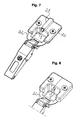
- FIG. 7 shows a perspective view of a double-link hinge in which the fastening flange 20 of the hinge cup is provided in its center plane with a housing-like part 21 in which a damping device of the type according to the invention is held in such a way that its plunger 3 engages in the cup-shaped recess protrudes.
- Figure 8 differs from that of Figure 7 only in that the hinge cup is divided in its longitudinal center plane and the halves formed thereby are assembled in such a way that the cylinder of the damping device can be composed of facing recesses of both split halves.
- the plunger 3 of the damping device projects back into the cup-shaped recess in such a way that the outer arm 22 meets this and undergoes a great braking force when closing.
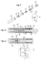
- the embodiment of the damping device according to the invention shown in Figures 9 to 11 consists of a hollow body in the form of a cylinder 50.
- a cylinder 50 In the cylinder 50 is provided with a through hole piston 51 axially displaceable and freely rotatably guided.
- the tubular piston 51 is provided on its inner wall with an internal thread 52.
- the cylinder 50 is closed at its right open side by a socket 53 which is supported with a flange 54 on the edge of the cylinder and rotatably connected thereto by known means and immovably connected in the axial direction.
- a plunger 55 is axially displaceable, but guided non-rotatably. The plunger projects beyond the flange 54 substantially around its impressible in the cylinder impact force length.
- the plunger Following its cylinder-projecting section, the plunger has cams 56 on opposite sides which, in the pushed-out state of the plunger 55 shown in FIG. 15, are supported on an annular step of the bush 53, which is formed by edge sections of the bushing 53 drawn inwards are.
- the sleeve 53 is at its in the cylinder 50 cross-tubular portion with opposite axially extending Provide grooves in which the cam 56, which form a rotation, are guided.
- the cams 56 are shown in the circled detail A in Figure 9 in enlarged form.
- the plunger 55 is provided with a portion 57 which carries a helical threaded ridge 58 with a pitch greater than that at which self-locking occurs.
- the provided with the thread 58 portion 57 of the plunger 55 is screwed into the internal thread 52 of the tubular piston 51 when it is pressed into the cylinder 55.
- a pin 60 is cut free.
- the pipe section 61 has, following the end face of the pin 60 on a widened portion 62 which forms inner and outer ring stages with which this widened portion 62 is supported on annular stages, on both sides of the groove between this and the inner cylinder wall on the one hand and on the other this and the end face of the pin 60 are formed.
- the facing annular end faces of the widened portion 62 of the pipe section 61 and the tubular piston 51 are provided with sawtooth teeth 63, 64, which are shown enlarged in the circled detail B of Figure 11.
- the teeth 63, 64 have flanks 65 extending in the axial direction and obliquely extending flanks 66.
- a compression spring 69 is clamped between the end face 67 of the pin 60 and the diameter-tapered end 68 of the plunger 55. This compression spring 29 strives to push the plunger 55 from its depressed position shown in FIG. 11 to its extended position shown in FIG.
- the pipe section 61 is held in the annular groove in the bottom region of the cylinder 50 by a high-viscosity grease, which may also have adhesive components to increase its toughness, so that it opposes increased resistance to its rotation.
- the cylinder 50 projecting portion of the plunger 55 If the cylinder 50 projecting portion of the plunger 55 is acted upon by a shock or pressure, it pushes the annular piston 51, in which the plunger is already screwed, against the front side of the widened tubular portion 62, so that the teeth 63, 64 engage each other in the manner of a dog clutch. As soon as the tubular piston 51 abuts against the tubular part 61, 62, it is offset by further pushing in the plunger 55 by sliding the inner and outer thread legs on each other in a left-hand rotation, so that the tubular piston 51 with the tubular portion 61, 62 in a coupled connection arrives.
- the tubular portion 61, 62 can be rotated only against an increased frictional resistance, it exerts on the further pressing of the plunger 55 in the cylinder 50 to this a strong damping effect. If the impact and a force acting on the plunger 55 pressure is completed, the compression spring 59 pushes the plunger under screwing back rotation of the tubular piston 51 back to its apparent from Figure 10 starting position.
Description
- Die Erfindung betrifft eine Dämpfungsvorrichtung für bewegliche Möbelteile, beispielsweise für Türen oder Schubladen, bestehend aus einem in einem Hohlkörper, z. B. einem Zylinder, gleitend geführten Kolben oder Stößel, der durch Federkraft in seine ausgeschobene Stellung beaufschlagt ist.
- Vorrichtungen dieser Art dienen dazu, bewegliche Möbelteile, beispielsweise Türen, Klappen oder Schubladen, beim schwungvollen Bewegen in ihre Schließstellung abzubremsen, um Geräusche beim Anstoßen an Korpusteile von Möbeln oder festen Teilen und Stoßbeanspruchungen zu verringern. Bei bekannten Vorrichtungen dieser Art werden die der Dämpfung oder dem Abbremsen der Möbelteile dienenden Dämpfungseinrichtungen nur über einen verhältnismäßig kleinen Weg im Schließbereich der beweglichen Möbelteile beaufschlagt, so dass sie nur eine entsprechend geringe Dämpfung oder Abbremsung zu bewirken vermögen.
- In den älteren, aber nicht vorveröffentlichten Gebrauchsmustern 20 302 524.4 und 20 303 534.8 sind Vorrichtungen zur Dämpfung der Bewegung beweglicher Möbelteile beschrieben, bei denen zur Erreichung einer starken Abbremsung und Dämpfung der Möbelteile deren verhältnismäßig kleine Schließbewegung über mindestens zweistufige Getriebemittel mit einem Übersetzungsverhältnis ins Schnelle auf einen Rotationsdämpfer oder den Kolben eines Dämpfungszylinders übertragen wird. Diese Dämpfungsvorrichtungen sind wegen der notwendigen zweistufigen Getriebemittel verhältnismäßig aufwendig.
- Aus DE-56719 C ist dabei ein Türschlagdämpfer bekannt, bei dem ein als Gewindestange ausgeführter Stößel so in einem Hohlkörper angebracht ist, dass er von einer Feder nach vorne gedrückt wird und sich in einem an der Vorderseite des Hohlkörpers angeordneten Innengewinde abstützt, so dass eine zufallende Tür durch die Reibung zwischen den Gewinden abgebremst wird.
- Aufgabe der Erfindung ist es daher, eine kostengünstig herstellbare Dämpfungsvorrichtung zu schaffen, die über die Wirkung der Gewindestange hinaus auch bei einem kurzen Hub des Stößels oder Kolbens eine große Bremswirkung gewährleistet.
- Erfindungsgemäß wird diese Aufgabe bei einer Dämpfungsvorrichtung der eingangs angegebenen Art dadurch gelöst, dass der Hohlkörper mit mindestens einem Abschnitt eines wendelförmigen Innengewindestegs und/oder der Kolben oder Stößel mit mindestens einem Abschnitt eines wendelförmigen Außengewindestegs versehen sind, dass sich die Gewindestege gleitend aufeinander oder jeweils Nokken oder Zapfen des Hohlkörpers oder des Kolbens oder Stößels auf einem Gewindeabschnitt des anderen Teils abstützen und dass die Steigung der Gewindestege größer ist als die, bei der Selbsthemmung eintritt. Die erfindungsgemäße Dämpfungsvorrichtung gewährleistet dadurch mit einer sehr kurzen axialen Bewegung des Kolbens oder Stößels eine sehr große Bremskraft, dass der axialen Bewegung eine Drehbewegung überlagert ist, so dass durch die reibend aufeinander mit einer wendelförmigen oder spiraligen Bewegung gleitenden Teile in axialer Richtung eine sehr hohe Bremskraft erreicht wird.
- Zweckmäßiger Weise ist eine Druckfeder zwischen dem Boden des Zylinders und dem Stößel oder Kolben eingespannt. Die Kraft der Druckfeder ist so bemessen, dass sie bei entlastetem Stößel oder Kolben diese in ihre ausgefahrene Stellung zu verschieben vermag.
- Zwischen der Druckfeder und dem Stößel oder Kolben kann ein Zwischenstück angeordnet sein, das undrehbar mit der Druckfeder verbunden ist. Dieses Zwischenstück kann eine aufgeraute Stirnfläche aufweisen, die sich die Reibungskraft erhöhend auf dem Stößel oder dem Kolben abstützt. Das andere Ende der Druckfeder kann undrehbar an einem den Boden des Zylinders bildenden Deckel gehaltert sein.
- In weiterer Ausgestaltung der Erfindung ist vorgesehen, dass der Stößel mit einem Abschnitt drehbar in eine Bohrung eines Kolbens greift, der mit mindestens einem Gewindeabschnitt oder Zapfen versehen ist.
- Ist es erwünscht, dass der aus dem Zylinder austretende Zapfen des Stößels nur eine Bewegung in axialer Richtung ausführt, der keine Drehbewegung überlagert ist, kann der Stößel einen unrunden, mehreckigen oder mit Nuten oder Längskeilen versehen Querschnitt aufweisen und einen Rand oder Deckel des Zylinders mit komplementärem Querschnitt durchsetzen.
- Nach einer anderen Ausführungsform wird die gestellte Aufgabe bei einer Dämpfungsvorrichtung nach dem Oberbegriff des Anspruchs 1 dadurch gelöst, dass der Kolben mit einer axialen Bohrung und mit mindestens einem Abschnitt eines wendelförmigen Innengewindestegs und der Stößel mit mindestens einem Abschnitt eines wendelförmigen Außengewindestegs versehen sind, dass der Kolben oder der Stößel axial verschieblich und drehbar und der andere Teil axial verschieblich und undrehbar in dem Hohlkörper geführt sind, dass der drehbar geführte Kolben oder Stößel mit Kupplungseinrichtungen versehen sind, die mit Gegenkupplungseinrichtungen eines in dem Hohlkörper gegen Widerstand verdrehbaren Elements in der vorgeschobenen Stellung des drehbaren Kolben oder Stößels kuppelbar sind, und dass die Steigung der Gewindestege größer ist als die, bei der Selbsthemmung eintritt.
- Diese Ausführungsform der erfindungsgemäßen Dämpfungsvorrichtung ermöglicht zusätzlich zu der relativen Drehung des Kolbens zu dem in diesen eingeschraubten Stößel und der Axialverschiebung beider in dem Hohlkörper eine starke Bremswirkung auf kurzem Wege dadurch, dass das verdrehbare Element ein starkes bremsendes Gegenmoment auf den mit diesem gekuppeltem Kolben oder Stößel ausübt. Die Dämpfungsvorrichtung kann so ausgeführt sein, dass der undrehbare Teil, also entweder der in dem Hohlkörper axial verschieblich aber undrehbar geführte Kolben oder Stößel, aus dem Hohlkörper soweit herausgeführt ist, das er unter Eindrücken in den Hohlkörper den Stoß des zu bremsenden Teils aufnimmt.
- Zweckmäßiger Weise ist der in den Kolben einschraubbare Stößel mit mindestens einem radialen Nocken oder einer Feder versehen, der oder die in einer Längsnut der Innenwand des Hohlkörpers oder einer diesen abschließenden Buchse geführt ist.
- Der Stößel oder der Kolben kann auch dadurch undrehbar in dem Hohlkörper geführt sein, das er mit einer unrunden äußeren Kontur versehen ist, die durch einen komplementären Abschnitt des Hohlkörpers undrehbar gehalten ist.
- In weiterer Ausgestaltung der Erfindung ist vorgesehen, dass das gegen ein bremsendes Drehmoment verdrehbare Element aus einem rohrförmigen Abschnitt besteht, der in einer Ringnut im Bodenbereich des Hohlkörpers drehbar gehalten ist. Der drehbare Abschnitt kann zusätzlich durch ein Fett hoher Viskosität in der Ringnut eingebettet sein. Dieses Fett erhöht die Reibung bzw. den Drehwiederstand des rohrförmigen Abschnitts. Zur Erhöhung der bremsenden Eigenschaften des Fetts hoher Viskosität können diesem klebende Bestandteile zugesetzt sein.
- Zweckmäßiger Weise bestehen die Kupplungs- und Gegenkupplungseinrichtungen aus auf den ringförmigen Stirnseiten des rohrförmigen Abschnitts und des rohrförmigen Kolbens angeordneten sägezahnförmigen Zähnen, die beim Eindrücken des Stößels in kuppelndem Eingriff miteinander kommen. Diese sägezahnförmigen Zähne weisen im kuppelnden Eingriff zur Mitnahme des rohrförmigen Abschnitts etwa in axialer Richtung des Stößels verlaufende Flanken auf. Die anderen Flanken der sägezahnförmigen Zähne sind abgeschrägt, so dass durch Federkraft die im Eingriff befindlichen Teile wieder auseinander geschoben werden können, ohne dass das bremsende, verdrehbare Element die Trennung und das Ausschieben verhindert.
- Zweckmäßiger Weise ist eine Druckfeder zwischen der Stirnseite des durch die Ringnut freigelegten Zapfens am Grund des Hohlkörpers und dem hinteren Ende des Stößels eingespannt.
- Ausführungsbeispiele der Erfindung werden nachstehend an Hand der Zeichnung näher erläutert. In dieser zeigt
- Figur 1:
- eine perspektivische Ansicht der erfindungsgemäßen Dämpfungsvorrichtung, die in einem Adaptergehäuse an einer Ecke eines Schranks gehaltert ist,
- Figur 2:
- eine perspektivische Ansicht der auseinander gezogenen Einzelteile einer ersten Ausführungsform der erfindungsgemäßen Dämpfungsvorrichtung,
- Figur 3:
- einen Längsschnitt durch die Dämpfungsvorrichtung nach Figur 2 im montierten Zustand,
- Figur 4:
- eine perspektivische Darstellung der auseinander gezogenen Einzelteile einer zweiten Ausführungsform der erfindungsgemäßen Dämpfungsvorrichtung,
- Figur 5:
- einen Längsschnitt durch die Dämpfungsvorrichtung nach Figur 4 im montierten Zustand,
- Figur 6:
- einen Längsschnitt durch eine dritte Ausführungsform der erfindungsgemäßen Dämpfungsvorrichtung,
- Fig. 7 u. 8:
- perspektivische Ansichten eines Doppellenkerscharniers, in deren Scharniertopf Dämpfungsvorrichtungen der erfindungsgemäßen Art integriert sind,
- Figur 9:
- eine weitere Ausführungsform der erfindungsgemäßen Dämpfungsvorrichtung im auseinander gezogenen Zustand seiner Einzelteile und mit einer eingekreisten vergrößerten Darstellung A einer Einzelheit,
- Figur 10:
- einen Längsschnitt durch die montierte Dämpfungsvorrichtung nach Figur 14 im ausgeschobenen Zustand seines Stößels und
- Figur 11:
- eine der Figur 10 entsprechenden Darstellung im eingedrückten Zustand des Stößels und mit einer vergrößert dargestellten eingekreisten Einzelheit B.
- Aus Figur 1 ist die obere linke Ecke eines Schranks ersichtlich, in der an der Innenseite einer Seitenwand 1 in einem Adaptergehäuse 2, das an der Seitenwand befestigt ist, eine Dämpfungsvorrichtung gehaltert ist, deren Stößel 3 die Stirnseite der Seitenwand 1 in der Weise überragt, dass der Schlag einer auf dieses treffenden Tür gedämpft wird.
- Eine erste Ausführungsform der erfindungsgemäßen Dämpfungsvorrichtung ist aus den Figuren 2 und 3 ersichtlich. Diese besteht aus einem Zylinder 4, der an seiner offenen Seite mit einem Innengewinde 5 versehen ist. In dieses Innengewinde ist mit Spiel das Außengewinde 6 des Stößels 3 eingeschraubt. Der rechte Teil des Zylinders 4 ist in der dargestellten Weise glattwandig ohne Innengewinde ausgeführt. Der Zylinder 4 ist durch einen Deckel 7 geschlossen. Zwischen dem Deckel 7 und dem Stößel 3 ist eine Druckfeder 8 eingespannt. Der Stößel weist zwischen seinem Gewindeabschnitt 6 und seinem runden, glattwandigen aus dem Zylinder austretenden Abschnitt 3 eine Stufe 9 auf, mit der er sich auf eine Stufe 10 abstützt, die durch den nach innen hin eingezogenen Rand des Zylinders 4 gebildet ist.
- Das Ausführungsbeispiel nach den Figuren 4 und 5 unterscheidet sich von dem nach den Figuren 2 und 3 im wesentlichen nur dadurch, dass das stößelseitige Ende der Feder 8 undrehbar an einem im Durchmesser verjüngten Abschnitt eines Bolzens 11 gehaltert ist, der sich mit seinem im Durchmesser verdickten Abschnitt auf dem Stößel 3 abstützt. Die Stirnfläche des verdickten Endteils des Bolzens 11 kann aufgeraut sein, so dass sich diese mit erhöhter Reibung auf der ebenen Stirnfläche des Stößels 3 abstützt. Der den Zylinder 4 schließende Deckel ist an seiner inneren Seite mit einer Stufe 12 versehen, an der sich das äußere Ende der Feder 8 undrehbar abstützt.
- Bei dem Ausführungsbeispiel nach Figur 6 sind der Stößel 13 und das mit einem Außengewinde versehene kolbenförmige Teil 14 voneinander getrennt. Das kolbenförmige Teil 14 besteht aus einem mit einem Außengewinde versehenen Bolzen, das mit einer Sacklochbohrung versehen ist. In diese Sacklochbohrung greift mit Spiel ein Zapfen 15 des Stößels 13 ein, so dass der kolbenförmige Bolzen 14 relativ zu dem Stößel 13 drehbar ist. Der Stößel 13 ist mit einem Bund 16 versehen, auf dessen innerer Ringstufe sich die ringförmige Stirnseite des kolbenartigen Bolzens 13 abstützt. Die äußere Ringstufe des Bundes 16 liegt im ausgefahrenen Zustand des Stößels an einer Ringstufe des Rands des Zylinders 4 an. Der an die Ringstufe 16 anschließende Teil des Stößels 13 ist unrund ausgeführt, wobei auch die Austrittsöffnung aus dem Zylinder 4 komplementär unrund ausgeführt ist, so dass der Stößel 13 axialverschieblich aber undrehbar an dem Zylinder 4 gehaltert ist. Auf die äußere Stoßfläche des Stößels 13 ist eine Kappe 17 aus elastomerem Material aufgesetzt.
- Aus Figur 7 ist eine perspektivische Darstellung eines Doppellenkerscharniers ersichtlich, bei dem der Befestigungsflansch 20 des Scharniertopfs in seiner Mittelebene mit einem gehäuseartigen Teil 21 versehen ist, in dem eine Dämpfungsvorrichtung der erfindungsgemäßen Art in der Weise gehaltert ist, dass deren Stößel 3 in die topfförmige Ausnehmung ragt. Beim Schließen des Scharniers stößt der äußere Lenker 22 des Doppellenkerscharniers auf den Stößel 3, so dass er mit großer Bremskraft auf kurzem Weg gedämpft wird.
- Die Ausführungsform nach Figur 8 unterscheidet sich von der nach Figur 7 nur dadurch, dass der Scharniertopf in seiner Längsmittelebene geteilt und die dadurch gebildeten Hälften in der Weise zusammengesetzt sind, dass sich der Zylinder der Dämpfungsvorrichtung aus zugewandten Ausnehmungen beider geteilten Hälften zusammensetzen lässt. Der Stößel 3 der Dämpfungsvorrichtung ragt wieder in die topfartige Ausnehmung in der Weise, dass der äußere Lenker 22 auf diesen trifft und beim Schließen eine große Bremskraft erfährt.
- Die in den Figuren 9 bis 11 dargestellte Ausführungsform der erfindungsgemäßen Dämpfungsvorrichtung besteht aus einem Hohlkörper in Form eines Zylinders 50. In dem Zylinder 50 ist ein mit einer Durchgangsbohrung versehener Kolben 51 axial verschieblich und frei drehbar geführt. Der rohrförmige Kolben 51 ist an seiner Innenwandung mit einem Innengewinde 52 versehen. Der Zylinder 50 ist an seiner rechten offenen Seite durch eine Buchse 53 geschlossen, die sich mit einem Flansch 54 auf dem Rand des Zylinders abstützt und mit diesem durch bekannte Mittel drehfest und in axialer Richtung unverschieblich verbunden ist. In der Buchse 53 ist ein Stößel 55 axial verschieblich, aber undrehbar geführt. Der Stößel überragt den Flansch 54 im wesentlichen um seine in den Zylinder unter Stoßwirkung eindrückbaren Länge. Der Stößel weist im Anschluss an seinen den Zylinder überragenden Abschnitt auf gegenüberliegenden Seiten Nocken 56 auf, die sich in dem aus Figur 15 ersichtlichen ausgeschobenen Zustand des Stößels 55 auf einer Ringstufe der Buchse 53 abstützen, die durch nach innen hin eingezogene Randabschnitte der Buchse 53 gebildet sind. Die Buchse 53 ist an ihrem in den Zylinder 50 greifenden rohrförmigen Abschnitt mit gegenüberliegenden axial verlaufenden Nuten versehen, in denen die Nocken 56, die eine Drehsicherung bilden, geführt sind. Die Nocken 56 sind in der eingekreisten Einzelheit A in Figur 9 in vergrößerter Form dargestellt. Im Anschluss an die Nocken 56 ist der Stößel 55 mit einem Abschnitt 57 versehen, der einen wendelförmig verlaufenden Gewindesteg 58 mit einer Steigung trägt, die größer ist als die, bei der Selbsthemmung eintritt. Der mit dem Gewinde 58 versehene Abschnitt 57 des Stößels 55 ist bei dessen Eindrücken in den Zylinder 55 in das Innengewinde 52 des rohrförmigen Kolbens 51 einschraubbar.
- Durch eine Ringnut im Bodenbereich des Zylinders 50 ist ein Zapfen 60 freigeschnitten. In die Ringnut ist mit Spiel ein Rohrstück 61 eingesetzt. Das Rohrstück 61 weist im Anschluss an die Stirnseite des Zapfens 60 einen verbreiterten Abschnitt 62 auf, der innere und äußere Ringstufen bildet, mit denen sich dieser verbreiterte Abschnitt 62 auf Ringstufen abstützt, die beidseits der Nut zwischen dieser und der inneren Zylinderwandung einerseits und andererseits zwischen dieser und der Stirnseite des Zapfens 60 gebildet sind.
- Die einander zugewandten ringförmigen Stirnseiten des verbreiterten Abschnitts 62 des Rohrstücks 61 und des rohrförmigen Kolbens 51 sind mit sägezahnförmigen Zähnen 63, 64 versehen, die in der eingekreisten Einzelheit B der Figur 11 vergrößert dargestellt sind. Die Zähne 63, 64 weisen in axialer Richtung verlaufende Flanken 65 und schräg verlaufende Flanken 66 auf. Zwischen der Stirnseite 67 des Zapfens 60 und dem im Durchmesser verjüngten Ende 68 des Stößels 55 ist eine Druckfeder 69 eingespannt. Diese Druckfeder 29 ist bestrebt, den Stößel 55 aus seiner aus Figur 11 ersichtlichen eingedrückten Stellung seine aus Figur 10 ersichtliche ausgeschobene Stellung zu drücken.
- Das Rohrstück 61 ist durch ein Fett hoher Viskosität, das auch zur Erhöhung seiner Zähigkeit klebende Bestandteile aufweisen kann, in der Ringnut im Bodenbereich des Zylinders 50 gehalten, so dass es seiner Verdrehung einen erhöhten Widerstand entgegensetzt.
- Wird der den Zylinder 50 überragende Abschnitt des Stößels 55 durch einen Stoß oder Druck beaufschlagt, schiebt er auf kurzem Wege den ringförmigen Kolben 51, in den der Stößel bereits eingeschraubt ist, gegen die Stirnseite des verbreiterten rohrförmigen Abschnitts 62, so dass die Zähne 63, 64 nach Art einer Klauenkupplung miteinander in Eingriff kommen. Sobald der rohrförmige Kolben 51 gegen das rohrförmige Teil 61, 62 stößt, wird er durch weiteres Eindrücken des Stößels 55 durch Abgleiten der Innen- und Außengewindestege aufeinander in eine Linksdrehung versetzt, so dass der rohrförmige Kolben 51 mit dem rohrförmigen Abschnitt 61, 62 in eine gekuppelte Verbindung gelangt. Da sich der rohrförmige Abschnitt 61, 62 nur gegen einen erhöhten Reibungswiderstand drehen lässt, übt er beim weiteren Eindrücken des Stößels 55 in den Zylinder 50 auf diesen eine stark dämpfende Wirkung aus. Ist die Stoßwirkung und ein auf den Stößel 55 wirkender Druck beendet, schiebt die Druckfeder 59 den Stößel unter schraubender Rückdrehung des rohrförmigen Kolbens 51 wieder in seine aus Figur 10 ersichtliche Ausgangsstellung.
Claims (12)
- Dämpfungsvorrichtung für bewegliche Möbelteile, beispielsweise für Türen oder Schubladen, bestehend aus einem in einen Hohlkörper, z. B. einem Zylinder, gleitend geführten Stößel, der durch Federkraft in seine ausgeschobene Stellung beaufschlagt ist,
wobei der Hohlkörper (4) mit mindestens einem Abschnitt eines wendelförmigen Innengewindestegs (5) und der Stößel (3) mit mindestens einem Abschnitt eines wendelförmigen Außengewindestegs (6) versehen sind,
wobei sich die Gewindestege (5, 6) gleitend aufeinander abstützen und
wobei die Steigung der Gewindestege größer ist als die, bei der Selbsthemmung eintritt,
dadurch gekennzeichnet,
dass zwischen der Druckfeder (8) und dem Stößel (3) ein Zwischenstück (11) angeordnet ist, das undrehbar mit der Druckfeder (8) verbunden ist. - Dämpfungsvorrichtung nach Anspruch 1, dadurch gekennzeichnet, dass die Druckfeder (8) zwischen dem Boden (7) des Zylinders (4) und dem Stößel (3) oder Kolben (14) eingespannt ist.
- Dämpfungsvorrichtung nach Anspruch 1, dadurch gekennzeichnet, dass sich das Zwischenstück (11) mit aufgerauter Stirnfläche auf den Stößel (3) oder Kolben abstützt.
- Dämpfungsvorrichtung nach einem der Ansprüche 1 bis 3, dadurch gekennzeichnet, dass die Druckfeder (8) undrehbar an einem den Boden des Zylinders bildenden Deckel (7) gehaltert ist.
- Dämpfungsvorrichtung für bewegliche Möbelteile, beispielsweise für Türen oder Schubladen, bestehend aus einem in einen Hohlkörper, z. B. einem Zylinder, gleitend geführten Kolben, der durch Federkraft in seine ausgeschobene Stellung beaufschlagt ist,
wobei der Hohlkörper (4) mit mindestens einem Abschnitt eines wendelförmigen Innengewindestegs (5) und der Kolben (14) mit mindestens einem Abschnitt eines wendelförmigen Außengewindestegs (6) versehen sind,
wobei sich die Gewindestege (5, 6) gleitend aufeinander abstützen und
wobei die Steigung der Gewindestege größer ist als die, bei der Selbsthemmung eintritt,
dadurch gekennzeichnet,
dass ein Stößel (3) mit einem Abschnitt (15) drehbar in eine Bohrung des Kolbens (14) greift. - Dämpfungsvorrichtung nach Anspruch 5, dadurch gekennzeichnet, dass der aus dem Zylinder (4) austretende Zapfen des Stößels (13) einen unrunden, mehreckigen oder mit Nuten oder Längskeilen versehenen Querschnitt aufweist und einen Rand oder Deckel des Zylinders (4) mit komplementärem Durchbruch durchsetzt.
- Dämpfungsvorrichtung für bewegliche Möbelteile, beispielsweise für Türen oder Schubladen, bestehend aus einem in einen Hohlkörper, z. B. einem Zylinder (50) gleitend geführten Kolben, der durch Federkraft in seine ausgeschobene Stellung beaufschlagt ist,
dadurch gekennzeichnet,
dass der Kolben (51) mit einer axialen Bohrung und mit mindestens einem Abschnitt eines wendelförmigen Innengewindestegs (52) und ein in den Kolben (51) eingeschraubter Stößel (55) mit mindestens einem Abschnitt eines wendelförmigen Außenstegs (58) versehen sind,
dass sich die Gewindestege (52, 58) gleitend aufeinander oder jeweils Nokken oder Zapfen des Kolbens oder des Stößels auf einem Gewindeabschnitt des anderen Teils abstützen,
dass der Kolben (51) oder der Stößel (55) axial verschieblich und drehbar und der andere Teil axial verschieblich und undrehbar in dem Hohlkörper (50) geführt sind,
dass der drehbar geführte Kolben (51) oder Stößel mit Kupplungseinrichtungen (64) versehen sind, die mit Gegenkupplungseinrichtungen (63) eines in dem Hohlkörper (50) gegen Widerstand verdrehbaren Elements (61) in der vorgeschobenen Stellung des drehbaren Kolbens oder Stößels kuppelbar sind, und
dass die Steigung der Gewindestege größer ist als die, bei der Selbsthemmung eintritt. - Dämpfungsvorrichtung nach Anspruch 7 dadurch gekennzeichnet, dass der in den Kolben (51) einschraubbare Stößel (55) mit mindestens einem radialen Nocken (56) oder einer Feder versehen ist, der oder die in einer Längsnut in der Innenwand des Hohlkörpers (50) oder einer diesen abschließenden Buchse (53) geführt sind.
- Dämpfungsvorrichtung nach Anspruch 7 oder 8, dadurch gekennzeichnet, dass das gegen ein bremsendes Drehmoment verdrehbare Element aus einem rohrförmigen Abschnitt (61) besteht, der in einer Ringnut im Bodenbereich des Hohlkörpers (50) drehbar gehalten ist.
- Dämpfungsvorrichtung nach Anspruch 9, dadurch gekennzeichnet, dass der rohrförmige Abschnitt (61) durch ein Fett hoher Viskosität in der Ringnut eingebettet ist.
- Dämpfungsvorrichtung nach Anspruch 9 oder 10, dadurch gekennzeichnet, dass die Kupplungs- und Gegenkupplungseinrichtungen aus auf den ringförmigen Stirnseiten des ringförmigen Abschnitts und des rohrförmigen Kolbens angeordneten sägezahnförmigen Zähnen (63, 64) bestehen, die beim Eindrücken des Stößels in ihren kupplenden Eingriff miteinander geraten.
- Dämpfungsvorrichtung nach einem der Ansprüche 7 bis 11, dadurch gekennzeichnet, dass eine Druckfeder (69) zwischen der Stirnseite des durch die Ringnut freigelegten Zapfens (60) am Grund des Hohlkörpers (50) und dem hinteren Ende des Stößels (55) eingespannt ist.
Priority Applications (1)
| Application Number | Priority Date | Filing Date | Title |
|---|---|---|---|
| SI200430214T SI1469153T1 (sl) | 2003-04-14 | 2004-03-17 | Blaĺ˝ilec udarcev za vrata s spiralnim gibanjem |
Applications Claiming Priority (4)
| Application Number | Priority Date | Filing Date | Title |
|---|---|---|---|
| DE20305992U DE20305992U1 (de) | 2003-04-14 | 2003-04-14 | Dämpfungsvorrichtung für bewegliche Möbelteile |
| DE20305992U | 2003-04-14 | ||
| DE20309874U DE20309874U1 (de) | 2003-06-26 | 2003-06-26 | Dämpfer mit spiralförmiger Bewegung |
| DE20309874U | 2003-06-26 |
Publications (2)
| Publication Number | Publication Date |
|---|---|
| EP1469153A1 EP1469153A1 (de) | 2004-10-20 |
| EP1469153B1 true EP1469153B1 (de) | 2007-01-24 |
Family
ID=32909795
Family Applications (1)
| Application Number | Title | Priority Date | Filing Date |
|---|---|---|---|
| EP04006441A Expired - Lifetime EP1469153B1 (de) | 2003-04-14 | 2004-03-17 | Türschlagdämpfer mit spiralförmiger Bewegung |
Country Status (12)
| Country | Link |
|---|---|
| US (1) | US7234569B2 (de) |
| EP (1) | EP1469153B1 (de) |
| JP (1) | JP2004316912A (de) |
| KR (1) | KR20040089495A (de) |
| CN (1) | CN100464051C (de) |
| AT (1) | ATE352693T1 (de) |
| BR (1) | BRPI0401111A (de) |
| DE (1) | DE502004002724D1 (de) |
| ES (1) | ES2279245T3 (de) |
| PL (1) | PL366354A1 (de) |
| SI (1) | SI1469153T1 (de) |
| TW (1) | TW200500545A (de) |
Cited By (1)
| Publication number | Priority date | Publication date | Assignee | Title |
|---|---|---|---|---|
| DE102009007416A1 (de) | 2009-02-04 | 2010-08-05 | Lautenschläger, Horst | Dämpfungseinrichtung für Möbeltüren |
Families Citing this family (45)
| Publication number | Priority date | Publication date | Assignee | Title |
|---|---|---|---|---|
| DE20115250U1 (de) | 2001-07-06 | 2002-11-14 | Lautenschlaeger Mepla Werke | Dämpfungsvorrichtung |
| DE202004019395U1 (de) * | 2003-12-02 | 2005-04-14 | Karl Simon Gmbh & Co. Kg | Anschlagdämpfer |
| US8118285B2 (en) * | 2004-07-01 | 2012-02-21 | Avm Industries | Gas spring with integrated lead screw drive |
| DE202004016396U1 (de) * | 2004-10-21 | 2005-01-05 | Julius Blum Gmbh | Dämpferanordnung |
| AT502943B1 (de) * | 2005-04-01 | 2011-07-15 | Blum Gmbh Julius | Dämpfvorrichtung für bewegbare möbelteile |
| DE202005012310U1 (de) * | 2005-07-22 | 2006-11-23 | Hettich-Oni Gmbh & Co. Kg | Dämpfungseinrichtung |
| CN101007298B (zh) * | 2006-01-24 | 2011-06-29 | 深圳富泰宏精密工业有限公司 | 支架稳固装置 |
| KR101275560B1 (ko) * | 2006-09-05 | 2013-06-20 | 엘지전자 주식회사 | 냉장고 |
| FR2905997B1 (fr) * | 2006-09-14 | 2008-11-28 | Conseil Et Tech Sarl | Dispositif a friction pour le controle d'effort, et un amortisseur a friction comprenant un tel dispositif |
| KR101252165B1 (ko) * | 2006-09-21 | 2013-04-05 | 엘지전자 주식회사 | 냉장고 |
| DE202007018954U1 (de) * | 2007-03-01 | 2009-12-10 | Julius Blum Gmbh | Möbelscharnier |
| AT10097U1 (de) * | 2007-04-30 | 2008-09-15 | Blum Gmbh Julius | Federpuffer für ein möbel |
| DE102007047287A1 (de) * | 2007-05-03 | 2008-11-13 | Lautenschläger, Horst | Möbelscharnier mit einer Dämpfungsvorrichtung |
| JP5029248B2 (ja) * | 2007-09-21 | 2012-09-19 | オイレス工業株式会社 | 回転式摩擦ダンパ |
| US8505165B2 (en) * | 2008-01-22 | 2013-08-13 | Grass America, Inc. | Damping mechanism for cabinet hinge assembly |
| DE102008035926A1 (de) * | 2008-08-01 | 2010-02-18 | Suspa Holding Gmbh | Schrank mit Dämpfer |
| AT508068B1 (de) | 2009-03-25 | 2016-11-15 | Blum Gmbh Julius | Möbelscharnier |
| GB2469846B (en) * | 2009-04-29 | 2013-12-11 | Lama D D Dekani | Improvements in hinge assemblies |
| DE202009017319U1 (de) * | 2009-12-21 | 2011-05-05 | Grass Gmbh | Möbel und Vorrichtung für ein Möbel |
| US8517477B2 (en) | 2010-05-10 | 2013-08-27 | Hussmann Corporation | Door hold open mechanism for a merchandiser |
| CN102401055B (zh) * | 2010-09-10 | 2013-12-11 | 鸿富锦精密工业(深圳)有限公司 | 缓冲装置 |
| CN102116120A (zh) * | 2010-12-31 | 2011-07-06 | 费赟 | 移门缓冲器 |
| US8871034B2 (en) * | 2011-02-15 | 2014-10-28 | GM Global Technology Operations LLC | Production washing assembly verification system and method |
| DE202011103288U1 (de) * | 2011-06-30 | 2012-10-04 | Grass Gmbh | Dämpfungsvorrichtung, Möbelscharnier und Möbel |
| JP2012037060A (ja) * | 2011-11-21 | 2012-02-23 | Oiles Corp | 回転式摩擦ダンパ |
| AT15271U1 (de) * | 2012-02-16 | 2017-04-15 | Blum Gmbh Julius | Möbelscharnier |
| AT513962A1 (de) * | 2013-01-30 | 2014-08-15 | Julius Blum Ges | Möbelbeschlag |
| ITMI20131542A1 (it) * | 2013-09-19 | 2015-03-20 | Salice Arturo Spa | Cerniera decelerata per mobili |
| US20150090271A1 (en) * | 2013-10-01 | 2015-04-02 | Julian Cruzada | Impact force dampening of spring release |
| GB2520480B (en) | 2013-11-05 | 2020-08-12 | Titus D O O Dekani | Improvements in hinge assemblies |
| US9963917B2 (en) * | 2013-12-13 | 2018-05-08 | Ford Global Technologies, Llc | Hood stop assemblies for a vehicle and methods for setting a position of a vehicle hood |
| JP6170425B2 (ja) * | 2013-12-18 | 2017-07-26 | ニッタ株式会社 | 摩擦ダンパー |
| US9702176B2 (en) | 2014-07-07 | 2017-07-11 | Itt Manufacturing Enterprises Llc | Spring loaded actuator assembly |
| CN104675252A (zh) * | 2015-02-05 | 2015-06-03 | 客来福家居股份有限公司 | 一种外挂式移门阻尼器 |
| JP6526982B2 (ja) * | 2015-02-13 | 2019-06-05 | オイレス工業株式会社 | ダンパ |
| JP6400192B2 (ja) * | 2015-05-13 | 2018-10-03 | 株式会社パイオラックス | 緩衝装置 |
| CN106882021B (zh) * | 2017-03-22 | 2019-03-29 | 神龙汽车有限公司 | 可自动调节高度的缓冲块及其在汽车上的连接结构 |
| CN107686050A (zh) * | 2017-08-24 | 2018-02-13 | 芜湖市长江起重设备制造有限公司 | 一种新型桥式起重机油压防撞装置 |
| CN107724762A (zh) * | 2017-11-10 | 2018-02-23 | 智性科技南通有限公司 | 粘滞和摩擦耗能双功能阻尼器 |
| CN108922264B (zh) * | 2018-08-30 | 2020-10-02 | 安徽工程大学 | 英语学习机 |
| CN111691132B (zh) * | 2019-03-12 | 2023-02-17 | 青岛海尔洗衣机有限公司 | 减震器和衣物处理设备 |
| JP7131696B2 (ja) * | 2019-04-24 | 2022-09-06 | 村田機械株式会社 | 緩衝装置、スタッカクレーン、搬送システム及び緩衝装置用治具 |
| KR102281054B1 (ko) * | 2021-04-09 | 2021-07-23 | 대우공업 (주) | 차량 도어용 밀림 방지 장치 |
| US11920401B2 (en) | 2021-05-03 | 2024-03-05 | Kohler Co. | Slow close mechanism for sliding applications |
| JP7192157B1 (ja) * | 2022-05-31 | 2022-12-19 | 株式会社オリジン | ロータリーダンパー |
Family Cites Families (16)
| Publication number | Priority date | Publication date | Assignee | Title |
|---|---|---|---|---|
| DE33028C (de) | A. SCHWAN in Berlin C, Jüdenstr. 251 | Thürzuschlaghinderer | ||
| DE56719C (de) * | B. RENNECKE und G. JABUSCH in Magdeburg, Sieversthor 9 | Thürschlagdämpfer | ||
| AT5125B (de) | 1899-06-21 | 1901-09-10 | Hermenn Baumgarten | |
| US1025388A (en) * | 1910-12-03 | 1912-05-07 | Highland T Finnell | Shock-absorber for vehicles. |
| US1028850A (en) * | 1911-08-15 | 1912-06-11 | William H Aspegren | Door-check. |
| US1218197A (en) * | 1916-04-14 | 1917-03-06 | Eben H Mackinlay | Door-check. |
| US1654763A (en) * | 1925-12-10 | 1928-01-03 | Tauscher Henry | Shock absorber |
| AT207289B (de) | 1958-06-23 | 1960-01-25 | Friedrich Kostelnik | Einrichtung zum Abbremsen der Schließbewegung von um eine Achse drehbaren Türen od. dgl. |
| DE3401427C2 (de) * | 1984-01-17 | 1995-02-02 | Wilke Heinrich Hewi Gmbh | Türpuffer |
| ES295448Y (es) * | 1986-06-25 | 1987-09-01 | Zeljko Bebek Vuksic | Bisagra de resorte con amortiguador, perfeccionada |
| CN88201664U (zh) * | 1988-03-10 | 1988-11-23 | 朱湘章 | 用于门扇上的缓冲装置 |
| DE29913854U1 (de) * | 1999-08-09 | 1999-10-07 | Salice Arturo Spa | Bremsverzögerungsvorrichtung für Türen, Fenster o.dgl. |
| KR100403366B1 (ko) | 2001-01-17 | 2003-10-30 | 주식회사 솔텍 | 도어 개폐 완충 장치 |
| DE20205905U1 (de) * | 2002-04-16 | 2002-07-11 | Blum Gmbh Julius | Fluiddämpfer |
| DE20303534U1 (de) | 2002-11-13 | 2004-03-25 | Arturo Salice S.P.A., Novedrate | Scharnier |
| DE20302524U1 (de) | 2003-02-17 | 2004-06-24 | Arturo Salice S.P.A., Novedrate | Vorrichtung zur Dämpfung der Bewegung beweglicher Möbelteile in deren Schließbereich |
-
2004
- 2004-02-25 TW TW093104727A patent/TW200500545A/zh unknown
- 2004-03-17 AT AT04006441T patent/ATE352693T1/de not_active IP Right Cessation
- 2004-03-17 SI SI200430214T patent/SI1469153T1/sl unknown
- 2004-03-17 EP EP04006441A patent/EP1469153B1/de not_active Expired - Lifetime
- 2004-03-17 DE DE502004002724T patent/DE502004002724D1/de not_active Expired - Fee Related
- 2004-03-17 PL PL36635404A patent/PL366354A1/xx not_active Application Discontinuation
- 2004-03-17 ES ES04006441T patent/ES2279245T3/es not_active Expired - Lifetime
- 2004-04-06 JP JP2004112324A patent/JP2004316912A/ja active Pending
- 2004-04-08 KR KR1020040023973A patent/KR20040089495A/ko not_active IP Right Cessation
- 2004-04-13 BR BR0401111-2A patent/BRPI0401111A/pt not_active IP Right Cessation
- 2004-04-13 US US10/823,332 patent/US7234569B2/en not_active Expired - Fee Related
- 2004-04-14 CN CNB2004100329710A patent/CN100464051C/zh not_active Expired - Fee Related
Cited By (1)
| Publication number | Priority date | Publication date | Assignee | Title |
|---|---|---|---|---|
| DE102009007416A1 (de) | 2009-02-04 | 2010-08-05 | Lautenschläger, Horst | Dämpfungseinrichtung für Möbeltüren |
Also Published As
| Publication number | Publication date |
|---|---|
| CN100464051C (zh) | 2009-02-25 |
| KR20040089495A (ko) | 2004-10-21 |
| ES2279245T3 (es) | 2007-08-16 |
| US7234569B2 (en) | 2007-06-26 |
| DE502004002724D1 (de) | 2007-03-15 |
| TW200500545A (en) | 2005-01-01 |
| SI1469153T1 (sl) | 2007-06-30 |
| JP2004316912A (ja) | 2004-11-11 |
| EP1469153A1 (de) | 2004-10-20 |
| PL366354A1 (en) | 2004-10-18 |
| BRPI0401111A (pt) | 2005-02-09 |
| CN1542252A (zh) | 2004-11-03 |
| ATE352693T1 (de) | 2007-02-15 |
| US20040201154A1 (en) | 2004-10-14 |
Similar Documents
| Publication | Publication Date | Title |
|---|---|---|
| EP1469153B1 (de) | Türschlagdämpfer mit spiralförmiger Bewegung | |
| EP1319787B1 (de) | Luftdämpfer für bewegliche Möbelteile | |
| EP1076145B1 (de) | Bremsverzögerungsvorrichtung für Türen, Fenster o. dgl. | |
| EP1404938B2 (de) | Dämpfungsvorrichtung | |
| EP1907657B1 (de) | Dämpfungselement | |
| EP1006251A2 (de) | Bremsverzögerungsvorrichtung | |
| WO2012139954A1 (de) | Schliess-scharnier | |
| WO2009141044A1 (de) | Dämpfungseinrichtung für möbeltüren | |
| EP1344885A2 (de) | Möbelbeschlag mit Brems- und Dämpfungsvorrichtung | |
| EP2697465A1 (de) | Tür-anordnung | |
| DE102014212863A1 (de) | Antriebsanordnung und Klappensteuerung | |
| EP2807395B1 (de) | Vorrichtung zur dämpfung der bewegung eines beweglich gelagerten bauteils | |
| EP2078167B1 (de) | Dämpfungsvorrichtung mit einstellbar veränderlicher dämpfungscharakteristik zur dämpfung von beweglichen möbelteilen | |
| WO2016177559A1 (de) | Moebelscharnier mit einem dämpfer | |
| DE202013009699U1 (de) | Dämpfer für bewegbare Möbelteile | |
| AT512306A4 (de) | Vorrichtung zur dämpfung der bewegung eines beweglich gelagerten bauteils | |
| EP1304440A2 (de) | Bremsverzögerungsvorrichtung | |
| EP2620079B1 (de) | Einziehvorrichtung für mindestens zwei ausziehbare Möbelteile | |
| DE212011100150U1 (de) | Möbeldämpfer | |
| DE202011107194U1 (de) | Dämpfer für eine Drehbewegung von Toilettendeckeln und -brillen | |
| DE102005007742B3 (de) | Druckgasfeder | |
| DE202016102909U1 (de) | Möbelscharnier | |
| DE102006008525A1 (de) | Vorrichtung zum Befestigen einer Fahrzeugtür | |
| WO2009086922A1 (de) | Dämpfungsvorrichtung mit mehrstufig veränderlicher dämpfungscharakteristik, insbesondere zur dämpfung von beweglichen möbelteilen | |
| DE102014103558B3 (de) | Selbstschließendes Rollentürband |
Legal Events
| Date | Code | Title | Description |
|---|---|---|---|
| PUAI | Public reference made under article 153(3) epc to a published international application that has entered the european phase |
Free format text: ORIGINAL CODE: 0009012 |
|
| 17P | Request for examination filed |
Effective date: 20040414 |
|
| AK | Designated contracting states |
Kind code of ref document: A1 Designated state(s): AT BE BG CH CY CZ DE DK EE ES FI FR GB GR HU IE IT LI LU MC NL PL PT RO SE SI SK TR |
|
| AX | Request for extension of the european patent |
Extension state: AL LT LV MK |
|
| 17Q | First examination report despatched |
Effective date: 20041206 |
|
| AKX | Designation fees paid |
Designated state(s): AT BE BG CH CY CZ DE DK EE ES FI FR GB GR HU IE IT LI LU MC NL PL PT RO SE SI SK TR |
|
| GRAP | Despatch of communication of intention to grant a patent |
Free format text: ORIGINAL CODE: EPIDOSNIGR1 |
|
| GRAS | Grant fee paid |
Free format text: ORIGINAL CODE: EPIDOSNIGR3 |
|
| GRAA | (expected) grant |
Free format text: ORIGINAL CODE: 0009210 |
|
| AK | Designated contracting states |
Kind code of ref document: B1 Designated state(s): AT BE BG CH CY CZ DE DK EE ES FI FR GB GR HU IE IT LI LU MC NL PL PT RO SE SI SK TR |
|
| PG25 | Lapsed in a contracting state [announced via postgrant information from national office to epo] |
Ref country code: DK Free format text: LAPSE BECAUSE OF FAILURE TO SUBMIT A TRANSLATION OF THE DESCRIPTION OR TO PAY THE FEE WITHIN THE PRESCRIBED TIME-LIMIT Effective date: 20070124 Ref country code: IE Free format text: LAPSE BECAUSE OF FAILURE TO SUBMIT A TRANSLATION OF THE DESCRIPTION OR TO PAY THE FEE WITHIN THE PRESCRIBED TIME-LIMIT Effective date: 20070124 Ref country code: PL Free format text: LAPSE BECAUSE OF FAILURE TO SUBMIT A TRANSLATION OF THE DESCRIPTION OR TO PAY THE FEE WITHIN THE PRESCRIBED TIME-LIMIT Effective date: 20070124 Ref country code: NL Free format text: LAPSE BECAUSE OF FAILURE TO SUBMIT A TRANSLATION OF THE DESCRIPTION OR TO PAY THE FEE WITHIN THE PRESCRIBED TIME-LIMIT Effective date: 20070124 Ref country code: FI Free format text: LAPSE BECAUSE OF FAILURE TO SUBMIT A TRANSLATION OF THE DESCRIPTION OR TO PAY THE FEE WITHIN THE PRESCRIBED TIME-LIMIT Effective date: 20070124 |
|
| REG | Reference to a national code |
Ref country code: GB Ref legal event code: FG4D Free format text: NOT ENGLISH |
|
| REG | Reference to a national code |
Ref country code: CH Ref legal event code: EP |
|
| PGFP | Annual fee paid to national office [announced via postgrant information from national office to epo] |
Ref country code: SI Payment date: 20070220 Year of fee payment: 4 |
|
| REG | Reference to a national code |
Ref country code: IE Ref legal event code: FG4D Free format text: LANGUAGE OF EP DOCUMENT: GERMAN |
|
| REF | Corresponds to: |
Ref document number: 502004002724 Country of ref document: DE Date of ref document: 20070315 Kind code of ref document: P |
|
| PGFP | Annual fee paid to national office [announced via postgrant information from national office to epo] |
Ref country code: ES Payment date: 20070316 Year of fee payment: 4 |
|
| PGFP | Annual fee paid to national office [announced via postgrant information from national office to epo] |
Ref country code: AT Payment date: 20070323 Year of fee payment: 4 |
|
| PGFP | Annual fee paid to national office [announced via postgrant information from national office to epo] |
Ref country code: DE Payment date: 20070329 Year of fee payment: 4 |
|
| PG25 | Lapsed in a contracting state [announced via postgrant information from national office to epo] |
Ref country code: SE Free format text: LAPSE BECAUSE OF FAILURE TO SUBMIT A TRANSLATION OF THE DESCRIPTION OR TO PAY THE FEE WITHIN THE PRESCRIBED TIME-LIMIT Effective date: 20070424 |
|
| PG25 | Lapsed in a contracting state [announced via postgrant information from national office to epo] |
Ref country code: BG Free format text: LAPSE BECAUSE OF FAILURE TO SUBMIT A TRANSLATION OF THE DESCRIPTION OR TO PAY THE FEE WITHIN THE PRESCRIBED TIME-LIMIT Effective date: 20070425 |
|
| PG25 | Lapsed in a contracting state [announced via postgrant information from national office to epo] |
Ref country code: PT Free format text: LAPSE BECAUSE OF FAILURE TO SUBMIT A TRANSLATION OF THE DESCRIPTION OR TO PAY THE FEE WITHIN THE PRESCRIBED TIME-LIMIT Effective date: 20070625 |
|
| NLV1 | Nl: lapsed or annulled due to failure to fulfill the requirements of art. 29p and 29m of the patents act | ||
| REG | Reference to a national code |
Ref country code: ES Ref legal event code: FG2A Ref document number: 2279245 Country of ref document: ES Kind code of ref document: T3 |
|
| GBV | Gb: ep patent (uk) treated as always having been void in accordance with gb section 77(7)/1977 [no translation filed] |
Effective date: 20070124 |
|
| REG | Reference to a national code |
Ref country code: IE Ref legal event code: FD4D |
|
| EN | Fr: translation not filed | ||
| PG25 | Lapsed in a contracting state [announced via postgrant information from national office to epo] |
Ref country code: SK Free format text: LAPSE BECAUSE OF FAILURE TO SUBMIT A TRANSLATION OF THE DESCRIPTION OR TO PAY THE FEE WITHIN THE PRESCRIBED TIME-LIMIT Effective date: 20070124 Ref country code: GB Free format text: LAPSE BECAUSE OF FAILURE TO SUBMIT A TRANSLATION OF THE DESCRIPTION OR TO PAY THE FEE WITHIN THE PRESCRIBED TIME-LIMIT Effective date: 20070124 |
|
| PLBE | No opposition filed within time limit |
Free format text: ORIGINAL CODE: 0009261 |
|
| STAA | Information on the status of an ep patent application or granted ep patent |
Free format text: STATUS: NO OPPOSITION FILED WITHIN TIME LIMIT |
|
| BERE | Be: lapsed |
Owner name: ARTURO SALICE S.P.A. Effective date: 20070331 |
|
| 26N | No opposition filed |
Effective date: 20071025 |
|
| PG25 | Lapsed in a contracting state [announced via postgrant information from national office to epo] |
Ref country code: RO Free format text: LAPSE BECAUSE OF FAILURE TO SUBMIT A TRANSLATION OF THE DESCRIPTION OR TO PAY THE FEE WITHIN THE PRESCRIBED TIME-LIMIT Effective date: 20070124 Ref country code: CZ Free format text: LAPSE BECAUSE OF FAILURE TO SUBMIT A TRANSLATION OF THE DESCRIPTION OR TO PAY THE FEE WITHIN THE PRESCRIBED TIME-LIMIT Effective date: 20070124 Ref country code: BE Free format text: LAPSE BECAUSE OF NON-PAYMENT OF DUE FEES Effective date: 20070331 |
|
| PG25 | Lapsed in a contracting state [announced via postgrant information from national office to epo] |
Ref country code: MC Free format text: LAPSE BECAUSE OF NON-PAYMENT OF DUE FEES Effective date: 20070331 |
|
| PG25 | Lapsed in a contracting state [announced via postgrant information from national office to epo] |
Ref country code: FR Free format text: LAPSE BECAUSE OF FAILURE TO SUBMIT A TRANSLATION OF THE DESCRIPTION OR TO PAY THE FEE WITHIN THE PRESCRIBED TIME-LIMIT Effective date: 20070914 |
|
| REG | Reference to a national code |
Ref country code: CH Ref legal event code: PL |
|
| PG25 | Lapsed in a contracting state [announced via postgrant information from national office to epo] |
Ref country code: FR Free format text: LAPSE BECAUSE OF FAILURE TO SUBMIT A TRANSLATION OF THE DESCRIPTION OR TO PAY THE FEE WITHIN THE PRESCRIBED TIME-LIMIT Effective date: 20070124 Ref country code: AT Free format text: LAPSE BECAUSE OF NON-PAYMENT OF DUE FEES Effective date: 20080317 |
|
| PG25 | Lapsed in a contracting state [announced via postgrant information from national office to epo] |
Ref country code: CH Free format text: LAPSE BECAUSE OF NON-PAYMENT OF DUE FEES Effective date: 20080331 Ref country code: DE Free format text: LAPSE BECAUSE OF NON-PAYMENT OF DUE FEES Effective date: 20081001 Ref country code: LI Free format text: LAPSE BECAUSE OF NON-PAYMENT OF DUE FEES Effective date: 20080331 Ref country code: EE Free format text: LAPSE BECAUSE OF FAILURE TO SUBMIT A TRANSLATION OF THE DESCRIPTION OR TO PAY THE FEE WITHIN THE PRESCRIBED TIME-LIMIT Effective date: 20070124 |
|
| PG25 | Lapsed in a contracting state [announced via postgrant information from national office to epo] |
Ref country code: SI Free format text: LAPSE BECAUSE OF NON-PAYMENT OF DUE FEES Effective date: 20080318 |
|
| REG | Reference to a national code |
Ref country code: SI Ref legal event code: KO00 Effective date: 20081127 |
|
| REG | Reference to a national code |
Ref country code: ES Ref legal event code: FD2A Effective date: 20080318 |
|
| PG25 | Lapsed in a contracting state [announced via postgrant information from national office to epo] |
Ref country code: CY Free format text: LAPSE BECAUSE OF FAILURE TO SUBMIT A TRANSLATION OF THE DESCRIPTION OR TO PAY THE FEE WITHIN THE PRESCRIBED TIME-LIMIT Effective date: 20070124 Ref country code: ES Free format text: LAPSE BECAUSE OF NON-PAYMENT OF DUE FEES Effective date: 20080318 |
|
| PG25 | Lapsed in a contracting state [announced via postgrant information from national office to epo] |
Ref country code: LU Free format text: LAPSE BECAUSE OF NON-PAYMENT OF DUE FEES Effective date: 20070317 |
|
| PG25 | Lapsed in a contracting state [announced via postgrant information from national office to epo] |
Ref country code: TR Free format text: LAPSE BECAUSE OF FAILURE TO SUBMIT A TRANSLATION OF THE DESCRIPTION OR TO PAY THE FEE WITHIN THE PRESCRIBED TIME-LIMIT Effective date: 20070124 Ref country code: HU Free format text: LAPSE BECAUSE OF FAILURE TO SUBMIT A TRANSLATION OF THE DESCRIPTION OR TO PAY THE FEE WITHIN THE PRESCRIBED TIME-LIMIT Effective date: 20070725 |
|
| PG25 | Lapsed in a contracting state [announced via postgrant information from national office to epo] |
Ref country code: GR Free format text: LAPSE BECAUSE OF NON-PAYMENT OF DUE FEES Effective date: 20070331 |
|
| PGFP | Annual fee paid to national office [announced via postgrant information from national office to epo] |
Ref country code: IT Payment date: 20070331 Year of fee payment: 4 |