EP1468196B1 - Nut plate - Google Patents
Nut plate Download PDFInfo
- Publication number
- EP1468196B1 EP1468196B1 EP02778740A EP02778740A EP1468196B1 EP 1468196 B1 EP1468196 B1 EP 1468196B1 EP 02778740 A EP02778740 A EP 02778740A EP 02778740 A EP02778740 A EP 02778740A EP 1468196 B1 EP1468196 B1 EP 1468196B1
- Authority
- EP
- European Patent Office
- Prior art keywords
- tubular portion
- wall
- nut
- aperture
- bracket
- Prior art date
- Legal status (The legal status is an assumption and is not a legal conclusion. Google has not performed a legal analysis and makes no representation as to the accuracy of the status listed.)
- Expired - Lifetime
Links
- 238000000034 method Methods 0.000 claims description 10
- 239000000463 material Substances 0.000 claims description 7
- 230000000295 complement effect Effects 0.000 claims 1
- 230000000284 resting effect Effects 0.000 claims 1
- 238000009434 installation Methods 0.000 description 15
- 238000003780 insertion Methods 0.000 description 4
- 230000037431 insertion Effects 0.000 description 4
- 238000002360 preparation method Methods 0.000 description 4
- 239000000853 adhesive Substances 0.000 description 2
- 230000001070 adhesive effect Effects 0.000 description 2
- 239000012858 resilient material Substances 0.000 description 2
- 230000000717 retained effect Effects 0.000 description 2
- 240000007817 Olea europaea Species 0.000 description 1
- 230000000694 effects Effects 0.000 description 1
- 230000008520 organization Effects 0.000 description 1
Images






Classifications
-
- F—MECHANICAL ENGINEERING; LIGHTING; HEATING; WEAPONS; BLASTING
- F16—ENGINEERING ELEMENTS AND UNITS; GENERAL MEASURES FOR PRODUCING AND MAINTAINING EFFECTIVE FUNCTIONING OF MACHINES OR INSTALLATIONS; THERMAL INSULATION IN GENERAL
- F16B—DEVICES FOR FASTENING OR SECURING CONSTRUCTIONAL ELEMENTS OR MACHINE PARTS TOGETHER, e.g. NAILS, BOLTS, CIRCLIPS, CLAMPS, CLIPS OR WEDGES; JOINTS OR JOINTING
- F16B37/00—Nuts or like thread-engaging members
- F16B37/04—Devices for fastening nuts to surfaces, e.g. sheets, plates
-
- F—MECHANICAL ENGINEERING; LIGHTING; HEATING; WEAPONS; BLASTING
- F16—ENGINEERING ELEMENTS AND UNITS; GENERAL MEASURES FOR PRODUCING AND MAINTAINING EFFECTIVE FUNCTIONING OF MACHINES OR INSTALLATIONS; THERMAL INSULATION IN GENERAL
- F16B—DEVICES FOR FASTENING OR SECURING CONSTRUCTIONAL ELEMENTS OR MACHINE PARTS TOGETHER, e.g. NAILS, BOLTS, CIRCLIPS, CLAMPS, CLIPS OR WEDGES; JOINTS OR JOINTING
- F16B37/00—Nuts or like thread-engaging members
- F16B37/04—Devices for fastening nuts to surfaces, e.g. sheets, plates
- F16B37/044—Nut cages
-
- B—PERFORMING OPERATIONS; TRANSPORTING
- B23—MACHINE TOOLS; METAL-WORKING NOT OTHERWISE PROVIDED FOR
- B23P—METAL-WORKING NOT OTHERWISE PROVIDED FOR; COMBINED OPERATIONS; UNIVERSAL MACHINE TOOLS
- B23P9/00—Treating or finishing surfaces mechanically, with or without calibrating, primarily to resist wear or impact, e.g. smoothing or roughening turbine blades or bearings; Features of such surfaces not otherwise provided for, their treatment being unspecified
- B23P9/02—Treating or finishing by applying pressure, e.g. knurling
- B23P9/025—Treating or finishing by applying pressure, e.g. knurling to inner walls of holes by using axially moving tools
-
- F—MECHANICAL ENGINEERING; LIGHTING; HEATING; WEAPONS; BLASTING
- F16—ENGINEERING ELEMENTS AND UNITS; GENERAL MEASURES FOR PRODUCING AND MAINTAINING EFFECTIVE FUNCTIONING OF MACHINES OR INSTALLATIONS; THERMAL INSULATION IN GENERAL
- F16B—DEVICES FOR FASTENING OR SECURING CONSTRUCTIONAL ELEMENTS OR MACHINE PARTS TOGETHER, e.g. NAILS, BOLTS, CIRCLIPS, CLAMPS, CLIPS OR WEDGES; JOINTS OR JOINTING
- F16B37/00—Nuts or like thread-engaging members
- F16B37/04—Devices for fastening nuts to surfaces, e.g. sheets, plates
- F16B37/06—Devices for fastening nuts to surfaces, e.g. sheets, plates by means of welding or riveting
- F16B37/062—Devices for fastening nuts to surfaces, e.g. sheets, plates by means of welding or riveting by means of riveting
- F16B37/065—Devices for fastening nuts to surfaces, e.g. sheets, plates by means of welding or riveting by means of riveting by deforming the material of the nut
-
- Y—GENERAL TAGGING OF NEW TECHNOLOGICAL DEVELOPMENTS; GENERAL TAGGING OF CROSS-SECTIONAL TECHNOLOGIES SPANNING OVER SEVERAL SECTIONS OF THE IPC; TECHNICAL SUBJECTS COVERED BY FORMER USPC CROSS-REFERENCE ART COLLECTIONS [XRACs] AND DIGESTS
- Y10—TECHNICAL SUBJECTS COVERED BY FORMER USPC
- Y10T—TECHNICAL SUBJECTS COVERED BY FORMER US CLASSIFICATION
- Y10T29/00—Metal working
- Y10T29/49—Method of mechanical manufacture
- Y10T29/49826—Assembling or joining
- Y10T29/49833—Punching, piercing or reaming part by surface of second part
- Y10T29/49835—Punching, piercing or reaming part by surface of second part with shaping
-
- Y—GENERAL TAGGING OF NEW TECHNOLOGICAL DEVELOPMENTS; GENERAL TAGGING OF CROSS-SECTIONAL TECHNOLOGIES SPANNING OVER SEVERAL SECTIONS OF THE IPC; TECHNICAL SUBJECTS COVERED BY FORMER USPC CROSS-REFERENCE ART COLLECTIONS [XRACs] AND DIGESTS
- Y10—TECHNICAL SUBJECTS COVERED BY FORMER USPC
- Y10T—TECHNICAL SUBJECTS COVERED BY FORMER US CLASSIFICATION
- Y10T29/00—Metal working
- Y10T29/49—Method of mechanical manufacture
- Y10T29/49826—Assembling or joining
- Y10T29/49833—Punching, piercing or reaming part by surface of second part
- Y10T29/49835—Punching, piercing or reaming part by surface of second part with shaping
- Y10T29/49837—Punching, piercing or reaming part by surface of second part with shaping of first part
-
- Y—GENERAL TAGGING OF NEW TECHNOLOGICAL DEVELOPMENTS; GENERAL TAGGING OF CROSS-SECTIONAL TECHNOLOGIES SPANNING OVER SEVERAL SECTIONS OF THE IPC; TECHNICAL SUBJECTS COVERED BY FORMER USPC CROSS-REFERENCE ART COLLECTIONS [XRACs] AND DIGESTS
- Y10—TECHNICAL SUBJECTS COVERED BY FORMER USPC
- Y10T—TECHNICAL SUBJECTS COVERED BY FORMER US CLASSIFICATION
- Y10T29/00—Metal working
- Y10T29/49—Method of mechanical manufacture
- Y10T29/49826—Assembling or joining
- Y10T29/49947—Assembling or joining by applying separate fastener
- Y10T29/49948—Multipart cooperating fastener [e.g., bolt and nut]
-
- Y—GENERAL TAGGING OF NEW TECHNOLOGICAL DEVELOPMENTS; GENERAL TAGGING OF CROSS-SECTIONAL TECHNOLOGIES SPANNING OVER SEVERAL SECTIONS OF THE IPC; TECHNICAL SUBJECTS COVERED BY FORMER USPC CROSS-REFERENCE ART COLLECTIONS [XRACs] AND DIGESTS
- Y10—TECHNICAL SUBJECTS COVERED BY FORMER USPC
- Y10T—TECHNICAL SUBJECTS COVERED BY FORMER US CLASSIFICATION
- Y10T29/00—Metal working
- Y10T29/49—Method of mechanical manufacture
- Y10T29/49826—Assembling or joining
- Y10T29/49947—Assembling or joining by applying separate fastener
- Y10T29/49954—Fastener deformed after application
- Y10T29/49956—Riveting
-
- Y—GENERAL TAGGING OF NEW TECHNOLOGICAL DEVELOPMENTS; GENERAL TAGGING OF CROSS-SECTIONAL TECHNOLOGIES SPANNING OVER SEVERAL SECTIONS OF THE IPC; TECHNICAL SUBJECTS COVERED BY FORMER USPC CROSS-REFERENCE ART COLLECTIONS [XRACs] AND DIGESTS
- Y10—TECHNICAL SUBJECTS COVERED BY FORMER USPC
- Y10T—TECHNICAL SUBJECTS COVERED BY FORMER US CLASSIFICATION
- Y10T29/00—Metal working
- Y10T29/49—Method of mechanical manufacture
- Y10T29/49826—Assembling or joining
- Y10T29/49947—Assembling or joining by applying separate fastener
- Y10T29/49963—Threaded fastener
Definitions
- the main object of the '518 patent with its tapered and extended serration/lobe configuration was to enhance the fatigue life of the workpiece by distributing the load throughout the workpiece and providing expansion due to the insertion of the sleeve into the workpiece, and to cold work the material adjacent the perimeter of the workpiece aperture.
- Yet another object of the invention is to provide a rivetless nut plate which satisfies the specified requirements of torque-out, which is the ability to resist the specified twisting torque acted upon the nut plate around the axis of the hole.
- Still another object of the invention is to provide a rivetless nut plate which satisfies the specified requirements of push-out, which is the ability to resist a specified applied force along the axis of the hole.
- Another object of the invention is to provide a rivetless nut plate which satisfies the specified requirements of fatigue, which is the installation characteristic which renders the receiving structure resistance to dynamic loading.
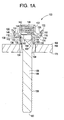
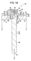
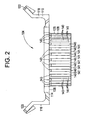
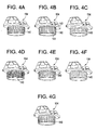
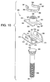
- FIGURES 1-6 A first embodiment depicting steps of the method of securing a nut plate 100 is shown in FIGURES 1-6 , an alternative nut plate 200 therefor is shown in FIGURES 7-9 , and a second embodiment of the invention being a nut plate 300 is shown in FIGURES 10-16 .
- Like elements are denoted with like reference numerals with the nut plate used in the first embodiment being in the one hundreds, the alternative nut plate being in the two hundreds, and the second embodiment being in the three hundreds.
- the wall thickness of the tubular portion 108 at the second end 134 of the tubular portion 108 is preferably 0.014 inches and, thus, is larger than the wall thickness of the tubular portion 108 between the outer wall 136 and the shoulder 132 of the tubular portion 108.
- the third inner diameter of the aperture 128 at the second end 134 of the tubular portion 108 is smaller than the second inner diameter of the aperture 128 at the shoulder 132 of the tubular portion 108.
- the lobes 140 also have an angled portion 143 proximate to the undersurface 138 of the bracket portion 110 such that the lobes 140 are thicker proximate to the undersurface 138 of the bracket portion 110.
- the angled portions 143 of the lobes 140 provide for improved torque of the bracket portion 110.
- the nut 102 includes a cylindrical portion 142 and a flat base portion 144 which extends outwardly from the cylindrical portion 142 at one end thereof.
- the cylindrical portion 142 has an aperture 146 therethrough which defines an inner diameter of the cylindrical portion 142.
- the cylindrical portion 142 at the inner diameter is generally threaded such that a workpiece, such as a bolt, can be attached thereto.
- the flat base portion 144 further defines tabs or wings 148, 150 that extend radially outwardly in opposite directions.
- the tabs 148, 150 fit within the slots 124, 126 of the bracket portion 110 of the holding bracket 104, such that the nut 102 is retained against the holding bracket 104 to prevent substantial movement between the nut 102 and the holding bracket 104.
- the tabs 148, 150 are smaller in size than the slots 124, 126 in order to allow the nut 102 limited floating movement relative to the holding bracket 104.
- the nut 102 is then connected to the holding bracket 104 by deflecting outwardly the flanges 120, 122 and the side walls 116, 118 of the holding bracket 104 and inserting the tabs 148, 150 of the nut 102 into the slots 124, 126 of the side walls 116, 118.
- the flanges 120, 122 and the side walls 116, 118 are then allowed to return to their normal position, thus connecting the nut 102 to the holding bracket 104, allowing for floating movement of the nut 102 relative to the holding bracket 104, as illustrated in FIGURE 1a .
- the enlarged head portion 152 Upon application of force F2 to the stem 106, the enlarged head portion 152 meets resistance from the shoulder 132 of the inner wall 130 such that the inner wall 130 is forced to expand radially outwardly as the enlarged head portion 152 deforms to the size of the expanded inner wall 130, with assistance from the cavity 162 in the enlarged head portion 152, if provided.
- the outer wall 136 of the tubular portion 108 continuously expands radially outwardly within the aperture 164 against the wall of the workpiece 166, thus embedding the lobes 140 in the wall of the workpiece in a fixed and intimate engagement with the wall of the aperture 164.
- the angled portions 143 of the lobes 140 embed further into the wall of the workpiece 166 to provide improved torque-out of the holding bracket 104.
- the alternative nut plate 200 includes a nut 202, a bracket 203, a sleeve 205, and a stem 206.
- the nut 202 and the stem 206 of the nut plate 200 are identical in structure to the nut 102 and stem 106 of the nut plate 100 of the first embodiment, these components will not be described again herein with the understanding that the description of the nut 202 is identical to the nut 102 and the description of the stem 206 is identical to the stem 106.
- Like reference numerals will denote like elements.
- bracket 203 and the sleeve 205 are separate components in this embodiment, whereas they are unitary in the previous embodiment as the holding bracket 104.
- bracket 203 and the sleeve 205 combine to form a holding bracket 204.
- the bracket 203 of the nut plate 200 is generally U-shaped in side elevation and includes a base portion 214 and opposed upstanding side walls 216, 218.
- Flanges 220, 222 extend from upper ends of the side walls 216, 218 and project outwardly therefrom. Slots 224, 226 extend through the side walls 216, 218 of the bracket 203.
- the side walls 216, 218 and the flanges 220, 222 are preferably formed of a resilient material.
- a relatively large circular opening 227 is formed at a center of the base portion 214.
- the sleeve 205 includes a tubular portion 208 and a head 209 that extends perpendicular to the tubular portion 208 at a first end 211 of the sleeve 205.
- the head 209 defines tabs or wings 272, 274 that extend radially outwardly in opposite directions.
- the tabs 272, 274 fit within the slots 216, 218 of the bracket 203.
- the tubular portion 208 has an aperture 228 therethrough which defines an inner wall 230 of the tubular portion 208. At the first end 211 of the sleeve 205, the inner wall 230 defines a first inner diameter.
- the inner wall 230 tapers inwardly to provide a shoulder 232 and to define a second inner diameter, with the second inner diameter being smaller than the first inner diameter.
- the inner wall 230 is slightly tapered or stepped such that the inner wall 230 at the second end 213 of the sleeve 205 defines a third inner diameter, with the third inner diameter being smaller than the second inner diameter, and such that the wall thickness of the tubular portion 208 is greater at the second end 213 of the sleeve 205 than proximate to where the shoulder 232 is provided.
- An outer wall 236 of the tubular portion 208 extends from an undersurface 276 of the head 209 to the second end 213 of the sleeve 205.
- Lobes 240 extend outwardly from the outer wall 236 of the sleeve 205.
- the lobes 240 can be formed in many different configurations on the outer wall 236.
- the bracket 203 is placed on a top surface 268 of a workpiece 266 having an aperture 264 such that the opening 227 of the bracket 203 is positioned in alignment with the aperture 264 of the workpiece 266.
- the tubular portion 208 of the sleeve 205 is then inserted through the opening 227 of the bracket 203 and into the aperture 264 of the workpiece 266.
- the aperture 264 has a diameter which is slightly larger than a diameter of the tubular portion 208 of the sleeve 205.
- the side walls 216, 218 of the bracket 203 are deflected to allow the tabs 272, 274 of the head 209 to be inserted into the slots 224, 226 of the side walls 216, 218.
- the enlarged head portion 252 Upon application of force F2 to the stem 206, the enlarged head portion 252 meets resistance from the shoulder 232 of the inner wall 230 such that the inner wall 230 is forced to expand radially outwardly as the enlarged head portion 252 deforms to the size of the expanded inner wall 230 with assistance from the cavity (not shown) in the enlarged head portion 252, if provided.
- the outer wall 236 of the tubular portion 208 expands radially outwardly in the aperture 264 against the wall of the workpiece 266, thus embedding the lobes 240 in the wall of the workpiece 266 in a fixed and intimate engagement with the wall of the aperture 264.
- the sleeve 205, and thus the bracket 203 and the nut 202 are attached to the workpiece 266 and the stem 206 can be discarded.
- a workpiece, such as a bolt, can then be attached to the nut plate 200.
- the enlarged head portion 252 of stem 206 will initially expand the tubular portion 208 as well as place a compressive load on the components to seat them against the upper surface 268 of the workpiece 266.
- the tubular portion 208 will expand to engage the wall of the aperture 264 in the workpiece 266.
- radial forces are established which are sufficient to deform the head portion 252 radially.
- the head portion 252 can handle tolerance variations in the workpiece aperture 264, and will continuously deform the tubular portion 208 radially outward to engage the aperture wall with sufficient force to cause the lobes 240, or alternate structure, on the outer wall 236 of tubular portion 208 to embed in the wall of the aperture 264.
- the increasing wall thickness of the tubular portion 208 insures that radial deformation continues along the entire length of tubular portion 208 to attain the desired degree of engagement of the lobes 240 in the wall of the aperture 264.
- the nut plate 300 of the second embodiment of the invention includes a nut 302, a holding bracket 304, a stem 306 and a retainer 307.
- the stem 306 is identical in structure to the stem 106 of the nut plate 100 of the first embodiment, this component will not be described again herein with the understanding that the description of the stem 306 is identical to the stem 106.
- Like reference numerals will denote like elements.
- the holding bracket 304 is generally Y-shaped in side elevation and includes a tubular portion 308 and a bracket portion 310 which extends outwardly from the tubular portion 308 at a first end 312 thereof.
- the bracket portion 310 includes a base portion 314 and opposed upstanding side walls 316, 318.
- the base portion 314 has a pair of protrusions 317, 319 which protrude upwardly from the base portion 314.
- Protrusion 317 is provided proximate to edge 321 of the base portion 314 and protrusion 319 is provided proximate to edge 323 of the base portion 314.
- Slots 324, 326 extend through the side walls 316, 318 of the bracket portion 310.
- the inner wall 330 is tapered or stepped such that the inner wall 330 at the second end 334 of the tubular portion 308 defines a third inner diameter and thus a wall thickness of the tubular portion 308 at the second end 334 of the tubular portion 308.
- the wall thickness of the tubular portion 308 at the second end 334 of the tubular portion 308 is preferably 0.014 inches and, thus, is larger than the wall thickness of the tubular portion 308 between the outer wall 336 and the shoulder 332 of the tubular portion 308.
- the third inner diameter of the aperture 328 at the second end 334 of the tubular portion 308 is smaller than the second inner diameter of the aperture 328 at the shoulder 332 of the tubular portion 308.
- the outer wall 336 of the tubular portion 308 extends from an undersurface 338 of the bracket portion 310 to the second end 334 of the tubular portion 308.
- Lobes or ribs 340 extend outwardly from the outer wall 336 of the tubular portion 308.
- the lobes 340 can be formed in many different configurations on the outer wall 336, but, preferably, the lobes 340 are formed as best illustrated in FIGURE 13 . As illustrated in FIGURE 13 , the lobes 340 are axially straight along the outer wall 336 such that they extend from the second end 334 of the tubular portion 308 to the undersurface 338 of the bracket portion 310.
- the retainer 307 may be a spring formed from rectangular wire bent into the form illustrated.
- Retainer 307 is preferably one piece and extends from end portion 361 to side portion 363, then to middle portion 365, then to side portion 367, and then to end portion 369. The operation and purpose of the retainer 307 will be discussed further herein.
- the second end 360 of the stem 306 is inserted into the aperture 328 of the tubular portion 308 of the holding bracket 304 at the first end 312 thereof until the enlarged head portion 352 of the stem 306 meets resistance from the shoulder 332 of the inner wall 330 of the tubular portion 308, as illustrated in FIG. 12a .
- the tubular portion 308 of the holding bracket 304 is then inserted into an aperture 364 of a workpiece 366, such that the undersurface 338 of the bracket portion 310 of the holding bracket 304 sits on a top surface 368 of the workpiece 366, as illustrated in FIGURE 12b .
- the aperture 364 has a diameter which is slightly larger than a diameter of the tubular portion 308 of the holding bracket 304, which includes the lobes 340.
- the aperture 364 has a length which is preferably larger than or equal to a length of the tubular portion 308 of the holding bracket 304 such that the tubular portion 308 does not extend beyond the aperture 364 of the workpiece 366.
- the enlarged head stem 352 will consistently have an outer diameter which is larger than the diameter of the inner wall 330 of the tubular portion 308, even though the enlarged stem head 352 deforms to assume the geometry relevant to the size of the expanded inner wall 330 of the tubular portion 308.
- the axial force F2 applied to the enlarged stem head 352 will place a continuous exertion of radial expansion on the inner wall 330 of the tubular portion 308.
- the enlarged head portion 352 of the stem 306 will initially expand the tubular portion 308 as well as place a compressive load on the components to seat them against the upper surface 368 of the workpiece 366.
- the tubular portion 308 will expand to engage the wall of the aperture 364 in the workpiece 366.
- radial forces are established which are sufficient to deform the head portion 352 radially.
- the head portion 352 can handle tolerance variations in the workpiece aperture 364, and will continuously deform the tubular portion 308 radially outward to engage the aperture wall with sufficient force to cause the lobes 340, or alternate structure, on the outer wall 336 of tubular portion 308 to embed in the wall of the aperture 364.
- the increasing wall thickness of the tubular portion 308 insures that radial deformation continues along the entire length of tubular portion 308 to attain the desired degree of engagement of the lobes 340 in the wall of the aperture 364 such that improved torque-out, push-out and fatigue characteristics are achieved.
- the alternative embodiment of the holding bracket 304a illustrated in FIGURE 16 provides improved push-out characteristics over the holding bracket 304 as the holding bracket 304a includes the lip 335a provided at the second end 334a of the tubular portion 308a. As the lip 335a is provided, the stem 306 will push and embed even more material into the wall of the aperture 364 such that improved push-out characteristics are achieved.
- the nut plates 100, 200, 300 of the embodiments of the present invention provide for a number of benefits over the nut plates of the prior art. Namely, the nut plates 100, 200, 300 have improved torque-out, push-out and fatigue characteristics in comparison to nut plates of the prior art; the nut plates 100, 200, 300 are lighter in weight than nut plates of the prior art, thus reducing operating cost; the nut plates 100, 200, 300 have an increased grip range, thus reducing fastener inventory; the nut plates 100, 200, 300 do not require counter-bore/counter-sink in the workpieces, thus providing for lower installation cost; the nut plates 100, 200, 300 do not require flaring, thus providing for lower installation cost; the nut plates 100, 200, 300 do not require any special aperture preparation, thus providing for lower installation cost; the nut plates 100, 200, 300 do not cause a gap to be formed between the tubular portions 108, 208, 308 and the wall of the workpiece 166, 266, 366; and the nut plates 100, 200
Landscapes
- Engineering & Computer Science (AREA)
- General Engineering & Computer Science (AREA)
- Mechanical Engineering (AREA)
- Dowels (AREA)
- Insertion Pins And Rivets (AREA)
- Connection Of Plates (AREA)
- Braking Arrangements (AREA)
- Clamps And Clips (AREA)
- Jigs For Machine Tools (AREA)
Applications Claiming Priority (5)
| Application Number | Priority Date | Filing Date | Title |
|---|---|---|---|
| US272721 | 1994-07-08 | ||
| US34510501P | 2001-11-09 | 2001-11-09 | |
| US345105P | 2001-11-09 | ||
| US10/272,721 US7059816B2 (en) | 2001-11-09 | 2002-10-17 | Nut plate |
| PCT/US2002/035508 WO2003042551A2 (en) | 2001-11-09 | 2002-11-05 | Nut plate |
Publications (3)
| Publication Number | Publication Date |
|---|---|
| EP1468196A2 EP1468196A2 (en) | 2004-10-20 |
| EP1468196A4 EP1468196A4 (en) | 2005-09-14 |
| EP1468196B1 true EP1468196B1 (en) | 2008-10-01 |
Family
ID=26955697
Family Applications (1)
| Application Number | Title | Priority Date | Filing Date |
|---|---|---|---|
| EP02778740A Expired - Lifetime EP1468196B1 (en) | 2001-11-09 | 2002-11-05 | Nut plate |
Country Status (11)
| Country | Link |
|---|---|
| US (2) | US7059816B2 (https=) |
| EP (1) | EP1468196B1 (https=) |
| JP (1) | JP4137792B2 (https=) |
| KR (1) | KR100864348B1 (https=) |
| CN (1) | CN100591928C (https=) |
| AU (1) | AU2002340382A1 (https=) |
| BR (1) | BR0213982B1 (https=) |
| CA (1) | CA2463744C (https=) |
| ES (1) | ES2315412T3 (https=) |
| TW (1) | TW580539B (https=) |
| WO (1) | WO2003042551A2 (https=) |
Cited By (1)
| Publication number | Priority date | Publication date | Assignee | Title |
|---|---|---|---|---|
| DE102016105794A1 (de) | 2016-03-30 | 2017-10-05 | Böllhoff Verbindungstechnik GmbH | Befestigungselement |
Families Citing this family (69)
| Publication number | Priority date | Publication date | Assignee | Title |
|---|---|---|---|---|
| US7375277B1 (en) * | 2000-06-26 | 2008-05-20 | Fatigue Technology, Inc. | Double flanged bushings and installation methods |
| US7114900B2 (en) * | 2001-11-09 | 2006-10-03 | Textron Inc. | Push-type rivetless nut plate and method and apparatus for installing same |
| US7059816B2 (en) * | 2001-11-09 | 2006-06-13 | Textron Inc. | Nut plate |
| US20040175252A1 (en) * | 2003-03-03 | 2004-09-09 | Kurczynski Richard J. | Fastener and washer assembly and method of forming same |
| US7448652B2 (en) * | 2003-07-31 | 2008-11-11 | Fatigue Technology Inc. | Tubular metal fitting expandable in a wall opening and method of installation |
| DE10352126A1 (de) * | 2003-11-04 | 2005-08-04 | Metallwarenfabrik Hermann Winker Gmbh & Co. Kg | Befestigungselement |
| US20070053761A1 (en) * | 2004-08-03 | 2007-03-08 | Scott Cohen | Sealed rivetless nut plate |
| US20060075617A1 (en) * | 2004-10-07 | 2006-04-13 | Toosky Rahmatollah F | Performance enhancing repair tool |
| US20060090318A1 (en) * | 2004-11-04 | 2006-05-04 | Toosky Rahmatollah F | Self-aligning tool for installation of pull type fastener |
| US20060150699A1 (en) * | 2005-01-12 | 2006-07-13 | Depuy Spine, Inc. | Instrument for bending spinal rods used in a spinal fixation system |
| WO2006132936A1 (en) * | 2005-06-03 | 2006-12-14 | Fatigue Technology, Inc. | Nut plates and threaded inserts and methods of assembling and installng the same |
| DE102005032699B4 (de) * | 2005-07-14 | 2007-08-23 | Itw Automotive Products Gmbh & Co. Kg | Befestigungsvorrichtung |
| US7591622B2 (en) * | 2005-07-22 | 2009-09-22 | The Boeing Company | Nutmount apparatus |
| DE102005036110A1 (de) * | 2005-08-01 | 2007-02-08 | Sepitec Foundation | Befestigungselement zum Einsetzen in eine Bohrung |
| US7509829B2 (en) | 2005-12-28 | 2009-03-31 | Fatigue Technology, Inc. | Mandrel assembly and method of using the same |
| WO2007082077A1 (en) | 2006-01-11 | 2007-07-19 | Fatigue Technology, Inc. | Bushing kits, bearings, and methods of installation |
| US7823262B2 (en) * | 2006-03-14 | 2010-11-02 | Sps Technologies, Llc | Method of replacing a nut plate fastener assembly |
| FR2899291B1 (fr) * | 2006-03-31 | 2010-11-12 | Airbus France | Ecrou pour la fixation d'un pare-brise d'aeronef et dispositif de fixation d'un pare-brise d'aeronef incorporant ledit ecrou |
| US7698794B2 (en) * | 2006-04-19 | 2010-04-20 | Sps Technologies, Llc | Load control mechanism for pull type tools |
| EP2021635A2 (en) * | 2006-04-27 | 2009-02-11 | Fatigue Technology, Inc. | Wave relieving geometric features in structural members that are radially expandable into workpieces |
| ATE536957T1 (de) * | 2006-04-27 | 2011-12-15 | Fatigue Technology Inc | Ausrichtungsvorrichtung und anwendungsverfahren |
| US7958766B2 (en) * | 2006-06-29 | 2011-06-14 | Fatigue Technology, Inc. | Self-aligning tools and a mandrel with retention sleeve |
| DE202006012668U1 (de) * | 2006-08-18 | 2006-10-12 | Fairchild Fasteners Europe - Camloc Gmbh | Befestigungsanordnung und Einweghülse hierfür |
| KR101468399B1 (ko) | 2006-08-28 | 2014-12-03 | 퍼티구 테크놀로지 인코포레이티드 | 설치/처리 시스템 및 이를 사용하는 방법 |
| US7575404B2 (en) * | 2006-11-01 | 2009-08-18 | Sps Technologies, Llc | Nut plate fastener assembly for composite materials |
| EP2210001B1 (en) * | 2007-10-16 | 2017-08-02 | Fatigue Technology, Inc. | Expandable fastener assembly with deformed collar |
| EP2259884B1 (en) | 2008-03-07 | 2018-11-28 | Fatigue Technology, Inc. | Expandable member with wave inhibitor and methods of using the same |
| US8740152B1 (en) * | 2008-05-01 | 2014-06-03 | Textron Innovations, Inc. | Rivetless nutplates for aircraft |
| WO2010009442A2 (en) * | 2008-07-18 | 2010-01-21 | Fatigue Technology, Inc. | Nut plate assembly and methods of using the same |
| CN101660563B (zh) * | 2008-08-28 | 2011-01-05 | 鸿富锦精密工业(深圳)有限公司 | 连接装置 |
| US8511953B2 (en) * | 2008-12-31 | 2013-08-20 | Rolls-Royce Corporation | Nut plate integral epoxy filled sleeve |
| EP2417369B1 (en) | 2009-04-10 | 2014-04-02 | Fatigue Technology, Inc. | Installable assembly having an expandable outer member and a fastener with a mandrel |
| CN101592177A (zh) * | 2009-07-14 | 2009-12-02 | 贵州航天精工制造有限公司 | 一种带有自锁螺母托板的固定方法及无铆托板自锁螺母 |
| US8647035B2 (en) | 2009-12-16 | 2014-02-11 | Fatigue Technology, Inc. | Modular nut plate assemblies and methods of using the same |
| GB2482162B (en) * | 2010-07-22 | 2012-08-01 | Avdel Uk Ltd | Externally splined fastener |
| CN102091913A (zh) * | 2010-12-19 | 2011-06-15 | 镇江中虎弹簧有限公司 | 一种撞针螺母板的螺纹加工工艺 |
| US8402838B1 (en) | 2011-01-04 | 2013-03-26 | Lockheed Martin Corporation | Nutplate tester |
| WO2012167136A2 (en) | 2011-06-03 | 2012-12-06 | Fatigue Technology, Inc. | Expandable crack inhibitors and methods of using the same |
| WO2012174215A2 (en) | 2011-06-15 | 2012-12-20 | Fatigue Technology, Inc | Modular nut plates with closed nut assemblies |
| EP2809482B1 (en) | 2012-01-30 | 2018-11-07 | Fatigue Technology, Inc. | Processing systems and method of operating the same |
| CN106151230B (zh) * | 2012-06-13 | 2018-08-07 | 中国计量大学 | 一种无法拆卸的螺栓型铆钉的加工方法 |
| BR112015000354A2 (pt) | 2012-08-14 | 2017-06-27 | Greene Tweed Tech Inc | placa de porca sem rebite, montagens de placa de porca sem rebite, peças que contêm fechos de placa de porca sem rebite e métodos relacionados |
| CN102913519A (zh) * | 2012-09-27 | 2013-02-06 | 贵州航太精密制造有限公司 | 一种座圈与夹层板的连接装置 |
| US9404521B2 (en) | 2012-12-12 | 2016-08-02 | Polaris Fastening Consulting, Llc | Self integrating structural insert sleeve |
| US9121432B2 (en) | 2012-12-14 | 2015-09-01 | United Technologies Corporation | Nut plate fastener with elongated fastener aperture |
| JP6231744B2 (ja) * | 2012-12-27 | 2017-11-15 | 日東精工株式会社 | 圧入ファスナーおよびその取付け構造 |
| JP6096521B2 (ja) * | 2013-01-31 | 2017-03-15 | 日本ドライブイット株式会社 | フローティングナットおよびフローティングボルト |
| FR3009353B1 (fr) | 2013-08-05 | 2016-01-22 | Lisi Aerospace | Ecrou flottant |
| US9452819B2 (en) * | 2014-03-24 | 2016-09-27 | The Boeing Company | Flight control surface seal |
| US9759246B2 (en) * | 2014-08-25 | 2017-09-12 | Arconic Inc. | Textured sleeves for fasteners |
| US9599132B2 (en) | 2015-03-09 | 2017-03-21 | Rohr, Inc. | Anti-rotation lug for mounting components together |
| CN104895900A (zh) * | 2015-05-21 | 2015-09-09 | 长春黄金研究院 | 自锁式嵌装螺母 |
| CN105041787A (zh) * | 2015-05-29 | 2015-11-11 | 张家港华日法兰有限公司 | 一种锻造连接件 |
| US10220435B2 (en) | 2015-08-26 | 2019-03-05 | Polaris Fastener Testing And Tooling, Llc | Installation tooling system for buckle and swage type fastener |
| US11458071B2 (en) * | 2017-05-11 | 2022-10-04 | Scalpal Llc | Torque enhancer device for grasping and tooling, and assemblies and uses thereof |
| US11969864B2 (en) | 2017-05-11 | 2024-04-30 | Scalpal Llc | Multi-tier torque enhancer driver and/or receiver and method of using same |
| US10690171B2 (en) | 2017-05-22 | 2020-06-23 | The Boeing Company | Nut element installation tool and method for installing a nut plate assembly |
| EP3685055A4 (en) | 2017-09-22 | 2021-11-10 | Partworks, LLC | RIVETLESS FASTENING TOOL AND INSTALLATION TOOL |
| CN108317136B (zh) * | 2018-01-29 | 2019-12-27 | 北京汽车研究总院有限公司 | 一种螺母板组件及车辆 |
| US10899083B1 (en) * | 2018-03-29 | 2021-01-26 | Kineticure, Llc | Bonded nutplate rapid cure system |
| US10975587B2 (en) | 2019-04-22 | 2021-04-13 | Hydra Pools, Inc. | System for forming swimming pool radius supports |
| CN114109999B (zh) * | 2020-08-31 | 2026-03-17 | 伊利诺斯工具制品有限公司 | 螺母紧固件组件 |
| CN114562507B (zh) * | 2022-03-07 | 2023-12-19 | 浙江吉利控股集团有限公司 | 一种卡扣螺母 |
| US12304153B1 (en) | 2022-08-30 | 2025-05-20 | Kineticure, Llc | Bonded nutplate rapid cure system with fixtured heater |
| US12365146B1 (en) | 2022-08-30 | 2025-07-22 | Kineticure, Llc | Bonded nutplate rapid cure system with fixtured heater |
| CN115467888B (zh) * | 2022-10-11 | 2025-09-26 | 东实(武汉)汽车零部件有限公司 | 一种浮动螺母结构及其安装使用方法 |
| WO2024164250A1 (zh) * | 2023-02-09 | 2024-08-15 | 深圳海润新能源科技有限公司 | 端盖组件、储能装置及用电设备 |
| CN116014317B (zh) * | 2023-02-09 | 2023-06-27 | 深圳海润新能源科技有限公司 | 端盖组件、储能装置及用电设备 |
| US12263520B1 (en) | 2023-06-28 | 2025-04-01 | United States Of America As Represented By The Secretary Of The Air Force | Method for securing a rivet to a plate |
Family Cites Families (104)
| Publication number | Priority date | Publication date | Assignee | Title |
|---|---|---|---|---|
| US2413659A (en) | 1946-12-31 | Combination reversing means | ||
| US3126039A (en) | 1964-03-24 | Nut combination | ||
| US177665A (en) * | 1876-05-23 | Improvement in nut-locks | ||
| US1107544A (en) * | 1913-08-14 | 1914-08-18 | John Edward Ogden | Wall-socket. |
| US1138345A (en) * | 1914-11-25 | 1915-05-04 | Lothar R Zifferer | Expansion-bolt. |
| US1413998A (en) * | 1920-11-03 | 1922-04-25 | Walter B Templeton | Expansion stud |
| US1966835A (en) * | 1932-01-28 | 1934-07-17 | Dardelet Threadlock Corp | Fastening means |
| US2150361A (en) * | 1935-05-20 | 1939-03-14 | Chobert Jacques Franco Gabriel | Method of and apparatus for securing hollow bodies in holes in other bodies |
| US2078411A (en) | 1935-07-05 | 1937-04-27 | F L Mclaughlin Company | Clinch-on nut |
| GB495976A (en) | 1936-06-11 | 1938-11-23 | Elastic Stop Nut Corp | Improvements in or relating to fastening devices |
| US2146461A (en) * | 1937-01-06 | 1939-02-07 | Aviat Developments Ltd | Method of riveting |
| GB532899A (en) * | 1939-08-18 | 1941-02-03 | Stanley Thomas Johnson | Improvements in or relating to tubular rivets |
| US2249923A (en) | 1939-09-21 | 1941-07-22 | Guest Keen & Nettlefolds Ltd | Screw and nut fastening |
| US2333386A (en) | 1941-03-27 | 1943-11-02 | Boots Aircraft Nut Corp | Nut retainer |
| US2304107A (en) | 1941-11-24 | 1942-12-08 | James R Leisure | Nut anchor |
| US2366956A (en) * | 1943-01-13 | 1945-01-09 | Gray Mfg Co | Sound recording and reproducing machine |
| US2421201A (en) | 1943-04-20 | 1947-05-27 | Elastic Stop Nut Corp | Fastening means |
| US2477429A (en) | 1943-05-15 | 1949-07-26 | K A Swanstrom | Holder for fastener elements |
| GB567814A (en) | 1943-07-31 | 1945-03-05 | Guest Keen & Nettlefolds Ltd | Improvements relating to screw and nut fastenings |
| US2438044A (en) | 1944-03-20 | 1948-03-16 | Camloc Fastener Corp | Fastener construction |
| US2560961A (en) | 1947-11-29 | 1951-07-17 | Illinois Tool Works | Fastener |
| CH277209A (de) | 1949-10-06 | 1951-08-31 | Niedergesaess & Co | Spreizdübel. |
| US2649883A (en) | 1950-04-15 | 1953-08-25 | George Leonard Steck | Nut and deformable holder |
| US2802503A (en) | 1953-11-27 | 1957-08-13 | Bell Telephone Labor Inc | Screw mounting having insulating and locking properties |
| US2825380A (en) | 1955-02-14 | 1958-03-04 | Reiner Kenneth | Anchor cage and nut |
| DE1050936B (https=) | 1957-08-20 | 1959-02-19 | ||
| US2976080A (en) | 1958-01-29 | 1961-03-21 | Ford Motor Co | Motor vehicle body mounts |
| US3025897A (en) | 1959-01-12 | 1962-03-20 | Maurice J Gieleghem | Snap-in type caged nuts |
| US2986188A (en) | 1959-01-12 | 1961-05-30 | Gen Dynamics Corp | Self-aligning and sealing clinch nut |
| US3305987A (en) | 1961-09-21 | 1967-02-28 | Floyd E Weaver | Joist-supporting structure and method |
| US3180387A (en) | 1962-10-22 | 1965-04-27 | Dzus Fastener Co | Floating fastener receptacle |
| US3177916A (en) | 1963-02-20 | 1965-04-13 | Rosan Eng Corp | Self-aligning two-part threaded fastener unit |
| GB1010406A (en) | 1963-09-24 | 1965-11-17 | C H Larsson | Furniture fitting |
| US3537499A (en) | 1967-08-16 | 1970-11-03 | Standard Pressed Steel Co | Floating fastener unit |
| US3556570A (en) | 1968-08-15 | 1971-01-19 | Tridair Industries | Fastener |
| US3566662A (en) | 1969-04-28 | 1971-03-02 | Boeing Co | Coldworking method and apparatus |
| US3657957A (en) * | 1969-11-24 | 1972-04-25 | Olympic Screw & Rivet Corp | Rivet |
| BE759772A (fr) | 1969-12-02 | 1971-05-17 | Amerace Esna Corp | Dispositif d'assemblage avec ecrou flottant axial captif |
| US3695324A (en) | 1970-01-09 | 1972-10-03 | Deutsch Fastener Corp | Floating nut assembly |
| US3765078A (en) | 1970-01-09 | 1973-10-16 | Deutsch Fastener Corp | Method of attaching a floating nut to a workpiece |
| NL7109253A (https=) * | 1970-07-08 | 1972-01-11 | ||
| US3698278A (en) * | 1971-03-15 | 1972-10-17 | Vsi Corp | Nut member |
| ES401780A2 (es) | 1971-05-05 | 1975-04-01 | Materiel Et D Equipements Tecn | Perfeccionamientos introducidos en los sistemas constitui- dos por las tuercas prisioneras y sus cajas. |
| US4164807A (en) | 1974-03-19 | 1979-08-21 | King John O Jun | Method of forming a coldworked joint |
| US4015650A (en) | 1975-08-15 | 1977-04-05 | Anderson James C | Caged nut |
| US4187708A (en) | 1977-04-11 | 1980-02-12 | Industrial Wire & Metal Forming, Inc. | Pulling apparatus and method |
| US4186787A (en) | 1977-12-28 | 1980-02-05 | Amerace Corporation | Floating anchor nut assembly and basket member component |
| US4227561A (en) * | 1978-05-05 | 1980-10-14 | Deutsch Fastener Corp. | Sealed fastener |
| US4295766A (en) | 1978-07-27 | 1981-10-20 | Francis Shaw | Self-aligning dome nut |
| US4193435A (en) | 1978-08-31 | 1980-03-18 | Nasa | Floating nut retention system |
| US4405256A (en) | 1981-04-14 | 1983-09-20 | King John O Jun | Cushioned fastener joint |
| US4423619A (en) | 1981-06-15 | 1984-01-03 | Fatigue Technology, Inc. | Apparatus and method for prestressing a countersunk fastener hole |
| US4425780A (en) | 1982-02-10 | 1984-01-17 | Fatigue Technology, Inc. | Apparatus having extended prestressing and sleeve retaining devices for prestressing countersunk fastener holes and method |
| US4471643A (en) | 1982-02-10 | 1984-09-18 | Fatigue Technology, Inc. | Method and apparatus for prestressing fastener holes |
| US4557033A (en) | 1983-07-11 | 1985-12-10 | Fatigue Technology, Inc. | Method of cold expanding and sizing fastener holes |
| US4557650A (en) | 1983-12-20 | 1985-12-10 | Deutsch Fastener Corp. | Fastener retention with improved fatigue life |
| GB8517659D0 (en) * | 1985-07-12 | 1985-08-21 | Avdel Ltd | Self-plugging blind fastener |
| US4884420A (en) | 1986-02-24 | 1989-12-05 | Dennis E. McGoldrick, Trustee | Cage with floating nut assembly |
| US4695212A (en) | 1986-04-25 | 1987-09-22 | Microdot Inc. | Composite channel and plate nut assembly |
| US4768907A (en) | 1986-07-14 | 1988-09-06 | Gauron Richard F | Gang nut assembly |
| FR2606471B1 (fr) | 1986-11-12 | 1989-03-10 | Simmonds Sa | Ecrou encage flottant |
| US4732518A (en) | 1986-12-16 | 1988-03-22 | Deutsch Fastener Corp. | Fatigue-resistant flared fastener |
| US4762451A (en) | 1986-12-29 | 1988-08-09 | General Motors Corporation | Caged nut with isolators |
| US4790701A (en) | 1987-05-08 | 1988-12-13 | Jacobson Mfg. Co., Inc. | Floating fastener retainer assembly with removable fasteners |
| FR2616491B1 (fr) | 1987-06-10 | 1989-09-15 | Simmonds Sa | Ecrou encage flottant perfectionne |
| US4830557A (en) | 1988-01-26 | 1989-05-16 | General Electric Company | Self-aligning floating nut fastener |
| US4828440A (en) | 1988-07-22 | 1989-05-09 | General Motors Corporation | Snap-in nut for frame attachment to body |
| US5096350A (en) | 1988-09-02 | 1992-03-17 | Buell Industries, Inc. | Cage nut |
| DE3831523A1 (de) * | 1988-09-16 | 1990-03-22 | Koenig Verbindungstech Ag | Verfahren zum dichten verschliessen einer bohrung |
| US4934886A (en) | 1988-10-07 | 1990-06-19 | Gulton Industries, Inc. | Fastening assembly and method of fastening |
| US4895484A (en) | 1988-10-25 | 1990-01-23 | Deutsch Fastener Corp. | Fastener with floating nut for use with composite structure |
| US4875816A (en) | 1988-10-31 | 1989-10-24 | Buell Industries, Inc. | Caged fastener |
| US4885829A (en) | 1989-02-16 | 1989-12-12 | Fatigue Technology, Incorporated | Fatigue life enhancement of dovetail connector slots and noncircular openings |
| US4934170A (en) | 1989-02-16 | 1990-06-19 | Fatigue Technology, Incorporated | Fatigue life enhancement of noncircular openings |
| US5083363A (en) | 1990-07-25 | 1992-01-28 | Fatigue Technology, Inc. | Method of installing a grommet in a wall of composite material |
| US5245743A (en) | 1990-07-26 | 1993-09-21 | Fatigue Technology, Inc. | Method of installing a nut mounting grommet |
| US5405228A (en) | 1990-07-26 | 1995-04-11 | Fatigue Technology, Inc. | Nut cage and mount |
| US5096349A (en) | 1990-07-26 | 1992-03-17 | Fatigue Technology, Inc. | Nut mounting grommet |
| US5066180A (en) | 1990-12-07 | 1991-11-19 | Lang Charles F | Easy access nutplate |
| US5103548A (en) | 1991-05-13 | 1992-04-14 | Fatigue Technology, Inc. | Method and apparatus for securing a tubular bushing in a circular opening |
| US5146668A (en) | 1991-06-18 | 1992-09-15 | Bulent Gulistan | Method for manufacturing part for floating nut assembly |
| US5127254A (en) | 1991-07-10 | 1992-07-07 | Fatigue Technology, Inc. | Method and apparatus for split sleeve cold expansion of openings in structural members |
| US5193643A (en) | 1991-07-25 | 1993-03-16 | Saturn Corporation | Nut and retainer assembly |
| DE69311167T2 (de) | 1992-03-10 | 1997-10-02 | Black & Decker Inc | Universaldübel |
| US5305627A (en) | 1992-07-27 | 1994-04-26 | Fatigue Technology, Inc. | Split sleeve cold expansion |
| US5341559A (en) | 1993-04-13 | 1994-08-30 | Fatigue Technology, Inc. | Method and apparatus for securing a tubular bushing in a circular opening |
| US5380136A (en) * | 1993-09-14 | 1995-01-10 | Fatigue Technology, Inc. | Anchor nut mount |
| US5433100A (en) | 1993-11-12 | 1995-07-18 | Fatigue Technology, Inc. | Apparatus for split sleeve and tubular bushing cold expansion |
| DE9409087U1 (de) | 1994-06-03 | 1994-08-04 | SÜKOSIM Sicherheitsmuttern Verbindungselemente GmbH + Co., 74575 Schrozberg | Haltevorrichtung für eine Mutter |
| US5468104A (en) | 1994-08-10 | 1995-11-21 | Fatigue Technology, Inc. | Wall nut assembly |
| FR2740184B1 (fr) | 1995-10-24 | 1998-01-09 | Simmonds Sa | Procede de fixation d'un ecrou encage flottant sur une piece quelconque et assemblage obtenu par ce procede |
| US6183180B1 (en) | 1996-01-19 | 2001-02-06 | Fatigue Technology, Inc. | Wall nut and bolt assemblies |
| US5947518A (en) | 1996-07-11 | 1999-09-07 | Daimlerchrysler Corporation | Bracket with floating tap plate for connecting vehicle suspension to body |
| US5704747A (en) * | 1996-07-16 | 1998-01-06 | Physical Systems, Inc. A Nevada Corp. | Adhesive bonded nutplate assembly with integral liner sleeve |
| US5716178A (en) | 1996-10-08 | 1998-02-10 | Mcdonnell Douglas Corporation | Floating gang channel/nut assembly |
| US5893694A (en) | 1997-10-10 | 1999-04-13 | Eaton Corporation | Caged nut fastener |
| JP3288969B2 (ja) * | 1998-04-07 | 2002-06-04 | 光洋精工株式会社 | 締結構造 |
| US6146071A (en) | 1999-04-14 | 2000-11-14 | Illinois Tool Works, Inc. | Caged nut assembly |
| US6077010A (en) | 1999-06-16 | 2000-06-20 | Fatigue Technology, Inc. | Wall bolt assembly |
| GB0024485D0 (en) * | 2000-10-06 | 2000-11-22 | Wheelsure Ltd | Wheel nut assembly |
| US7059816B2 (en) * | 2001-11-09 | 2006-06-13 | Textron Inc. | Nut plate |
| US7114900B2 (en) * | 2001-11-09 | 2006-10-03 | Textron Inc. | Push-type rivetless nut plate and method and apparatus for installing same |
| US6746192B2 (en) * | 2001-12-27 | 2004-06-08 | Textron Inc. | Anti-rotation tacking rivet having ribs |
| US20060291974A1 (en) * | 2005-06-28 | 2006-12-28 | Mcgee Thomas | Nut insert |
-
2002
- 2002-10-17 US US10/272,721 patent/US7059816B2/en not_active Expired - Lifetime
- 2002-11-05 CA CA002463744A patent/CA2463744C/en not_active Expired - Lifetime
- 2002-11-05 CN CN02822071A patent/CN100591928C/zh not_active Expired - Lifetime
- 2002-11-05 AU AU2002340382A patent/AU2002340382A1/en not_active Abandoned
- 2002-11-05 TW TW091132606A patent/TW580539B/zh not_active IP Right Cessation
- 2002-11-05 BR BRPI0213982-0A patent/BR0213982B1/pt active IP Right Grant
- 2002-11-05 ES ES02778740T patent/ES2315412T3/es not_active Expired - Lifetime
- 2002-11-05 EP EP02778740A patent/EP1468196B1/en not_active Expired - Lifetime
- 2002-11-05 KR KR1020047006911A patent/KR100864348B1/ko not_active Expired - Fee Related
- 2002-11-05 JP JP2003544349A patent/JP4137792B2/ja not_active Expired - Fee Related
- 2002-11-05 WO PCT/US2002/035508 patent/WO2003042551A2/en not_active Ceased
-
2004
- 2004-12-07 US US11/005,829 patent/US7237314B2/en not_active Expired - Lifetime
Cited By (2)
| Publication number | Priority date | Publication date | Assignee | Title |
|---|---|---|---|---|
| DE102016105794A1 (de) | 2016-03-30 | 2017-10-05 | Böllhoff Verbindungstechnik GmbH | Befestigungselement |
| US11073176B2 (en) | 2016-03-30 | 2021-07-27 | Böllhoff Verbindungstechnik GmbH | Fastening element |
Also Published As
| Publication number | Publication date |
|---|---|
| ES2315412T3 (es) | 2009-04-01 |
| US20030091408A1 (en) | 2003-05-15 |
| CN1608176A (zh) | 2005-04-20 |
| KR100864348B1 (ko) | 2008-10-17 |
| JP4137792B2 (ja) | 2008-08-20 |
| JP2005528560A (ja) | 2005-09-22 |
| US7059816B2 (en) | 2006-06-13 |
| WO2003042551A2 (en) | 2003-05-22 |
| WO2003042551A3 (en) | 2004-07-29 |
| AU2002340382A1 (en) | 2003-05-26 |
| EP1468196A4 (en) | 2005-09-14 |
| TW200300823A (en) | 2003-06-16 |
| US20050117994A1 (en) | 2005-06-02 |
| BR0213982A (pt) | 2005-03-01 |
| CN100591928C (zh) | 2010-02-24 |
| US7237314B2 (en) | 2007-07-03 |
| EP1468196A2 (en) | 2004-10-20 |
| TW580539B (en) | 2004-03-21 |
| CA2463744A1 (en) | 2003-05-22 |
| KR20040063141A (ko) | 2004-07-12 |
| BR0213982B1 (pt) | 2011-08-09 |
| CA2463744C (en) | 2009-06-30 |
Similar Documents
| Publication | Publication Date | Title |
|---|---|---|
| EP1468196B1 (en) | Nut plate | |
| US7114900B2 (en) | Push-type rivetless nut plate and method and apparatus for installing same | |
| JP4294644B2 (ja) | クリンチ形ブラインドナット | |
| JP5711593B2 (ja) | ブラインドリベット及びその締結方法 | |
| EP0640771A2 (en) | Blind rivet | |
| JPH07233808A (ja) | 盲リベットとその製造方法 | |
| US4904137A (en) | Rivet installation method and construction | |
| EP1624202A2 (en) | Rivetless nut plate | |
| US4678384A (en) | Controlled expansion blind fastener design | |
| EP0677666B1 (en) | Blind rivet | |
| US4767248A (en) | Fastener for securing panels of composite materials | |
| EP1019206B1 (en) | Sheet joining method and apparatus | |
| CN108349552A (zh) | 齐平安装的保持物件的紧固件 | |
| JP2009103311A (ja) | クリンチ形ブラインドナット | |
| US5567099A (en) | Two-part blind rivet | |
| EP0333202B1 (en) | Blind fastener | |
| EP4336058B1 (en) | An insert element as well as a setting method therefor | |
| KR20050048645A (ko) | 클린치형 블라인드 너트 |
Legal Events
| Date | Code | Title | Description |
|---|---|---|---|
| PUAI | Public reference made under article 153(3) epc to a published international application that has entered the european phase |
Free format text: ORIGINAL CODE: 0009012 |
|
| 17P | Request for examination filed |
Effective date: 20040429 |
|
| AK | Designated contracting states |
Kind code of ref document: A2 Designated state(s): AT BE BG CH CY CZ DE DK EE ES FI FR GB GR IE IT LI LU MC NL PT SE SK TR |
|
| AX | Request for extension of the european patent |
Extension state: AL LT LV MK RO SI |
|
| A4 | Supplementary search report drawn up and despatched |
Effective date: 20050803 |
|
| REG | Reference to a national code |
Ref country code: DE Ref legal event code: 8566 |
|
| RAP1 | Party data changed (applicant data changed or rights of an application transferred) |
Owner name: ACUMENT INTELLECTUAL PROPERTIES, LLC. |
|
| GRAP | Despatch of communication of intention to grant a patent |
Free format text: ORIGINAL CODE: EPIDOSNIGR1 |
|
| RAP1 | Party data changed (applicant data changed or rights of an application transferred) |
Owner name: SPS TECHNOLOGIES, LLC |
|
| GRAS | Grant fee paid |
Free format text: ORIGINAL CODE: EPIDOSNIGR3 |
|
| GRAA | (expected) grant |
Free format text: ORIGINAL CODE: 0009210 |
|
| AK | Designated contracting states |
Kind code of ref document: B1 Designated state(s): ES FR GB IT |
|
| REG | Reference to a national code |
Ref country code: GB Ref legal event code: FG4D |
|
| REG | Reference to a national code |
Ref country code: ES Ref legal event code: FG2A Ref document number: 2315412 Country of ref document: ES Kind code of ref document: T3 |
|
| PLBE | No opposition filed within time limit |
Free format text: ORIGINAL CODE: 0009261 |
|
| STAA | Information on the status of an ep patent application or granted ep patent |
Free format text: STATUS: NO OPPOSITION FILED WITHIN TIME LIMIT |
|
| 26N | No opposition filed |
Effective date: 20090702 |
|
| REG | Reference to a national code |
Ref country code: FR Ref legal event code: PLFP Year of fee payment: 14 |
|
| REG | Reference to a national code |
Ref country code: FR Ref legal event code: PLFP Year of fee payment: 15 |
|
| REG | Reference to a national code |
Ref country code: FR Ref legal event code: PLFP Year of fee payment: 16 |
|
| PGFP | Annual fee paid to national office [announced via postgrant information from national office to epo] |
Ref country code: ES Payment date: 20211201 Year of fee payment: 20 Ref country code: FR Payment date: 20211124 Year of fee payment: 20 Ref country code: GB Payment date: 20211129 Year of fee payment: 20 |
|
| PGFP | Annual fee paid to national office [announced via postgrant information from national office to epo] |
Ref country code: IT Payment date: 20211122 Year of fee payment: 20 |
|
| REG | Reference to a national code |
Ref country code: ES Ref legal event code: FD2A Effective date: 20221125 |
|
| REG | Reference to a national code |
Ref country code: GB Ref legal event code: PE20 Expiry date: 20221104 |
|
| PG25 | Lapsed in a contracting state [announced via postgrant information from national office to epo] |
Ref country code: GB Free format text: LAPSE BECAUSE OF EXPIRATION OF PROTECTION Effective date: 20221104 Ref country code: ES Free format text: LAPSE BECAUSE OF EXPIRATION OF PROTECTION Effective date: 20221106 |