EP1467955B1 - Process for treating an ophthalmic lens - Google Patents
Process for treating an ophthalmic lens Download PDFInfo
- Publication number
- EP1467955B1 EP1467955B1 EP03729246.3A EP03729246A EP1467955B1 EP 1467955 B1 EP1467955 B1 EP 1467955B1 EP 03729246 A EP03729246 A EP 03729246A EP 1467955 B1 EP1467955 B1 EP 1467955B1
- Authority
- EP
- European Patent Office
- Prior art keywords
- layer
- lens
- process according
- inorganic
- organic
- Prior art date
- Legal status (The legal status is an assumption and is not a legal conclusion. Google has not performed a legal analysis and makes no representation as to the accuracy of the status listed.)
- Expired - Lifetime
Links
Images
Classifications
-
- C—CHEMISTRY; METALLURGY
- C03—GLASS; MINERAL OR SLAG WOOL
- C03C—CHEMICAL COMPOSITION OF GLASSES, GLAZES OR VITREOUS ENAMELS; SURFACE TREATMENT OF GLASS; SURFACE TREATMENT OF FIBRES OR FILAMENTS MADE FROM GLASS, MINERALS OR SLAGS; JOINING GLASS TO GLASS OR OTHER MATERIALS
- C03C17/00—Surface treatment of glass, not in the form of fibres or filaments, by coating
- C03C17/34—Surface treatment of glass, not in the form of fibres or filaments, by coating with at least two coatings having different compositions
- C03C17/3411—Surface treatment of glass, not in the form of fibres or filaments, by coating with at least two coatings having different compositions with at least two coatings of inorganic materials
- C03C17/3417—Surface treatment of glass, not in the form of fibres or filaments, by coating with at least two coatings having different compositions with at least two coatings of inorganic materials all coatings being oxide coatings
-
- C—CHEMISTRY; METALLURGY
- C03—GLASS; MINERAL OR SLAG WOOL
- C03C—CHEMICAL COMPOSITION OF GLASSES, GLAZES OR VITREOUS ENAMELS; SURFACE TREATMENT OF GLASS; SURFACE TREATMENT OF FIBRES OR FILAMENTS MADE FROM GLASS, MINERALS OR SLAGS; JOINING GLASS TO GLASS OR OTHER MATERIALS
- C03C17/00—Surface treatment of glass, not in the form of fibres or filaments, by coating
- C03C17/34—Surface treatment of glass, not in the form of fibres or filaments, by coating with at least two coatings having different compositions
- C03C17/42—Surface treatment of glass, not in the form of fibres or filaments, by coating with at least two coatings having different compositions at least one coating of an organic material and at least one non-metal coating
-
- C—CHEMISTRY; METALLURGY
- C03—GLASS; MINERAL OR SLAG WOOL
- C03C—CHEMICAL COMPOSITION OF GLASSES, GLAZES OR VITREOUS ENAMELS; SURFACE TREATMENT OF GLASS; SURFACE TREATMENT OF FIBRES OR FILAMENTS MADE FROM GLASS, MINERALS OR SLAGS; JOINING GLASS TO GLASS OR OTHER MATERIALS
- C03C21/00—Treatment of glass, not in the form of fibres or filaments, by diffusing ions or metals in the surface
-
- C—CHEMISTRY; METALLURGY
- C03—GLASS; MINERAL OR SLAG WOOL
- C03C—CHEMICAL COMPOSITION OF GLASSES, GLAZES OR VITREOUS ENAMELS; SURFACE TREATMENT OF GLASS; SURFACE TREATMENT OF FIBRES OR FILAMENTS MADE FROM GLASS, MINERALS OR SLAGS; JOINING GLASS TO GLASS OR OTHER MATERIALS
- C03C23/00—Other surface treatment of glass not in the form of fibres or filaments
- C03C23/0005—Other surface treatment of glass not in the form of fibres or filaments by irradiation
- C03C23/0055—Other surface treatment of glass not in the form of fibres or filaments by irradiation by ion implantation
-
- G—PHYSICS
- G02—OPTICS
- G02B—OPTICAL ELEMENTS, SYSTEMS OR APPARATUS
- G02B1/00—Optical elements characterised by the material of which they are made; Optical coatings for optical elements
- G02B1/10—Optical coatings produced by application to, or surface treatment of, optical elements
- G02B1/11—Anti-reflection coatings
- G02B1/113—Anti-reflection coatings using inorganic layer materials only
- G02B1/115—Multilayers
-
- G—PHYSICS
- G02—OPTICS
- G02B—OPTICAL ELEMENTS, SYSTEMS OR APPARATUS
- G02B1/00—Optical elements characterised by the material of which they are made; Optical coatings for optical elements
- G02B1/10—Optical coatings produced by application to, or surface treatment of, optical elements
- G02B1/12—Optical coatings produced by application to, or surface treatment of, optical elements by surface treatment, e.g. by irradiation
-
- G—PHYSICS
- G02—OPTICS
- G02B—OPTICAL ELEMENTS, SYSTEMS OR APPARATUS
- G02B1/00—Optical elements characterised by the material of which they are made; Optical coatings for optical elements
- G02B1/10—Optical coatings produced by application to, or surface treatment of, optical elements
- G02B1/14—Protective coatings, e.g. hard coatings
-
- G—PHYSICS
- G02—OPTICS
- G02B—OPTICAL ELEMENTS, SYSTEMS OR APPARATUS
- G02B1/00—Optical elements characterised by the material of which they are made; Optical coatings for optical elements
- G02B1/10—Optical coatings produced by application to, or surface treatment of, optical elements
- G02B1/18—Coatings for keeping optical surfaces clean, e.g. hydrophobic or photo-catalytic films
-
- C—CHEMISTRY; METALLURGY
- C03—GLASS; MINERAL OR SLAG WOOL
- C03C—CHEMICAL COMPOSITION OF GLASSES, GLAZES OR VITREOUS ENAMELS; SURFACE TREATMENT OF GLASS; SURFACE TREATMENT OF FIBRES OR FILAMENTS MADE FROM GLASS, MINERALS OR SLAGS; JOINING GLASS TO GLASS OR OTHER MATERIALS
- C03C2218/00—Methods for coating glass
- C03C2218/30—Aspects of methods for coating glass not covered above
- C03C2218/355—Temporary coating
-
- C—CHEMISTRY; METALLURGY
- C03—GLASS; MINERAL OR SLAG WOOL
- C03C—CHEMICAL COMPOSITION OF GLASSES, GLAZES OR VITREOUS ENAMELS; SURFACE TREATMENT OF GLASS; SURFACE TREATMENT OF FIBRES OR FILAMENTS MADE FROM GLASS, MINERALS OR SLAGS; JOINING GLASS TO GLASS OR OTHER MATERIALS
- C03C2218/00—Methods for coating glass
- C03C2218/30—Aspects of methods for coating glass not covered above
- C03C2218/365—Coating different sides of a glass substrate
-
- Y—GENERAL TAGGING OF NEW TECHNOLOGICAL DEVELOPMENTS; GENERAL TAGGING OF CROSS-SECTIONAL TECHNOLOGIES SPANNING OVER SEVERAL SECTIONS OF THE IPC; TECHNICAL SUBJECTS COVERED BY FORMER USPC CROSS-REFERENCE ART COLLECTIONS [XRACs] AND DIGESTS
- Y10—TECHNICAL SUBJECTS COVERED BY FORMER USPC
- Y10T—TECHNICAL SUBJECTS COVERED BY FORMER US CLASSIFICATION
- Y10T428/00—Stock material or miscellaneous articles
- Y10T428/31504—Composite [nonstructural laminate]
- Y10T428/31507—Of polycarbonate
Definitions
- the present invention relates to a process for obtaining an ophthalmic lens comprising two main sides, the first one at least bearing an external organic or inorganic thin layer modifying the lens surface properties.
- the process allows to obtain an ophthalmic lens comprising two main sides, each one bearing a multilayer coating, the external layer of which is a thin layer with hydrophobic and/or oleophobic properties.
- the ophthalmic lenses bearing a multilayer coating are obtained by deposition on the lens surface of evaporated materials in vacuum enclosures.
- the lenses are located on a rotating carrousel or cover being arranged in the upper part of the vacuum enclosure and wherein locations, more particularly circular holes, are provided, above which lenses are to be located.
- Each round lens is held in contact with the carrousel on the periphery thereof and its side to be coated is oriented toward the treatment area.
- each lens is arranged on an annular ring-shaped independent holding part the diameter of which is slightly lower than the lens diameter so that the lens sits on the ring only on the periphery thereof.
- the ring also comprises elastic means providing a good positioning for the ring.
- the so-formed assembly is then arranged above the chosen carrousel hole, the ring sitting then on the hole periphery and being made integral with the carrousel through appropriate locking means.
- the material to be evaporated is arranged in a crucible being placed on the lower part of the vacuum enclosure and heated generally through an electron beam directed towards the crucible or through a simple Joule effect source according to the nature of the material to be evaporated.
- the evaporated material is then deposited on the side to be treated.
- the evaporation of the first material is ceased and then the evaporation of the second material follows.
- One of the technical problems met upon treatment operations for the second side is that the integrity of the layers deposited on the first side must be preserved, more particularly the integrity of the external layer.
- the external layer of the ophthalmic lens essentially having the goal to modify the surface energy properties, has a very small thickness, generally less than 30 nm, more frequently from 1 to 20 nm, more preferably from 1 to 10 nm.
- the thicknesses may only reach from 2 to 10 nm, or even from 2 to 5 nm.
- the ophthalmic lens may be submitted to a surface treatment such as an ion bombardment (particularly with rare gases, oxygen or mixtures thereof or nitrogen or air), a plasma treatment or, in the case of inorganic lenses, a corona treatment (typically a treatment with an oxygen plasma at a pressure of 10 -2 mbar).
- a surface treatment such as an ion bombardment (particularly with rare gases, oxygen or mixtures thereof or nitrogen or air), a plasma treatment or, in the case of inorganic lenses, a corona treatment (typically a treatment with an oxygen plasma at a pressure of 10 -2 mbar).
- Such an activation treatment may be also carried out so as to prepare the surface of one of the deposited layers before the deposition of the subsequent layer.
- the object being looked for is then essentially to increase the treatment adherence.
- IAD ion-assisted deposition
- the species being generated for the purpose of the activation or compaction treatment are highly energetic and/or reactive and are adapted for altering the already carried out deposits on the lens back side, in particular those lenses located the nearest from the treatment area, i.e. the lenses located on the peripheral part of the carrousel or external crown.
- Such an intermediate part is globally shaped according to the pre-calibrated lens size so as to enclose the lens on the periphery thereof and is forcibly engaged into the holding part.
- the adaptation of the pre-calibrated lens into the above-described holding part is possible.
- the pre-calibrated lens surface does not cover the whole circular hole of the carrousel above which the lens/intermediate part/holding part assembly is arranged and consequently a great part of the circular hole forms an opening for energetic and/or reactive species going-through.
- the opposed lens side to the treatment area becomes more accessible for energetic and/or reactive species and thus likely to be altered.
- WO 01/002496 discloses coated articles comprising a substrate such as glass, coated with a functional coating and a removable protective layer, protecting the substrate and the functional coating from mechanical damage during processing, handling, shipping or storage.
- the protective layer may be a water-soluble polymer, or carbon.
- a blocking layer can be applied over the functional coating prior to applying the protective coating for blocking chemical reactions between the functional coating and the protective layer.
- the blocking layer is not a temporary protective layer, since it is not intended to be eliminated.
- SU 1342886 relates to a method for protecting surfaces of optical glasses from blooming during polishing by applying a temporary protective layer.
- This temporary layer is obtained by drying an aqueous solution of dextrin or polyvinyl pyrrolidone containing borax and a surfactant at room temperature for 15-20 min, followed by depositing a nitro varnish.
- US 5211759 teaches a method for simultaneously coating both sides of ophthalmic lenses using energetic and/or reactive species during plasma polymerization.
- WO 02/092524 discloses a lens, which is not pre-calibrated, comprising a hydrophobic and/or oleophobic coating coated with, a temporary protective layer, said temporary protective layer being a mineral layer comprising a metal fluoride or a mixture of metal fluorides, a metal oxide or a mixture of metal oxides, that imparts to the glass a surface energy at least equal to 15 mJ/m 2 .
- the invention aims at providing a process for reducing or even cancel any problem of alteration for the thin external layer opposed to the treatment area and consists in a process for treating an ophthalmic lens comprising two main sides, at least the first one of which comprising a thin external organic or inorganic layer, said process comprising:
- the invention also relates to a pre-calibrated lens at least one of the sides of which comprises a thin external organic or inorganic layer coated with a temporary protective layer, wherein the temporary protective layer comprises:
- Another object of the invention is a lens comprising a hydrophobic and/or oleophobic coating imparting to the lens a surface energy of 14 mJ/m 2 or less, wherein a multilayer temporary protective layer is deposited onto said coating.
- the invention further relates to a lens comprising two main sides, at least the first one of which comprising a thin external organic or inorganic layer coated with a temporary protective layer, wherein the temporary protective layer comprises a polytetrafluoroethylene-based layer.
- the lens treated according to the invention has already been coated on one of the sides thereof with a thin external layer.
- the thin external inorganic or organic layer is preferably a hydrophobic and/or oleophobic surface coating and in particular a hydrophobic and/or oleophobic surface coating deposited on a mono- or multilayer antireflecting coating.
- the hydrophobic and/or oleophobic coatings are generally applied to lenses comprising an antireflecting coating, in particular with an inorganic material, so as to reduce their soiling tendency , for example with respect to grease deposits.
- the hydrophobic and/or oleophobic coatings are obtained by coating, on the surface of the antireflecting coating, surface energy reducing compounds for the lens.
- Silane-based compounds bearing fluorinated groups particularly one or more perfluorocarbon or perfluoropolyether groups, are most frequently used.
- Examples include silazane, polysilazane or silicone compounds comprising one or more fluorinated groups such as those above-mentioned.
- a known process for obtaining a hydrophobic and/or oleophobic layer consists in applying, on the antireflecting coating, compounds bearing fluorinated groups and Si-R groups, R being a -OH group or a precursor thereof, preferably an alkoxy group. Such compounds may carry out on the antireflecting coating surface, directly or after hydrolysis, polymerization and/or cross-linking reactions.
- the coating of the compounds reducing the lens surface energy is conventionally performed by dipping in a solution of said compound or by vapor phase deposition with this last coating type being preferred.
- the hydrophobic and/or oleophobic coating has a thickness lower than 30 nm, more frequently from 1 to 20 nm, preferably from 1 to 10 nm, more preferably from 2 to 5 nm.
- a checking of the optical properties of the lens may be optionally performed, in particular the antireflecting properties thereof.
- the protective layer is coated directly onto the thin external layer.
- the protective layer should have a sufficient thickness so as to avoid any subsequent alteration of the properties in the thin external layer upon the various lens treating steps.
- the thickness is selected depending on the energy of the reactive species which may incidentally reach the thin external layer surface.
- Such energy may vary from 40 to 150 eV with a current density of 30 to 700 microamperes/cm 2 at the level of the substrate (lens) surface.
- the thickness of the protective layer varies preferably from 5 nm to 10 ⁇ m and the protective layer is preferably continuous.
- the thickness thereof is preferably from 5 to 200 nm, more preferably 10 to 200 nm.
- a thicker protective layer When the process comprises a treatment step with high energy species such as ions from a ion gun or a plasma, a thicker protective layer will be selected.
- the thickness of the protective layer is too weak, there is a risk that the thin hydrophobic and/or oleophobic layer should not be protected sufficiently.
- the thickness of the protective layer is too high, in particular for essentially inorganic protective layers, the inventors have found that mechanical stresses may appear within the layer, which may be prejudicial to the expected properties.
- the protective layer material should be such that it does not alter the surface properties of the hydrophobic and/or oleophobic coating and after the material removal the optical and surface properties of the lens are wholly identical to those shown in the lens before the protective layer deposition.
- the temporary protective layer is of an inorganic material and particularly a metal fluoride or a mixture of metal fluorides, a metal oxide or a mixture of metal oxides.
- fluorides examples include magnesium fluoride MgF 2 , lanthanum fluoride LaF 3 or cerium fluoride CeF 3 .
- Useful oxides are titanium, aluminum, zirconium or praseodymium oxides.
- a particularly recommended commercially available material is the PASO2 from Leybold company.
- temporary protective layers made from an organic material include polytetrafluoroethylene-based layers, for example Teflon®.
- the temporary protective layer itself may have multiple layers, in particular two layers.
- a first layer of an inorganic nature in a small thickness (from 2 to 200 nm, preferably 5 to 200 nm), and then a layer of an organic nature is coated onto such a first layer.
- the layer of an organic nature is obtained by deposition and hardening of a latex.
- the appropriate latexes are acrylic or methacrylic latexes; or polyurethane latexes such as those sold by Baxenden under the trademark W234 and W240.
- the layer of an organic nature coated onto the first inorganic layer is of a thickness much higher than the thickness of the first inorganic layer and the thickness thereof varies typically from 0.2 to 10 ⁇ m.
- the layer of an organic nature affords a good mechanical protection and may be easily removed by tearing away, for example by drawing the layer from the periphery thereof.
- the material of the layer of an organic nature is selected so that the adherence at the interface between the first layer of an inorganic nature and the second layer of an organic layer should be higher than at the interface between the hydrophobic and/or oleophobic layer and the first layer of an inorganic nature.
- the protective layer may be coated through any appropriate conventional process, in a vapor phase (deposition under vacuum) or in a liquid phase, for example spraying, centrifugation or dipping.
- the antireflecting, hydrophobic and/or oleophobic coatings have been deposited by evaporation in vacuum bells and it is preferred to coat the temporary protective layer with the same technique, whereby the set of operations may be performed sequentially without any excessive manipulation of the lenses between the steps.
- Another interest of the vacuum deposition is to prevent any wetability problem in the case where the thin layer on which the protective layer is to be coated shows hydrophobic and/or oleophobic properties.
- the protective layer is preferably made from any material allowing for the lens surface energy having hydrophobic and/or oleophobic properties to be increased and which may be removed upon a subsequent operation following the trimming step.
- the protective layer is made of one or more materials increasing the surface energy with respect to the lens surface having hydrophobic and/or oleophobic properties, such characteristic may be gained profit from for lens trimming.
- an ophthalmic lens results from a sequence of molding, and/or surfacing/polishing operations that define the geometry for both convex and concave optical surfaces of said lens, and then of appropriate surface treatments.
- the last finishing step for the ophthalmic lens is the trimming operation consisting in machining the edge or periphery of the lens so as to shape it to the required size to adapt the lens for the glass frame in which it is supposed to be positioned.
- the trimming is generally performed on a polishing device comprising diamond wheels that perform the machining as defined above.
- the lens is held upon such an operation with axially-acting locking members.
- the relative movement of the lens with respect to the wheel is controlled generally digitally so as to reach the desired shape.
- an acorn-positioning for the lens i.e. a holding means or acorn is placed above the lens convex surface.
- a holding pad such as a self-adhesive chip, for example a double side adhesive, is put between the acorn and the lens convex surface.
- the so-equipped lens is positioned on one of the above-mentioned axial locking members, the second axial locking member being then adapted to lock the lens on the concave side thereof through an abutment, generally an elastomeric one.
- a tangential torque effort is generated on the lens, which may result in a lens rotation with respect to the acorn if the lens-holding system is not efficient.
- the good lens holding mainly depends on the good adherence at the interface between the holding pad and the lens convex surface.
- the invention also relates to a lens, for example an ophthalmic lens, comprising a hydrophobic and/or oleophobic coating on which a multilayer, particularly a bilayer temporary protective layer, as defined above and preferably imparting to the lens a surface energy of at least 15 mJoules/m 2 .
- a hydrophobic and/or oleophobic surface coating a surface energy lower than 14 mJoules/m 2 and very frequently lower than or equal to 12 mJoules/m 2 .
- the multiple temporary protective layer will increase the lens surface energy up to a value of at least 15 mJoules/m 2 .
- the surface energies are calculated according to Owens-Wendt method disclosed in the following reference: " Estimation of the surface force energy of polymers", Owens D.K., Wendt R.G. (1969) J. APPL. POLYM. SCI., 13, 1741-1474 .
- the process of the invention may also be applied to lenses having already been submitted to a trimming step one side of which comprises a thin external organic and inorganic layer, preferably a hydrophobic and/or oleophobic one.
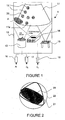
- a vacuum machine 1 for implementing the process according to the invention.
- a vacuum machine 1 comprising a vacuum enclosure 10 within which a carrousel 11 provided with circular openings 12 adapted to receive the lenses to be treated, a bombardment device 13 acting with energetic and/or reactive species, for example an ion gun, a first material evaporating 14 such as for example an electron gun comprising a central crucible to contain the materials to be evaporated and a second material evaporation device 15, for example a Joule effect device.
- a first material evaporating 14 such as for example an electron gun comprising a central crucible to contain the materials to be evaporated
- a second material evaporation device for example a Joule effect device.
- Devices 16, 17, 18 such as mass flowmeters, are also provided for feeding appropriate gases such as argon and oxygen, to the bombardment device and such as oxygen, to the enclosure 10 of the machine, from external sources (not shown).
- gases such as argon and oxygen
- the alteration of the back side of the lenses mainly occurs at the level of the external crown 11a of the carrousel 11 and more particularly in the squared area A.
- Fig. 2 shows schematically a detail of the fastening of a pre-calibrated lens 20.
- a pre-calibrated lens is held with an intermediate part 21, adapted to the pre-calibrated lens shape, in the present case a triangular-like open spring holding the pre-calibrated lens by pinching between its branches.
- Such an intermediate part 21 is itself held by its three apexes in the conventional holding ring 22 used to hold round lenses in the openings 12 of the carrousel 11.
- the process of the invention may be as an example implemented by using the machine according to Fig. 1 as follows.
- the lenses to be treated are placed in the openings 12 of the carrousel 11, for example, with their concave sides exposed to the evaporation devices 14, 15 and the ion gun 13.
- the activation of the lens concave surface by ion bombardment is conventionally performed, and afterwards a conventional deposition under vacuum of a multilayer antireflecting coating through the evaporation device 14, and then a thin external layer of a hydrophobic and/or oleophobic coating, for example, through the Joule effect device.
- a deposition of the external temporary protective layer is then performed for example through the evaporation device 14.
- the lenses are then put upside down and the convex side may be treated in a similar manner with no risk of alteration of the thin external hydrophobic/oleophobic layer of the concave side.
- the temporary protective layers are removed.
- the protective layer is of a material increasing the surface energy of the external layer, it may be kept to favor the acorn-positioning for the lens during the trimming operation.
- the temporary protective layer removing step may be carried out either in a liquid medium or by a dry wiping or even by a successive implementation of both those means or even by tearing away in the case of a bilayer, in particular a bilayer comprising a first layer of an inorganic nature and a second layer of an organic nature as described above.
- the removal step in a liquid medium is preferably carried out with an acidic solution, in particular an orthophosphoric acid solution at molarities varying from 0.01 to 1 N.
- the acidic solution may also comprise anionic, cationic or amphoteric surfactants.
- the temperature at which the removal step is made is variable, but generally the step is performed at room temperature.
- the removal of the temporary protective layer may also be favored with a mechanical action, preferably by using ultrasounds.
- the removal step comprises a cleaning step with an aqueous solution of a pH substantially equal to 7.
- the lens has optical and surface treatment characteristics of the same order, even quasi identical to those of the initial lens comprising the hydrophobic and/or oleophobic coating.
- the lenses comprising a temporary protective layer in an inorganic material may be marked with various inks currently used by the man in the art for progressive lenses.
- the process is disclosed more particularly in the case of a deposition of antireflecting layers by conventional evaporation, the use of a temporary protective layer may be advantageously employed in the case of other deposition processes, such as the sputtering processes wherein the energies of the deposited particles vary from 10 to 40 eV under pressures from 10 -1 to 10 -3 mbar, and the plasma-assisted chemical vapor phase processes, for which the particle energy varies from 1 to 10 eV under pressures from 10 -1 to 10 -3 mbar.
- substrates which are CR39®-based ophthalmic lenses comprising on both sides a polysiloxane-type anti-abrasive coating corresponding to Example 3 of Patent Application EP614957 .
- the lenses are washed in an ultrasonic cleaning vessel and steamed for 3 hours minimum at a temperature of 100°C. They are then ready to be treated.
- the vacuum treatment machine used is a machine Balzers BAK760 provided with an electron gun, an ion gun of the type "end-Hall" Mark2 Commonwealth and a Joule effect evaporation source.
- the lenses are put on the carrousel with the concave side exposed to the evaporation sources and the ion gun.
- the round lenses are arranged on the external crown of the carrousel (in the most treatment sensitive area) and in the central part of the carrousel.
- the pre-calibrated lenses are also arranged both on the external crown and the central part of the carrousel.
- a vacuum drawing is performed until a secondary vacuum is reached.
- the substrate surface is activated by bombardment with argon and oxygen (Ar and O 2 ) ion beam through the ion gun of the model type "end-Hall" Mark2 from Commonwealth.
- the gun is set so that the ion energy should be 80 eV and the current density at the level of the substrate in the gun axis be from 40 to 70 microamperes per cm 2 .
- the substrates are exposed to the ion bombardment during 1 minute.
- a sequential evaporation is carried out with the electron gun to form 4 optical antireflecting layers of high index (HI), low index (LI), HI, LI: ZrO 2 , SiO 2 , ZrO 2 , SiO 2 .
- a layer of a hydrophobic and oleophobic coating is deposited by evaporation of a product of trademark OPTOOL DSX (compound comprising perfluoropropylene patterns) sold by DAIKIN.
- a determined quantity of Optool DSX is put in a copper cup of 18 mm diameter being itself arranged in a Joule effect crucible (tantalum crucible).
- a 2 nm thickness of a hydrophobic and oleophobic coating is then deposited by evaporation.
- the checking of the deposited thickness is carried out with quartz scales.
- the evaporation of the protective layer is then carried out.
- the deposited material is a compound of formula MgF 2 with a particle size from 1 to 2.5 mm sold by Merck.
- the evaporation is performed with the electron gun.
- the physical thickness deposited is 20 nm, at a deposition rate of 0.52 nm/s.
- the checking of the thickness deposited is carried out with quartz scales.
- the enclosure is heated and the treatment chamber is put again at the room atmosphere.
- the lenses are then put upside down with their convex side oriented towards the treatment area.
- the convex side is treated identically with the concave side (by reproducing the steps 1.1 and 1.2 above-mentioned).
- the temporary layer of MgF 2 coated on the convex side in the last step has then the objective to increase the surface energy of the convex side so as to be able to perform an acorn-positioning operation, i.e. for positioning said side through a holding means or acorn, thereby serving to hold the lens during the final machining operation of the lens periphery (trimming) so as to adapt it to the frame shapes.
- the lenses are trimmed through a polishing device and finally mounted on the frame.
- the lenses are wiped with the help of a usual cotton cloth to remove the temporary protective layer.
- the colorimetric values after the removal of the MgF 2 layer are the same as those of the treatment with no MgF 2 : the MgF 2 and the removal operation thereof do no modify the colorimetric characteristics of the antireflecting treatment.
- the substrates are varnished CR39® ophthalmic lenses similar to those used in Example 1. They are washed in an ultrasonic cleaning vessel and then steamed during 3 hours minimum at a temperature of 100°C.
- the vacuum treatment machine used is a machine Leybold LH1104 provided with an electron gun, an ion gun of the type Mark2 and a Joule effect evaporation source.
- the lenses are put on the carrousel with the concave side exposed to the evaporation sources and the ion gun.
- the round lenses are arranged both on the external crown of the carrousel (in the most treatment sensitive area) and in the central part of the carrousel.
- the pre-calibrated lenses are also arranged both on the external crown and the central part of the carrousel.
- a vacuum drawing is performed until a secondary vacuum is reached.
- a sequential evaporation is carried out by heating of the source with the electron gun to form 4 optical antireflecting layers of high index (HI), low index (LI), HI, LI: ZrO 2 , SiO 2 , ZrO 2 , SiO 2 .
- the third layer of ZrO2 is evaporated with the technical assistance (IAD) to improve its compaction.
- the ion gun is operated at the same time as the electron gun.
- An ZrO2 material OPTRON is evaporated in presence of an oxygen ion flow.
- the ion gun is set so that the ion energy should be 120 eV and the current density at the level of the substrate in the axis of the ion gun be from 50 to 70 microamperes per cm 2 .
- a hydrophobic and oleophobic coating is deposited by evaporation by Joule effect of a product of trademark OPTOOL DSX (compound comprising perfluoropropylene patterns) sold by DAIKIN.
- the product under a liquid form is poured into a copper cup of 18 mm diameter being it self arranged in a Joule effect crucible (tantalum crucible).
- a 2 nm thickness of a hydrophobic and oleophobic coating is then deposited by evaporation.
- the checking of the deposited thickness is carried out with quartz scales.
- the temporary layer is deposited according to the same procedure as in step 1.2 above.
- the lenses are then put upside down with their convex side oriented towards the treatment area and treated identically with the concave side, by reproducing the steps 2.1 and 2.2 above-mentioned.
- the lenses are trimmed and then mounted into the frame.
- the procedure is the same as the step 1.3 above.
- Example 1 is identically reproduced, but without the steps of deposition and then removal of the temporary layer of MgF 2 (steps 1.2 and 1.3)
- Example 2 is identically reproduced, but without the steps of deposition and then removal of the temporary layer of MgF 2 (steps 2.2 and 2.3).
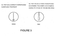
- the operator pours an oil droplet commercially available under the trademark "three in one" with WD40 company onto the concave or convex surface of the lens to be tested with a pipette and tilts the lens so as to allow the droplet to flow on the surface under its own weight.
- the oil does not wet, but retracts.
- the trace is discontinuous.
- the oil wets.
- the trace is continuous and well marked.
- This test is very selective and allows to highlight a very weak increase of the surface energy.
Landscapes
- Chemical & Material Sciences (AREA)
- Physics & Mathematics (AREA)
- Chemical Kinetics & Catalysis (AREA)
- Engineering & Computer Science (AREA)
- General Chemical & Material Sciences (AREA)
- Geochemistry & Mineralogy (AREA)
- Organic Chemistry (AREA)
- Materials Engineering (AREA)
- Life Sciences & Earth Sciences (AREA)
- Optics & Photonics (AREA)
- General Physics & Mathematics (AREA)
- Toxicology (AREA)
- Health & Medical Sciences (AREA)
- Plasma & Fusion (AREA)
- Inorganic Chemistry (AREA)
- Surface Treatment Of Optical Elements (AREA)
- Eyeglasses (AREA)
- Surface Treatment Of Glass (AREA)
- Physical Vapour Deposition (AREA)
- Laminated Bodies (AREA)
Applications Claiming Priority (3)
| Application Number | Priority Date | Filing Date | Title |
|---|---|---|---|
| FR0200388A FR2834712B1 (fr) | 2002-01-14 | 2002-01-14 | Procede de traitement d'un verre ophtalmique |
| FR0200388 | 2002-01-14 | ||
| PCT/EP2003/000226 WO2003057641A1 (en) | 2002-01-14 | 2003-01-13 | Process for treating an ophthalmic lens |
Related Child Applications (1)
| Application Number | Title | Priority Date | Filing Date |
|---|---|---|---|
| EP10012093 Division-Into | 2010-09-30 |
Publications (2)
| Publication Number | Publication Date |
|---|---|
| EP1467955A1 EP1467955A1 (en) | 2004-10-20 |
| EP1467955B1 true EP1467955B1 (en) | 2014-04-09 |
Family
ID=8871277
Family Applications (1)
| Application Number | Title | Priority Date | Filing Date |
|---|---|---|---|
| EP03729246.3A Expired - Lifetime EP1467955B1 (en) | 2002-01-14 | 2003-01-13 | Process for treating an ophthalmic lens |
Country Status (11)
| Country | Link |
|---|---|
| US (1) | US7629053B2 (ko) |
| EP (1) | EP1467955B1 (ko) |
| JP (2) | JP4495463B2 (ko) |
| KR (1) | KR100949350B1 (ko) |
| CN (1) | CN1871180B (ko) |
| AU (1) | AU2003235808B2 (ko) |
| CA (1) | CA2472909C (ko) |
| ES (1) | ES2478621T3 (ko) |
| FR (1) | FR2834712B1 (ko) |
| PT (1) | PT1467955E (ko) |
| WO (1) | WO2003057641A1 (ko) |
Families Citing this family (38)
| Publication number | Priority date | Publication date | Assignee | Title |
|---|---|---|---|---|
| FR2834712B1 (fr) | 2002-01-14 | 2004-12-17 | Essilor Int | Procede de traitement d'un verre ophtalmique |
| FR2856056B1 (fr) * | 2003-06-13 | 2009-07-03 | Essilor Int | Procede de traitement d'un verre apte au debordage. |
| FR2860303A1 (fr) * | 2003-09-26 | 2005-04-01 | Essilor Int | Lentille ophtalmique recouverte d'un film electrostatique et procede de debordage d'une telle lentile. |
| FR2860306B1 (fr) * | 2003-09-26 | 2006-09-01 | Essilor Int | Lentille ophtalmique recouverte d'un film electrostatique et procede de debordage d'une telle lentille |
| DE102004044441B3 (de) * | 2004-09-14 | 2006-06-01 | Rodenstock Gmbh | Verbesserung des Einschleif- und Anstempelverhaltens von Brillengläsern mit hydrophober Beschichtung |
| US7829198B2 (en) * | 2005-03-03 | 2010-11-09 | Nikon-Essilor Co., Ltd | Lens for spectacles and method for forming lens for spectacles |
| US20060210783A1 (en) * | 2005-03-18 | 2006-09-21 | Seder Thomas A | Coated article with anti-reflective coating and method of making same |
| DE102005014031A1 (de) * | 2005-03-23 | 2006-09-28 | Leybold Optics Gmbh | Beschichtetes Substrat mit einer temporären Schutzschicht sowie Verfahren zu seiner Herstellung |
| US20070141358A1 (en) * | 2005-12-19 | 2007-06-21 | Essilor International Compagnie Generale D'optique | Method for improving the edging of an optical article by providing a temporary layer of an organic material |
| EP1999220B1 (en) | 2006-03-27 | 2019-02-13 | Essilor International | Edging process of lens using transparent coating layer for protecting lens |
| FR2901552B1 (fr) * | 2006-05-26 | 2008-07-11 | Essilor Int | Article d'optique comportant un revetement externe hydrophobe et/ou oleophobe revetu d'une couche temporaire |
| FR2913116B1 (fr) * | 2007-02-23 | 2009-08-28 | Essilor Int | Procede de fabrication d'un article optique revetu d'un revetement anti-reflets ou reflechissant ayant des proprietes d'adhesion et de resistance a l'abrasion ameliorees |
| US8318245B2 (en) * | 2007-02-23 | 2012-11-27 | Essilor International (Compagnie Generale D'optique) | Method for producing an optical article coated with an antireflection or a reflective coating having improved adhesion and abrasion resistance properties |
| FR2921161B1 (fr) * | 2007-09-14 | 2010-08-20 | Essilor Int | Procede de preparation de la surface d'une lentille comportant un revetement anti-salissures en vue de son debordage |
| FR2921162B1 (fr) * | 2007-09-14 | 2010-03-12 | Essilor Int | Article d'optique comportant un revetement temporaire bicouche |
| FR2924233A1 (fr) * | 2007-11-23 | 2009-05-29 | Essilor Int | Article d'optique comportant une couche temporaire de polyurethane thermoplastique aliphatique et application au debordage |
| JP4693836B2 (ja) * | 2007-12-17 | 2011-06-01 | 日本電波工業株式会社 | 赤外線カットフィルタ及びその製造方法 |
| EP2333132A4 (en) * | 2008-09-05 | 2013-01-30 | Shincron Co Ltd | FILM-FORMING PROCESS AND OIL-REPELLENT BASIS THEREFOR |
| JP4688230B2 (ja) * | 2008-10-09 | 2011-05-25 | 株式会社シンクロン | 成膜方法 |
| US20100102025A1 (en) * | 2008-10-28 | 2010-04-29 | Essilor International (Compagnie Generale D'optique) | Method and apparatus for marking coated ophthalmic substrates or lens blanks having one or more electrically conductive layers |
| FR2938255B1 (fr) | 2008-11-13 | 2011-04-01 | Essilor Int | Procede de traitement au moyen d'un film adhesif d'une lentille optique comportant un revetement antisalissure en vue de son debordage |
| CN101458222B (zh) * | 2008-12-26 | 2011-12-21 | 江南大学 | 一种花生或河虾过敏原快速检测传感器的制备及应用 |
| US8691331B2 (en) * | 2009-02-09 | 2014-04-08 | Prashant D. Santan | Surface modification of hydrophobic and/or oleophobic coatings |
| FR2957455B1 (fr) * | 2010-03-09 | 2012-04-20 | Essilor Int | Enveloppe de protection pour canon a ions, dispositif de depot de materiaux par evaporation sous vide comprenant une telle enveloppe de protection et procede de depot de materiaux |
| FR2965820B1 (fr) | 2010-10-12 | 2012-11-16 | Essilor Int | Article comprenant une couche mesoporeuse protegee par un revetement faisant barriere au sebum et procede de fabrication |
| BR112013029191B1 (pt) | 2011-05-12 | 2020-12-29 | Essilor International | Artigo óptico compreendendo um revestimento precursor de um revestimento antiembaçante e uma camada temporária tornando-o adequado para rebordagem |
| FR2997943B1 (fr) | 2012-11-09 | 2014-12-26 | Essilor Int | Article d'optique comportant un revetement precurseur d'un revetement antibuee et une couche temporaire a base de fluorures metalliques ou de composes comprenant du magnesium et de l'oxygene |
| CN103105632A (zh) * | 2012-11-09 | 2013-05-15 | 江苏淘镜有限公司 | 真空镀膜方法得到的超防水保护膜 |
| US9726787B2 (en) * | 2012-12-28 | 2017-08-08 | Essilor International (Compagnie Generale D'optique | Method for the production of an optical article with improved anti-fouling properties |
| FR3000568B1 (fr) * | 2012-12-28 | 2015-03-13 | Essilor Int | Lentille ophtalmique apte au debordage comprenant une bicouche hydrophobe et une couche temporaire de fluorure metallique |
| WO2014102271A1 (en) * | 2012-12-28 | 2014-07-03 | Essilor International (Compagnie Generale D'optique) | Method for the production of an optical article with improved anti-fouling properties |
| FR3014210B1 (fr) * | 2013-12-03 | 2016-01-01 | Satisloh Ag | Article d'optique comportant un revetement precurseur d'un revetement antibuee ayant des proprietes antisalissure |
| US10436949B2 (en) | 2014-05-20 | 2019-10-08 | Essilor International | Optical lens coated with a patterned removable film and method for edging such a lens |
| FR3023381B1 (fr) | 2014-07-03 | 2016-08-12 | Essilor Int | Lentille ophtalmique ayant des proprietes antisalissure differenciees sur ses deux faces et procedes de fabrication |
| CN108385060B (zh) * | 2018-03-06 | 2020-08-07 | 深圳市科益实业有限公司 | 眼镜片制作方法及制作装置 |
| EP3800167A1 (en) | 2019-10-04 | 2021-04-07 | Essilor International | Article with a hydrophilic surface coated with a temporary super-hydrophobic film and process for obtaining same |
| WO2021064248A1 (en) | 2019-10-04 | 2021-04-08 | Essilor International | Article with a hydrophobic surface coated with a temporary super-hydrophobic film providing antirain functionality and process for obtaining same |
| CN112117546B (zh) * | 2020-09-17 | 2022-01-21 | 中国人民解放军国防科技大学 | C波段超宽带能量选择表面 |
Family Cites Families (48)
| Publication number | Priority date | Publication date | Assignee | Title |
|---|---|---|---|---|
| US2392768A (en) * | 1942-06-18 | 1946-01-08 | Libbey Owens Ford Glass Co | Temporary protective coatings |
| US2536075A (en) * | 1945-08-08 | 1951-01-02 | Samuel W Macnutt | Method for removing baked magnesium fluoride films from optical glass |
| SE435297B (sv) * | 1975-08-22 | 1984-09-17 | Bosch Gmbh Robert | Optiska reflektorer framstellda genom att reflektorytan belegges med ett skyddsskikt |
| JPS56138701A (en) * | 1980-03-31 | 1981-10-29 | Minolta Camera Co Ltd | Antireflection film |
| US4410563A (en) | 1982-02-22 | 1983-10-18 | The United States Of America As Represented By The Secretary Of The Navy | Repellent coatings for optical surfaces |
| JPS60135167A (ja) | 1983-12-24 | 1985-07-18 | Masato Nishikata | レンズの表面処理方法 |
| DE3688604T2 (de) | 1985-04-30 | 1993-10-28 | Toray Industries | Optisches Gerät und Verfahren zu dessen Herstellung. |
| SU1342886A1 (ru) * | 1986-02-12 | 1987-10-07 | Предприятие П/Я В-2038 | Способ защиты полированной поверхности оптических деталей |
| FR2613275B1 (fr) * | 1987-03-30 | 1989-06-09 | Essilor Int | Procede et appareil pour coller un film protecteur sur une face d'une serie de lentilles ophtalmiques |
| US5328768A (en) * | 1990-04-03 | 1994-07-12 | Ppg Industries, Inc. | Durable water repellant glass surface |
| DE59202577D1 (de) * | 1991-03-05 | 1995-07-27 | Balzers Hochvakuum | Verfahren zur Herstellung einer doppelseitigen Beschichtung von optischen Werkstücken. |
| JPH063503A (ja) * | 1992-06-18 | 1994-01-14 | Seiko Epson Corp | 眼鏡用レンズの反射防止膜蒸着装置 |
| JPH07509411A (ja) * | 1992-07-17 | 1995-10-19 | ミネソタ マイニング アンド マニュファクチャリング カンパニー | レンズ処理法とそれに使用する手段 |
| US5343657A (en) * | 1992-09-18 | 1994-09-06 | Venture Tape Corporation | Method and apparatus for masking removable optical lens markings during lens grinding |
| FR2702486B1 (fr) | 1993-03-08 | 1995-04-21 | Essilor Int | Compositions de revêtement antiabrasion à base d'hydrolysats de silanes et de composés de l'aluminium, et articles revêtus correspondants résistants à l'abrasion et aux chocs. |
| GB9317170D0 (en) * | 1993-08-18 | 1993-10-06 | Applied Vision Ltd | Improvements in physical vapour deposition apparatus |
| US5680013A (en) * | 1994-03-15 | 1997-10-21 | Applied Materials, Inc. | Ceramic protection for heated metal surfaces of plasma processing chamber exposed to chemically aggressive gaseous environment therein and method of protecting such heated metal surfaces |
| FR2722493B1 (fr) * | 1994-07-13 | 1996-09-06 | Saint Gobain Vitrage | Vitrage hydrophobe multicouches |
| US5582907A (en) * | 1994-07-28 | 1996-12-10 | Pall Corporation | Melt-blown fibrous web |
| EP0749021B1 (en) | 1995-06-15 | 2003-03-26 | Sumitomo Chemical Company, Limited | Antireflection filter |
| US6183872B1 (en) | 1995-08-11 | 2001-02-06 | Daikin Industries, Ltd. | Silicon-containing organic fluoropolymers and use of the same |
| JPH0961604A (ja) * | 1995-08-28 | 1997-03-07 | Toyo Metallizing Co Ltd | プラスティック反射防止フィルム |
| AU7360696A (en) * | 1995-09-18 | 1997-04-09 | Minnesota Mining And Manufacturing Company | Thermoplastic lens blocking material |
| US6149750A (en) | 1995-09-18 | 2000-11-21 | 3M Innovative Properties Company | Lens blank surface protection film |
| JPH101553A (ja) * | 1996-06-13 | 1998-01-06 | Toyo Metallizing Co Ltd | 防汚性プラスチックフィルムの製法 |
| JPH1026703A (ja) * | 1996-07-09 | 1998-01-27 | Nikon Corp | 撥水処理されたレンズ |
| US6277485B1 (en) * | 1998-01-27 | 2001-08-21 | 3M Innovative Properties Company | Antisoiling coatings for antireflective surfaces and methods of preparation |
| JP4733798B2 (ja) | 1998-01-31 | 2011-07-27 | 凸版印刷株式会社 | 防汚剤、防汚層の形成方法、光学部材、反射防止光学部材、光学機能性部材及び表示装置 |
| US6143358A (en) * | 1998-10-01 | 2000-11-07 | Nanofilm, Ltd. | Hydrophobic thin films on magnesium fluoride surfaces |
| JP2000147204A (ja) * | 1998-11-06 | 2000-05-26 | Nikon Corp | 保護膜を具える光学素子及びその製造方法及び光学装置及び半導体露光装置 |
| US6413413B1 (en) * | 1998-12-31 | 2002-07-02 | Catalytic Distillation Technologies | Hydrogenation process |
| DE19906333C2 (de) * | 1999-02-16 | 2002-09-26 | Schott Glas | Verfahren zum Schützen der Oberfläche von Glassubstraten sowie Verwendung des Verfahrens zur Herstellung von Displayglas |
| US6296604B1 (en) * | 1999-03-17 | 2001-10-02 | Stereotaxis, Inc. | Methods of and compositions for treating vascular defects |
| US6761784B1 (en) | 1999-05-05 | 2004-07-13 | Vision-Ease Lens, Inc. | Temporary protective layer on polymeric articles |
| US6849328B1 (en) * | 1999-07-02 | 2005-02-01 | Ppg Industries Ohio, Inc. | Light-transmitting and/or coated article with removable protective coating and methods of making the same |
| US6921579B2 (en) * | 2000-09-11 | 2005-07-26 | Cardinal Cg Company | Temporary protective covers |
| FR2824821B1 (fr) | 2001-05-17 | 2003-08-29 | Essilor Int | Procede de preparation d'un verre apte au debordage, verre ainsi obtenu et procede de debordage d'un tel verre |
| US6863965B2 (en) * | 2001-05-22 | 2005-03-08 | Fuji Photo Film Co., Ltd. | Optical component |
| EP1275751A1 (de) | 2001-07-13 | 2003-01-15 | Satis Vacuum Industries Vertriebs - AG | Verfahren und Vorrichtung zur Herstellung eines optisch wirksamen Schichtsystems |
| FR2834712B1 (fr) | 2002-01-14 | 2004-12-17 | Essilor Int | Procede de traitement d'un verre ophtalmique |
| US6884432B2 (en) * | 2002-04-25 | 2005-04-26 | Mayo Foundation For Medical Education And Research | Blend, cross-linkable poly(propylene fumarate) for immobilization and controlled drug delivery |
| JP3715601B2 (ja) | 2002-08-05 | 2005-11-09 | ソーラオプティカルジャパン株式会社 | 眼鏡用レンズの玉型加工に用いる軸ずれ防止キット及びこれを用いた眼鏡用レンズの玉型加工方法 |
| JP2004148444A (ja) | 2002-10-30 | 2004-05-27 | Showa Opt Co Ltd | レンズロックシート |
| FR2856056B1 (fr) * | 2003-06-13 | 2009-07-03 | Essilor Int | Procede de traitement d'un verre apte au debordage. |
| FR2858420B1 (fr) | 2003-07-29 | 2005-11-25 | Essilor Int | Article d'optique comprenant un empilement anti-reflets multicouches et procede de preparation |
| KR100562783B1 (ko) | 2003-08-08 | 2006-03-20 | 남상욱 | 렌즈 가공 시의 축 이동과 표면손상을 방지하기 위하여 보호막을 형성시킨 안경렌즈의 제조방법 |
| EP1864181B1 (en) | 2005-03-01 | 2016-08-03 | Carl Zeiss Vision Australia Holdings Ltd. | Coatings for ophthalmic lens elements |
| US20070141358A1 (en) * | 2005-12-19 | 2007-06-21 | Essilor International Compagnie Generale D'optique | Method for improving the edging of an optical article by providing a temporary layer of an organic material |
-
2002
- 2002-01-14 FR FR0200388A patent/FR2834712B1/fr not_active Expired - Lifetime
-
2003
- 2003-01-13 EP EP03729246.3A patent/EP1467955B1/en not_active Expired - Lifetime
- 2003-01-13 US US10/501,600 patent/US7629053B2/en active Active
- 2003-01-13 AU AU2003235808A patent/AU2003235808B2/en not_active Expired
- 2003-01-13 PT PT3729246T patent/PT1467955E/pt unknown
- 2003-01-13 WO PCT/EP2003/000226 patent/WO2003057641A1/en active Application Filing
- 2003-01-13 ES ES03729246.3T patent/ES2478621T3/es not_active Expired - Lifetime
- 2003-01-13 CN CN038035995A patent/CN1871180B/zh not_active Expired - Lifetime
- 2003-01-13 KR KR1020047010944A patent/KR100949350B1/ko active IP Right Grant
- 2003-01-13 CA CA2472909A patent/CA2472909C/en not_active Expired - Lifetime
- 2003-01-13 JP JP2003557962A patent/JP4495463B2/ja not_active Expired - Lifetime
-
2009
- 2009-12-24 JP JP2009292670A patent/JP5466499B2/ja not_active Expired - Lifetime
Also Published As
| Publication number | Publication date |
|---|---|
| CN1871180B (zh) | 2012-07-18 |
| FR2834712A1 (fr) | 2003-07-18 |
| EP1467955A1 (en) | 2004-10-20 |
| KR100949350B1 (ko) | 2010-03-26 |
| AU2003235808B2 (en) | 2008-07-10 |
| AU2003235808A1 (en) | 2003-07-24 |
| FR2834712B1 (fr) | 2004-12-17 |
| JP2005514310A (ja) | 2005-05-19 |
| CN1871180A (zh) | 2006-11-29 |
| JP2010160484A (ja) | 2010-07-22 |
| PT1467955E (pt) | 2014-07-17 |
| ES2478621T3 (es) | 2014-07-22 |
| WO2003057641A1 (en) | 2003-07-17 |
| US20050115923A1 (en) | 2005-06-02 |
| KR20040079931A (ko) | 2004-09-16 |
| JP5466499B2 (ja) | 2014-04-09 |
| CA2472909C (en) | 2011-09-20 |
| JP4495463B2 (ja) | 2010-07-07 |
| CA2472909A1 (en) | 2003-07-17 |
| US7629053B2 (en) | 2009-12-08 |
Similar Documents
| Publication | Publication Date | Title |
|---|---|---|
| EP1467955B1 (en) | Process for treating an ophthalmic lens | |
| EP1392613B1 (fr) | Procede de preparation d'un verre apte au debordage, verre ainsi obtenu et procede de debordage d'un tel verre | |
| US8272736B2 (en) | Lens apt to trimming | |
| EP2346791B1 (en) | Method for marking coated ophthalmic substrates | |
| JP4504816B2 (ja) | 低表面エネルギのオフサルミックレンズにマークを付ける方法 | |
| US6878243B2 (en) | Method and apparatus for producing an optically effective system of layers on both sides of a substrate |
Legal Events
| Date | Code | Title | Description |
|---|---|---|---|
| PUAI | Public reference made under article 153(3) epc to a published international application that has entered the european phase |
Free format text: ORIGINAL CODE: 0009012 |
|
| 17P | Request for examination filed |
Effective date: 20040816 |
|
| AK | Designated contracting states |
Kind code of ref document: A1 Designated state(s): AT BE BG CH CY CZ DE DK EE ES FI FR GB GR HU IE IT LI LU MC NL PT SE SI SK TR |
|
| AX | Request for extension of the european patent |
Extension state: AL LT LV MK RO |
|
| 17Q | First examination report despatched |
Effective date: 20061221 |
|
| GRAP | Despatch of communication of intention to grant a patent |
Free format text: ORIGINAL CODE: EPIDOSNIGR1 |
|
| RIC1 | Information provided on ipc code assigned before grant |
Ipc: G02B 1/10 20060101ALI20130920BHEP Ipc: G02B 1/12 20060101ALI20130920BHEP Ipc: C03C 23/00 20060101ALI20130920BHEP Ipc: C09D 5/00 20060101ALI20130920BHEP Ipc: C03C 17/34 20060101AFI20130920BHEP Ipc: C03C 17/42 20060101ALI20130920BHEP |
|
| INTG | Intention to grant announced |
Effective date: 20131030 |
|
| GRAS | Grant fee paid |
Free format text: ORIGINAL CODE: EPIDOSNIGR3 |
|
| GRAA | (expected) grant |
Free format text: ORIGINAL CODE: 0009210 |
|
| AK | Designated contracting states |
Kind code of ref document: B1 Designated state(s): AT BE BG CH CY CZ DE DK EE ES FI FR GB GR HU IE IT LI LU MC NL PT SE SI SK TR |
|
| REG | Reference to a national code |
Ref country code: GB Ref legal event code: FG4D |
|
| REG | Reference to a national code |
Ref country code: CH Ref legal event code: EP Ref country code: AT Ref legal event code: REF Ref document number: 661264 Country of ref document: AT Kind code of ref document: T Effective date: 20140415 |
|
| REG | Reference to a national code |
Ref country code: IE Ref legal event code: FG4D |
|
| REG | Reference to a national code |
Ref country code: DE Ref legal event code: R096 Ref document number: 60345977 Country of ref document: DE Effective date: 20140522 |
|
| REG | Reference to a national code |
Ref country code: PT Ref legal event code: SC4A Free format text: AVAILABILITY OF NATIONAL TRANSLATION Effective date: 20140707 |
|
| REG | Reference to a national code |
Ref country code: ES Ref legal event code: FG2A Ref document number: 2478621 Country of ref document: ES Kind code of ref document: T3 Effective date: 20140722 |
|
| REG | Reference to a national code |
Ref country code: NL Ref legal event code: T3 |
|
| REG | Reference to a national code |
Ref country code: SE Ref legal event code: TRGR |
|
| REG | Reference to a national code |
Ref country code: AT Ref legal event code: MK05 Ref document number: 661264 Country of ref document: AT Kind code of ref document: T Effective date: 20140409 |
|
| PG25 | Lapsed in a contracting state [announced via postgrant information from national office to epo] |
Ref country code: FI Free format text: LAPSE BECAUSE OF FAILURE TO SUBMIT A TRANSLATION OF THE DESCRIPTION OR TO PAY THE FEE WITHIN THE PRESCRIBED TIME-LIMIT Effective date: 20140409 Ref country code: GR Free format text: LAPSE BECAUSE OF FAILURE TO SUBMIT A TRANSLATION OF THE DESCRIPTION OR TO PAY THE FEE WITHIN THE PRESCRIBED TIME-LIMIT Effective date: 20140710 Ref country code: BG Free format text: LAPSE BECAUSE OF FAILURE TO SUBMIT A TRANSLATION OF THE DESCRIPTION OR TO PAY THE FEE WITHIN THE PRESCRIBED TIME-LIMIT Effective date: 20140709 |
|
| PG25 | Lapsed in a contracting state [announced via postgrant information from national office to epo] |
Ref country code: AT Free format text: LAPSE BECAUSE OF FAILURE TO SUBMIT A TRANSLATION OF THE DESCRIPTION OR TO PAY THE FEE WITHIN THE PRESCRIBED TIME-LIMIT Effective date: 20140409 |
|
| REG | Reference to a national code |
Ref country code: HU Ref legal event code: AG4A Ref document number: E021248 Country of ref document: HU |
|
| REG | Reference to a national code |
Ref country code: DE Ref legal event code: R097 Ref document number: 60345977 Country of ref document: DE |
|
| PG25 | Lapsed in a contracting state [announced via postgrant information from national office to epo] |
Ref country code: EE Free format text: LAPSE BECAUSE OF FAILURE TO SUBMIT A TRANSLATION OF THE DESCRIPTION OR TO PAY THE FEE WITHIN THE PRESCRIBED TIME-LIMIT Effective date: 20140409 Ref country code: CZ Free format text: LAPSE BECAUSE OF FAILURE TO SUBMIT A TRANSLATION OF THE DESCRIPTION OR TO PAY THE FEE WITHIN THE PRESCRIBED TIME-LIMIT Effective date: 20140409 Ref country code: DK Free format text: LAPSE BECAUSE OF FAILURE TO SUBMIT A TRANSLATION OF THE DESCRIPTION OR TO PAY THE FEE WITHIN THE PRESCRIBED TIME-LIMIT Effective date: 20140409 Ref country code: SK Free format text: LAPSE BECAUSE OF FAILURE TO SUBMIT A TRANSLATION OF THE DESCRIPTION OR TO PAY THE FEE WITHIN THE PRESCRIBED TIME-LIMIT Effective date: 20140409 Ref country code: BE Free format text: LAPSE BECAUSE OF FAILURE TO SUBMIT A TRANSLATION OF THE DESCRIPTION OR TO PAY THE FEE WITHIN THE PRESCRIBED TIME-LIMIT Effective date: 20140409 |
|
| PLBE | No opposition filed within time limit |
Free format text: ORIGINAL CODE: 0009261 |
|
| STAA | Information on the status of an ep patent application or granted ep patent |
Free format text: STATUS: NO OPPOSITION FILED WITHIN TIME LIMIT |
|
| 26N | No opposition filed |
Effective date: 20150112 |
|
| REG | Reference to a national code |
Ref country code: DE Ref legal event code: R097 Ref document number: 60345977 Country of ref document: DE Effective date: 20150112 |
|
| PG25 | Lapsed in a contracting state [announced via postgrant information from national office to epo] |
Ref country code: SI Free format text: LAPSE BECAUSE OF FAILURE TO SUBMIT A TRANSLATION OF THE DESCRIPTION OR TO PAY THE FEE WITHIN THE PRESCRIBED TIME-LIMIT Effective date: 20140409 |
|
| PG25 | Lapsed in a contracting state [announced via postgrant information from national office to epo] |
Ref country code: LU Free format text: LAPSE BECAUSE OF FAILURE TO SUBMIT A TRANSLATION OF THE DESCRIPTION OR TO PAY THE FEE WITHIN THE PRESCRIBED TIME-LIMIT Effective date: 20150113 |
|
| PG25 | Lapsed in a contracting state [announced via postgrant information from national office to epo] |
Ref country code: MC Free format text: LAPSE BECAUSE OF FAILURE TO SUBMIT A TRANSLATION OF THE DESCRIPTION OR TO PAY THE FEE WITHIN THE PRESCRIBED TIME-LIMIT Effective date: 20140409 |
|
| REG | Reference to a national code |
Ref country code: IE Ref legal event code: MM4A |
|
| REG | Reference to a national code |
Ref country code: FR Ref legal event code: PLFP Year of fee payment: 14 |
|
| PG25 | Lapsed in a contracting state [announced via postgrant information from national office to epo] |
Ref country code: IE Free format text: LAPSE BECAUSE OF NON-PAYMENT OF DUE FEES Effective date: 20150113 |
|
| REG | Reference to a national code |
Ref country code: FR Ref legal event code: PLFP Year of fee payment: 15 |
|
| PG25 | Lapsed in a contracting state [announced via postgrant information from national office to epo] |
Ref country code: CY Free format text: LAPSE BECAUSE OF FAILURE TO SUBMIT A TRANSLATION OF THE DESCRIPTION OR TO PAY THE FEE WITHIN THE PRESCRIBED TIME-LIMIT Effective date: 20140409 |
|
| REG | Reference to a national code |
Ref country code: FR Ref legal event code: PLFP Year of fee payment: 16 |
|
| REG | Reference to a national code |
Ref country code: HU Ref legal event code: FH1C Free format text: FORMER REPRESENTATIVE(S): DR. JAKABNE MOLNAR JUDIT, SBGK SZABADALMI UEGYVIVOEI IRODA, HU Representative=s name: SBGK SZABADALMI UEGYVIVOEI IRODA, HU Ref country code: HU Ref legal event code: GB9C Owner name: ESSILOR INTERNATIONAL, FR Free format text: FORMER OWNER(S): ESSILOR INTERNATIONAL COMPAGNIE GENERALE D'OPTIQUE, FR |
|
| REG | Reference to a national code |
Ref country code: NL Ref legal event code: PD Owner name: ESSILOR INTERNATIONAL; FR Free format text: DETAILS ASSIGNMENT: CHANGE OF OWNER(S), ASSIGNMENT; FORMER OWNER NAME: ESSILOR INTERNATIONAL COMPAGNIE GENERALE D'OPTIQUE Effective date: 20180219 |
|
| REG | Reference to a national code |
Ref country code: DE Ref legal event code: R081 Ref document number: 60345977 Country of ref document: DE Owner name: ESSILOR INTERNATIONAL, FR Free format text: FORMER OWNER: ESSILOR INTERNATIONAL COMPAGNIE GENERALE D'OPTIQUE, CHARENTON, FR |
|
| REG | Reference to a national code |
Ref country code: ES Ref legal event code: PC2A Owner name: ESSILOR INTERNATIONAL Effective date: 20180521 Ref country code: ES Ref legal event code: PC2A Effective date: 20180521 |
|
| REG | Reference to a national code |
Ref country code: CH Ref legal event code: PUE Owner name: ESSILOR INTERNATIONAL, FR Free format text: FORMER OWNER: ESSILOR INTERNATIONAL COMPAGNIE GENERALE D'OPTIQUE, FR |
|
| REG | Reference to a national code |
Ref country code: GB Ref legal event code: 732E Free format text: REGISTERED BETWEEN 20180517 AND 20180523 |
|
| REG | Reference to a national code |
Ref country code: FR Ref legal event code: TP Owner name: ESSILOR INTERNATIONAL, FR Effective date: 20180601 |
|
| PGFP | Annual fee paid to national office [announced via postgrant information from national office to epo] |
Ref country code: PT Payment date: 20211230 Year of fee payment: 20 |
|
| PGFP | Annual fee paid to national office [announced via postgrant information from national office to epo] |
Ref country code: HU Payment date: 20220101 Year of fee payment: 20 Ref country code: GB Payment date: 20220127 Year of fee payment: 20 Ref country code: DE Payment date: 20220127 Year of fee payment: 20 Ref country code: CH Payment date: 20220202 Year of fee payment: 20 |
|
| PGFP | Annual fee paid to national office [announced via postgrant information from national office to epo] |
Ref country code: TR Payment date: 20220106 Year of fee payment: 20 Ref country code: SE Payment date: 20220127 Year of fee payment: 20 Ref country code: NL Payment date: 20220126 Year of fee payment: 20 Ref country code: IT Payment date: 20220119 Year of fee payment: 20 Ref country code: FR Payment date: 20220125 Year of fee payment: 20 Ref country code: ES Payment date: 20220201 Year of fee payment: 20 |
|
| REG | Reference to a national code |
Ref country code: DE Ref legal event code: R071 Ref document number: 60345977 Country of ref document: DE Ref country code: CH Ref legal event code: PL |
|
| REG | Reference to a national code |
Ref country code: NL Ref legal event code: MK Effective date: 20230112 |
|
| REG | Reference to a national code |
Ref country code: GB Ref legal event code: PE20 Expiry date: 20230112 |
|
| REG | Reference to a national code |
Ref country code: SE Ref legal event code: EUG |
|
| REG | Reference to a national code |
Ref country code: ES Ref legal event code: FD2A Effective date: 20230426 |
|
| PG25 | Lapsed in a contracting state [announced via postgrant information from national office to epo] |
Ref country code: PT Free format text: LAPSE BECAUSE OF EXPIRATION OF PROTECTION Effective date: 20230124 |
|
| PG25 | Lapsed in a contracting state [announced via postgrant information from national office to epo] |
Ref country code: GB Free format text: LAPSE BECAUSE OF EXPIRATION OF PROTECTION Effective date: 20230112 |
|
| PG25 | Lapsed in a contracting state [announced via postgrant information from national office to epo] |
Ref country code: ES Free format text: LAPSE BECAUSE OF EXPIRATION OF PROTECTION Effective date: 20230114 |