EP1467173A1 - Mechano-elektrischer Zünder für eine Handgranate - Google Patents
Mechano-elektrischer Zünder für eine Handgranate Download PDFInfo
- Publication number
- EP1467173A1 EP1467173A1 EP04007955A EP04007955A EP1467173A1 EP 1467173 A1 EP1467173 A1 EP 1467173A1 EP 04007955 A EP04007955 A EP 04007955A EP 04007955 A EP04007955 A EP 04007955A EP 1467173 A1 EP1467173 A1 EP 1467173A1
- Authority
- EP
- European Patent Office
- Prior art keywords
- mechano
- detonator
- barrier
- electric igniter
- igniter according
- Prior art date
- Legal status (The legal status is an assumption and is not a legal conclusion. Google has not performed a legal analysis and makes no representation as to the accuracy of the status listed.)
- Granted
Links
- 230000004888 barrier function Effects 0.000 claims abstract description 35
- 230000004913 activation Effects 0.000 abstract 1
- 239000002360 explosive Substances 0.000 description 3
- 206010041662 Splinter Diseases 0.000 description 1
- 208000027418 Wounds and injury Diseases 0.000 description 1
- 238000013467 fragmentation Methods 0.000 description 1
- 238000006062 fragmentation reaction Methods 0.000 description 1
- 239000000463 material Substances 0.000 description 1
- 230000002028 premature Effects 0.000 description 1
Images

Classifications
-
- F—MECHANICAL ENGINEERING; LIGHTING; HEATING; WEAPONS; BLASTING
- F42—AMMUNITION; BLASTING
- F42C—AMMUNITION FUZES; ARMING OR SAFETY MEANS THEREFOR
- F42C14/00—Mechanical fuzes characterised by the ammunition class or type
- F42C14/02—Mechanical fuzes characterised by the ammunition class or type for hand grenades
- F42C14/025—Mechanical fuzes characterised by the ammunition class or type for hand grenades having electric igniters
-
- F—MECHANICAL ENGINEERING; LIGHTING; HEATING; WEAPONS; BLASTING
- F42—AMMUNITION; BLASTING
- F42C—AMMUNITION FUZES; ARMING OR SAFETY MEANS THEREFOR
- F42C11/00—Electric fuzes
- F42C11/001—Electric circuits for fuzes characterised by the ammunition class or type
- F42C11/003—Electric circuits for fuzes characterised by the ammunition class or type for hand grenades
-
- F—MECHANICAL ENGINEERING; LIGHTING; HEATING; WEAPONS; BLASTING
- F42—AMMUNITION; BLASTING
- F42C—AMMUNITION FUZES; ARMING OR SAFETY MEANS THEREFOR
- F42C11/00—Electric fuzes
- F42C11/008—Power generation in electric fuzes
-
- F—MECHANICAL ENGINEERING; LIGHTING; HEATING; WEAPONS; BLASTING
- F42—AMMUNITION; BLASTING
- F42C—AMMUNITION FUZES; ARMING OR SAFETY MEANS THEREFOR
- F42C15/00—Arming-means in fuzes; Safety means for preventing premature detonation of fuzes or charges
- F42C15/34—Arming-means in fuzes; Safety means for preventing premature detonation of fuzes or charges wherein the safety or arming action is effected by a blocking-member in the pyrotechnic or explosive train between primer and main charge
-
- F—MECHANICAL ENGINEERING; LIGHTING; HEATING; WEAPONS; BLASTING
- F42—AMMUNITION; BLASTING
- F42C—AMMUNITION FUZES; ARMING OR SAFETY MEANS THEREFOR
- F42C15/00—Arming-means in fuzes; Safety means for preventing premature detonation of fuzes or charges
- F42C15/40—Arming-means in fuzes; Safety means for preventing premature detonation of fuzes or charges wherein the safety or arming action is effected electrically
Definitions
- the invention relates to a mechano-electric detonator for a hand grenade according to the preamble of claim 1.
- Such a mechano-electric detonator for a hand grenade is from the EP 0 781 975 B1 known. This is the case with this known mechano-electric detonator spring element provided for storing mechanical energy from a mechanically preloaded coil spring.
- the handle of this well-known Hand grenade is in a conventional manner with a mechanically clamped Combination spring combined.
- the mechanically tensioned coil spring is with a Drive device for driving an electrical generator connected. Becomes the handle is unlocked, so relaxes in addition to the one granted to it
- Tension spring also the coil spring, which drives the electric generator becomes.
- With the help of the electrical energy generated by the electrical generator the grenade detonator is activated.
- the detonator then ignites the Amplifier charge, with the help of the explosives in the hand grenade is ignited.
- There is a barrier between the detonator and the booster charge provided to prevent unwanted premature ignition of the booster charge prevent.
- the invention has for its object a mechano-electric igniter for to create a hand grenade that is comparatively simple and the builds relatively small, so that it can easily be used in existing grenades can be installed.
- the mechano-electric igniter according to the invention With the help of the mechano-electric igniter according to the invention, it is problem-free possible to meet current and future requirements of clients, it is possible to determine the desired delay times with the aid of the Time delay circuit of the igniter according to the invention - the respective Country requirements accordingly - before assembling the mechano-electrical To set the detonator in the hand grenade.
- FIG. 1 shows an embodiment of the mechano-electrical igniter 10 with a Housing head 12 and a housing sleeve 14, which together form an igniter housing 16 form.
- a handle 18 is attached to the housing head 12.
- the handle bar 18 is one Bow axis 20 between the inactive position shown in Figure 1 and a um swinging the bracket axis 20 in the counterclockwise direction Active position adjustable.
- the handle 18 is by means of a safety device 22 temporarily recorded in the drawn inactive position.
- a tension spring 24 is provided, which as cylindrical coil spring formed around the bracket axis 20 arranged is.
- the tension spring 24 lies with its one end section 26 on the housing head 12 and with its second end section 28 on the handle bar 18.
- the tension spring 24 In the drawn Inactive position of the handle bracket 18, the tension spring 24 is mechanically tensioned.
- the tension spring 24 relax.
- An electrical generator 28 is arranged in the igniter housing 16, in which it is for example a micro generator from Kinetron bv, 5025 RS Tilburg, Netherlands, can act.
- the electrical generator 28 has one Generator shaft 30 on which a flywheel 32 is attached.
- the Generator shaft 30 is connected via a reduction gear 34 Barrier adjusting shaft 36 connected.
- a distant end 38 of the barrier adjustment shaft 36 has a barrier 40 fixed in place.
- FIG 2 in the same details with the same reference numerals as in Figure 1 Barrier 40 has two identically designed Barrier disks 42 and 44, which have different thicknesses.
- the barrier 40 is arranged between a detonator 46 and an amplifier charge 48.
- the Booster charge 48 is located at the lower end portion of the housing sleeve 14.
- the detonator 46 is immovably provided in a compartment 50, which in one Circuit body 52 is formed.
- the circuit body 52 is in the Housing sleeve 14 set. It serves to support the barrier adjustment shaft 36 and it is designed with a frame 54, as can be seen from FIG. 2.
- the electrical generator 28 is via an electronic time delay circuit 56 interconnected with the detonator 46.
- This circuit connection is in figure 1 with the reference number 58.
- Figure 1 also illustrates that the electronic time delay circuit 56 on two circuit boards 60 and 62 is formed on the frame 54 of the circuit body 52 from each other spaced apart and facing away from each other. Between spaced apart circuit boards 60 and 62 extends Barrier adjustment shaft 36 therethrough.
- the time delay of the electronic time delay circuit 56 is before Assembly of the mechano-electric igniter 10 in a particular Time window adjustable. This time delay can be, for example, 4.5 to 6 seconds be.
- the two barrier disks 42 and 44 between the detonator 46 and the Booster charge 48 provided barrier 40 are each with a eccentric through hole 64, 66 (see FIG. 1), which are congruent are provided.
- the mechano-electric igniter 10 is in its inactive position secured handle 10 shown. They are in this state Through holes 64 and 66 of the barrier washers 42 and 44 of the barrier 40 in With respect to the barrier adjustment shaft 36 on one side and the detonator 46 on the diametrically opposite side.
- a cable pull 68 is fastened to the generator shaft 30 with its one end 70.
- the Connected to this first end 70 are a number of turns 72 around it Generator shaft 30 tightly wound around.
- the cable 68 extends sealed out of the housing head 12 of the mechano-electrical igniter 10, it is attached to the handle bracket 10 with its second end 74.
- the associated tension spring 24 can relax mechanically.
- the Handle bracket 18 in Figure 1 around the bracket axis 20 in the counterclockwise direction swung open and the generator shaft 30 and consequently the electric generator 28 set in rotation via the cable pull 68.
- the electric generator 28 With the help of the generator shaft 30 fixed flywheel 32, the electric generator 28 accordingly driven so that with the help of the electric generator 28 the electronic Time delay circuit 56 supplied with the necessary electrical energy becomes.
- the rotation of the generator shaft 30 Barrier adjusting shaft 36 geared down accordingly via the reduction gear 34 rotated in which the barrier 40 e.g. is turned by 180 °, that the through holes 64 and 66 of the barrier washers 42 and 44 of the barrier 40 to coincide with the detonator 46, i.e. aligned. So then the detonator 46 activate the booster charge 48.
- the electronic time delay circuit 56 e.g. be preset with a time delay of 4.5 to 6 seconds.
- the barrier 40 is removed, for example, after the Security device 22 after 3 sec in focus, so that a reliable effective mechano-electric igniter 10 results.
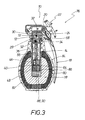
- FIG. 3 shows a hand grenade 76 with a mechano-electrical detonator 10, such as he has been described above in connection with Figures 1 and 2. From Figure 3 it can be seen that the mechano-electric igniter 10 is so small, i.e. has dimensions such that the amplifier charge 48 is virtually in the center of the explosives 78 of a known hand grenade 76.
- the reference number 80 denotes a fragmentation of the hand grenade 76.
- the hand grenade 76 has a lower housing part 82 and an upper housing part 84, that are connected.
- the upper housing part 84 is usually with an upwardly open central part 86 in which the mechano-electrical Igniter 10 is arranged.
- the before the amplifier charge 48 in Central part 86 remaining space 88 can be equipped with a further charge 90 his.
- FIG. 2 also illustrates a shear element 92 by means of which the Flywheel 32 in the inactive idle state, i.e. im through the Securing device 22 secured state of the handle 18, with the Detonator housing 16 or its housing head 12 is releasably connected.
Landscapes
- Engineering & Computer Science (AREA)
- General Engineering & Computer Science (AREA)
- Air Bags (AREA)
- Steering Devices For Bicycles And Motorcycles (AREA)
- Earth Drilling (AREA)
- Window Of Vehicle (AREA)
- Catching Or Destruction (AREA)
- Automotive Seat Belt Assembly (AREA)
Abstract
Description
- Figur 1
- eine Schnittdarstellung des mechano-elektrischen Zünders,
- Figur 2
- eine Schnittdarstellung entlang der Schnittlinie II-II in Figur 1 durch den mechano-elektrischen Zünder, d.h. in einer um 90° gedrehten Schnittebene, und
- Figur 3
- einen Schnitt durch eine mit einem mechano-elektrischen Zünder gemäß den Figuren 1 und 2 versehene Handgranate.
- 10
- Mechano-elektrischer Zünder
- 12
- Gehäusekopf (von 16)
- 14
- Gehäusehülse (von 16)
- 16
- Zündergehäuse
- 18
- Griffbügel (von 10)
- 20
- Bügelachse (für 18)
- 22
- Sicherungseinrichtung (für 16)
- 24
- Spannfeder (zwischen 12 und 18)
- 26
- erster Endabschnitt (von 24 an 12)
- 28
- elektrischer Generator (in 12)
- 30
- Generatorwelle (von 28)
- 32
- Schwungmasse (an 30)
- 34
- Untersetzungsgetriebe (zwischen 30 und 36)
- 36
- Barriereverstellwelle (für 40)
- 38
- Ende (von 36 für 40)
- 40
- Barriere (zwischen 46 und 48)
- 42
- Barrierescheibe (von 40)
- 44
- Barrierescheibe (von 40)
- 46
- Detonator (von 10)
- 48
- Verstärkerladung (von 10)
- 50
- Abteil (in 52 für 46)
- 52
- Schaltungskörper (für 56)
- 54
- Rahmen (von 52)
- 56
- elektronische Zeitverzögerungsschaltung (an 54)
- 58
- Schaltverbindung (zwischen 56 und 46)
- 60
- Schaltungs-Platine (von 56)
- 62
- Schaltungsplatine (von 56)
- 64
- Durchgangsloch (in 42)
- 66
- Durchgangsloch (in 44)
- 68
- Seilzug (zwischen 30 und 18)
- 70
- erstes Ende (von 68 an 30)
- 72
- Windungen (bei 70 an 30)
- 74
- zweites Ende (von 68 an 18)
- 76
- Handgranate
- 78
- Sprengstoff (von 76)
- 80
- Splitterbelegung (von 76)
- 82
- Gehäuseunterteil (von 76)
- 84
- Gehäuseoberteil (von 76)
- 86
- Zentralteil (von 84 für 10)
- 88
- Raum (vor 48 in 86)
- 90
- Ladung (in 88)
- 92
- Scherelement
Claims (10)
- Mechano-elektrischer Zünder für eine Handgranate (76), mit einem Federelement zum Speichern mechanischer Energie, und mit einer mit dem Federelement verbundenen Antriebseinrichtung zum Antrieb eines elektrischen Generators (28) mittels der im Federelement gespeicherten mechanischen Energie, wobei der Generator (28) mit einem Detonator (46) zu dessen Aktivierung zusammengeschaltet ist, den einer Verstärkerladung (48) zugeordnet ist, wobei zwischen dem Detonator (46) und der Verstärkerladung (48) eine Barriere (40) vorgesehen ist,
dadurch gekennzeichnet, daß das Federelement von der zum Griffbügel (18) der Handgranate (76) zugehörigen Spannfeder (24) gebildet ist, und daß die Antriebseinrichtung einen Seilzug (68) aufweist, der mit seinem einen Ende (70) an der Welle (30) des Generators (28) fixiert und mit einer Anzahl Windungen (72) um die Generatorwelle (30) herumgewunden ist, und der mit seinem davon entfernten zweiten Ende (74) am Griffbügel (18) angebracht ist, wobei an der Generatorwelle (30) eine Schwungmasse (32) befestigt ist, die mittels eines Scherelementes (92) im Zündergehäuse (16) freigebbar festgelegt ist. - Mechano-elektrischer Zünder nach Anspruch 1,
dadurch gekennzeichnet, daß der elektrische Generator (28) über eine elektronische Zeitverzögerungsschaltung (56) mit dem Detonator (46) zusammengeschaltet ist. - Mechano-elektrischer Zünder nach Anspruch 2,
dadurch gekennzeichnet, daß die Zeitverzögerung der Zeitverzögerungsschaltung (56) in einem bestimmten Zeitfenster einstellbar ist. - Mechano-elektrischer Zünder nach Anspruch 2 oder 3,
dadurch gekennzeichnet, daß die Zeitverzögerungsschaltung (56) an einem Schaltungskörper (52) vorgesehen ist, der mit einem Abteil (50) ausgebildet ist, in dem der Detonator (46) unbeweglich angeordnet ist. - Mechano-elektrischer Zünder nach Anspruch 4,
dadurch gekennzeichnet, daß die Zeitverzögerungsschaltung (56) an zwei Schaltungs-Platinen (60, 62) ausgebildet ist, und daß der Schaltungskörper (52) einen Rahmen (54) aufweist, an dem die beiden Schaltungs-Platinen (60, 62) voneinander abgewandt und voneinander beabstandet angebracht sind. - Mechano-elektrischer Zünder nach einem der Ansprüche 1 bis 5,
dadurch gekennzeichnet, daß die Generatorwelle (30) mittels eines Untersetzungsgetriebes (34) mit einer Barriereverstellwelle (36) verbunden ist, an deren vom Untersetzungsgetriebe (34) entferntem Ende (38) die Barriere (40) befestigt ist. - Mechano-elektrischer Zünder nach Anspruch 6,
dadurch gekennzeichnet, daß die Barriereverstellwelle (36) sich durch den Schaltungskörper (52) und das Detonator-Abteil (50) zwischen den beiden Schaltungs-Platinen (60 und 62) hindurcherstreckt. - Mechano-elektrischer Zünder nach Anspruch 6,
dadurch gekennzeichnet, daß die Barriere (40) mindestens eine Barrierescheibe aufweist, von der die Barriereverstellwelle (36) mittig wegsteht und die mit einem exzentrisch vorgesehenen Durchgangsloch ausgebildet ist, das in der Scharfstellung der Handgranate (76) mit dem Detonator (46) fluchtet. - Mechano-elektrischer Zünder nach Anspruch 8,
dadurch gekennzeichnet, daß die Barriere (40) zwei konform ausgebildete Barrierescheiben (42 und 44) mit unterschiedlichen Dicken aufweist. - Mechano-elektrischer Zünder nach Anspruch 9,
dadurch gekennzeichnet, daß die dem Detonator (46) zugewandte Barrierescheibe (42) eine größere Wanddicke besitzt als die vom Detonator (46) abgewandte Barrierescheibe (44).
Applications Claiming Priority (2)
| Application Number | Priority Date | Filing Date | Title |
|---|---|---|---|
| DE10316875A DE10316875B4 (de) | 2003-04-11 | 2003-04-11 | Mechano-elektrischer Zünder für eine Handgranate |
| DE10316875 | 2003-04-11 |
Publications (2)
| Publication Number | Publication Date |
|---|---|
| EP1467173A1 true EP1467173A1 (de) | 2004-10-13 |
| EP1467173B1 EP1467173B1 (de) | 2007-11-28 |
Family
ID=32864458
Family Applications (1)
| Application Number | Title | Priority Date | Filing Date |
|---|---|---|---|
| EP04007955A Expired - Lifetime EP1467173B1 (de) | 2003-04-11 | 2004-04-01 | Mechano-elektrischer Zünder für eine Handgranate |
Country Status (5)
| Country | Link |
|---|---|
| US (1) | US7197983B2 (de) |
| EP (1) | EP1467173B1 (de) |
| DE (2) | DE10316875B4 (de) |
| ES (1) | ES2295721T3 (de) |
| NO (1) | NO329370B1 (de) |
Families Citing this family (11)
| Publication number | Priority date | Publication date | Assignee | Title |
|---|---|---|---|---|
| US9234730B1 (en) * | 2007-10-22 | 2016-01-12 | Kendrick Cook | Hand grenade |
| DE102010021685B4 (de) * | 2010-05-27 | 2012-04-12 | Rheinmetall Waffe Munition Gmbh | Wiedersicherung für einen Kipphebelzünder |
| US8561540B1 (en) | 2011-12-29 | 2013-10-22 | The United States Of America As Represented By The Secretary Of The Army | Rotating thumb safety fuze for a hand grenade and related methods of operation and assembly |
| US8887640B1 (en) | 2012-09-10 | 2014-11-18 | The United States Of America As Represented By The Secretary Of The Army | Electro-mechanical fuze for hand grenades |
| US10066915B1 (en) * | 2016-09-21 | 2018-09-04 | The United States Of America As Represented By The Secretary Of The Army | Multi-purpose state changing munition |
| US10088288B1 (en) | 2016-10-06 | 2018-10-02 | The United States Of America As Represented By The Secretary Of The Army | Munition fuze with blast initiated inductance generator for power supply and laser ignitor |
| DE102018128485B4 (de) | 2018-11-14 | 2022-05-05 | Rheinmetall Waffe Munition Gmbh | Elektronische Zündereinheit für einen Irritationskörper und Irritationskörper |
| CN111721165B (zh) * | 2020-05-21 | 2022-04-12 | 重庆致郢科技发展有限公司 | 一种基于电磁阻尼的手雷投掷防误炸辅助装置 |
| RU203366U1 (ru) * | 2020-07-09 | 2021-04-01 | Федеральное государственное казенное военное образовательное учреждение высшего образования "ВОЕННАЯ АКАДЕМИЯ МАТЕРИАЛЬНО-ТЕХНИЧЕСКОГО ОБЕСПЕЧЕНИЯ имени генерала армии А.В. Хрулева" Министерства обороны Российской Федерации | Взрыватель дистанционного подрыва для ручных гранат |
| CN113494871B (zh) * | 2021-07-22 | 2023-08-11 | 中国人民武装警察部队工程大学 | 一种延期时间可切换的手榴弹引信 |
| CN113917905B (zh) * | 2021-09-09 | 2024-06-21 | 华能汕头风力发电有限公司 | 一种升压站辅控系统的综合分析方法 |
Citations (3)
| Publication number | Priority date | Publication date | Assignee | Title |
|---|---|---|---|---|
| AT391026B (de) * | 1988-12-27 | 1990-08-10 | Oregon Ets Patentverwertung | Handgranatenzuender |
| FR2745080A1 (fr) * | 1996-02-21 | 1997-08-22 | Ruggieri | Bouchon allumeur a retard pour engin pyrotechnique |
| US6272995B1 (en) * | 1999-09-14 | 2001-08-14 | Kdi Precision Products, Inc. | High precision fuze for a munition |
Family Cites Families (7)
| Publication number | Priority date | Publication date | Assignee | Title |
|---|---|---|---|---|
| US2282963A (en) * | 1940-08-24 | 1942-05-12 | Rca Corp | Spring driven electric generator |
| US3342998A (en) * | 1965-04-01 | 1967-09-19 | Fidelity Electric Company Inc | Spring-driven electrical generator |
| FR2721394B1 (fr) * | 1994-06-16 | 1996-08-09 | France Etat Armement | Dispositif de mise à feu d'une charge pyrotechnique du type bouchon allumeur notamment pour grenade à main ayant trois modes de fonctionnement. |
| ES2136485B1 (es) * | 1995-12-29 | 2000-05-16 | Instalaza Sa | Espoleta mecano-electronica para granada de mano. |
| US6082267A (en) * | 1997-10-03 | 2000-07-04 | Bulova Technologies, L.L.C. | Electronic, out-of-line safety fuze for munitions such as hand grenades |
| ES2176060B1 (es) * | 1999-10-27 | 2004-02-01 | Instalaza Sa | Mejoras en espoletas mecano-electronicas para granadas de mano. |
| US6707191B1 (en) * | 2003-05-05 | 2004-03-16 | Pontiac Coil, Inc. | Clockspring generator |
-
2003
- 2003-04-11 DE DE10316875A patent/DE10316875B4/de not_active Expired - Fee Related
-
2004
- 2004-04-01 ES ES04007955T patent/ES2295721T3/es not_active Expired - Lifetime
- 2004-04-01 EP EP04007955A patent/EP1467173B1/de not_active Expired - Lifetime
- 2004-04-01 DE DE502004005586T patent/DE502004005586D1/de not_active Expired - Lifetime
- 2004-04-07 NO NO20041466A patent/NO329370B1/no not_active IP Right Cessation
- 2004-04-09 US US10/821,528 patent/US7197983B2/en not_active Expired - Fee Related
Patent Citations (3)
| Publication number | Priority date | Publication date | Assignee | Title |
|---|---|---|---|---|
| AT391026B (de) * | 1988-12-27 | 1990-08-10 | Oregon Ets Patentverwertung | Handgranatenzuender |
| FR2745080A1 (fr) * | 1996-02-21 | 1997-08-22 | Ruggieri | Bouchon allumeur a retard pour engin pyrotechnique |
| US6272995B1 (en) * | 1999-09-14 | 2001-08-14 | Kdi Precision Products, Inc. | High precision fuze for a munition |
Also Published As
| Publication number | Publication date |
|---|---|
| DE502004005586D1 (de) | 2008-01-10 |
| DE10316875A1 (de) | 2004-11-04 |
| NO329370B1 (no) | 2010-10-04 |
| DE10316875A8 (de) | 2005-02-10 |
| EP1467173B1 (de) | 2007-11-28 |
| NO20041466L (no) | 2004-10-12 |
| US20050150414A1 (en) | 2005-07-14 |
| DE10316875B4 (de) | 2005-07-21 |
| US7197983B2 (en) | 2007-04-03 |
| ES2295721T3 (es) | 2008-04-16 |
Similar Documents
| Publication | Publication Date | Title |
|---|---|---|
| EP3274528B1 (de) | Betätigungseinrichtung für ein kraftfahrzeugelektroschloss mit federspeicher | |
| DE19733353C1 (de) | Zündeinrichtung für eine Insassenschutzvorrichtung eines Kraftfahrzeuges | |
| EP1467173B1 (de) | Mechano-elektrischer Zünder für eine Handgranate | |
| CH635673A5 (de) | Elektrisches anzuendelement. | |
| DE3630597A1 (de) | Vorrichtung zur elektromagnetischen verriegelung an einem schliesszylinder fuer ein mechanisch/elektronisches schliess-system | |
| EP0718506A1 (de) | Durch eine Sprengladung verankerbarer Ankerbolzen | |
| DE2215176A1 (de) | Piezoelektrischer Funkenerzeuger | |
| EP1565357A1 (de) | Befestigungsanordnung für einen gurtaufroller | |
| DE2234849A1 (de) | Zuendeinrichtung mit einer ein ungewolltes ausloesen verhindernde sicherungselemente aufweisenden zuendkette | |
| DE1901961C3 (de) | Uhrwerk | |
| EP1906475B1 (de) | Aktivierbare Batterie für elektronischen Artilleriezünder. | |
| DE10000177A1 (de) | Zündeinrichtung, insbesondere für eine Mörsergranate | |
| DE4212454C2 (de) | Zünder | |
| DE2255547A1 (de) | Schalteinrichtung an elektrischen geschosszuendern | |
| DE202012002149U1 (de) | Vorrichtung zum Irritieren von Personen oder Personenansammlungen | |
| DE10133832B4 (de) | Sicherungsvorrichtung für Zünder | |
| DE2047930B2 (de) | Schlagvorrichtung zur qualtitaetskontrolle der verklebung von miteinander verklebten elementen | |
| DE69614816T2 (de) | Mechanisch-elektrischer Zünder für eine Handgranate | |
| DE3402950C2 (de) | ||
| DE1187159B (de) | Entlastungszuender | |
| DE4021319C2 (de) | ||
| DE19514122A1 (de) | Einrichtung zum Zünden oder Sprengen mehrerer Objekte | |
| DE9016841U1 (de) | Kampfmittelräumeinrichtung | |
| DE2553995C3 (de) | Vorrichtung zum Erzeugen piezoelektrischer Energie, insbesondere zur Verwendung bei photographischen Geräten | |
| AT391026B (de) | Handgranatenzuender |
Legal Events
| Date | Code | Title | Description |
|---|---|---|---|
| PUAI | Public reference made under article 153(3) epc to a published international application that has entered the european phase |
Free format text: ORIGINAL CODE: 0009012 |
|
| AK | Designated contracting states |
Kind code of ref document: A1 Designated state(s): AT BE BG CH CY CZ DE DK EE ES FI FR GB GR HU IE IT LI LU MC NL PL PT RO SE SI SK TR |
|
| AX | Request for extension of the european patent |
Extension state: AL HR LT LV MK |
|
| 17P | Request for examination filed |
Effective date: 20040914 |
|
| RAP1 | Party data changed (applicant data changed or rights of an application transferred) |
Owner name: DIEHL BGT DEFENCE GMBH & CO.KG |
|
| AKX | Designation fees paid |
Designated state(s): AT BE BG CH CY CZ DE DK EE ES FI FR GB GR HU IE IT LI LU MC NL PL PT RO SE SI SK TR |
|
| GRAP | Despatch of communication of intention to grant a patent |
Free format text: ORIGINAL CODE: EPIDOSNIGR1 |
|
| GRAS | Grant fee paid |
Free format text: ORIGINAL CODE: EPIDOSNIGR3 |
|
| GRAA | (expected) grant |
Free format text: ORIGINAL CODE: 0009210 |
|
| AK | Designated contracting states |
Kind code of ref document: B1 Designated state(s): AT BE BG CH CY CZ DE DK EE ES FI FR GB GR HU IE IT LI LU MC NL PL PT RO SE SI SK TR |
|
| REG | Reference to a national code |
Ref country code: GB Ref legal event code: FG4D Free format text: NOT ENGLISH |
|
| REG | Reference to a national code |
Ref country code: IE Ref legal event code: FG4D Free format text: LANGUAGE OF EP DOCUMENT: GERMAN |
|
| REG | Reference to a national code |
Ref country code: CH Ref legal event code: EP |
|
| REF | Corresponds to: |
Ref document number: 502004005586 Country of ref document: DE Date of ref document: 20080110 Kind code of ref document: P |
|
| REG | Reference to a national code |
Ref country code: SE Ref legal event code: TRGR |
|
| GBT | Gb: translation of ep patent filed (gb section 77(6)(a)/1977) |
Effective date: 20080207 |
|
| REG | Reference to a national code |
Ref country code: ES Ref legal event code: FG2A Ref document number: 2295721 Country of ref document: ES Kind code of ref document: T3 |
|
| PG25 | Lapsed in a contracting state [announced via postgrant information from national office to epo] |
Ref country code: SI Free format text: LAPSE BECAUSE OF FAILURE TO SUBMIT A TRANSLATION OF THE DESCRIPTION OR TO PAY THE FEE WITHIN THE PRESCRIBED TIME-LIMIT Effective date: 20071128 Ref country code: PL Free format text: LAPSE BECAUSE OF FAILURE TO SUBMIT A TRANSLATION OF THE DESCRIPTION OR TO PAY THE FEE WITHIN THE PRESCRIBED TIME-LIMIT Effective date: 20071128 Ref country code: BG Free format text: LAPSE BECAUSE OF FAILURE TO SUBMIT A TRANSLATION OF THE DESCRIPTION OR TO PAY THE FEE WITHIN THE PRESCRIBED TIME-LIMIT Effective date: 20080228 Ref country code: FI Free format text: LAPSE BECAUSE OF FAILURE TO SUBMIT A TRANSLATION OF THE DESCRIPTION OR TO PAY THE FEE WITHIN THE PRESCRIBED TIME-LIMIT Effective date: 20071128 |
|
| PG25 | Lapsed in a contracting state [announced via postgrant information from national office to epo] |
Ref country code: CZ Free format text: LAPSE BECAUSE OF FAILURE TO SUBMIT A TRANSLATION OF THE DESCRIPTION OR TO PAY THE FEE WITHIN THE PRESCRIBED TIME-LIMIT Effective date: 20071128 Ref country code: DK Free format text: LAPSE BECAUSE OF FAILURE TO SUBMIT A TRANSLATION OF THE DESCRIPTION OR TO PAY THE FEE WITHIN THE PRESCRIBED TIME-LIMIT Effective date: 20071128 |
|
| PG25 | Lapsed in a contracting state [announced via postgrant information from national office to epo] |
Ref country code: SK Free format text: LAPSE BECAUSE OF FAILURE TO SUBMIT A TRANSLATION OF THE DESCRIPTION OR TO PAY THE FEE WITHIN THE PRESCRIBED TIME-LIMIT Effective date: 20071128 Ref country code: RO Free format text: LAPSE BECAUSE OF FAILURE TO SUBMIT A TRANSLATION OF THE DESCRIPTION OR TO PAY THE FEE WITHIN THE PRESCRIBED TIME-LIMIT Effective date: 20071128 |
|
| EN | Fr: translation not filed | ||
| PG25 | Lapsed in a contracting state [announced via postgrant information from national office to epo] |
Ref country code: PT Free format text: LAPSE BECAUSE OF FAILURE TO SUBMIT A TRANSLATION OF THE DESCRIPTION OR TO PAY THE FEE WITHIN THE PRESCRIBED TIME-LIMIT Effective date: 20080428 |
|
| REG | Reference to a national code |
Ref country code: IE Ref legal event code: FD4D |
|
| PLBE | No opposition filed within time limit |
Free format text: ORIGINAL CODE: 0009261 |
|
| STAA | Information on the status of an ep patent application or granted ep patent |
Free format text: STATUS: NO OPPOSITION FILED WITHIN TIME LIMIT |
|
| BERE | Be: lapsed |
Owner name: DIEHL BGT DEFENCE G.M.B.H. & CO.KG Effective date: 20080430 |
|
| PG25 | Lapsed in a contracting state [announced via postgrant information from national office to epo] |
Ref country code: FR Free format text: LAPSE BECAUSE OF FAILURE TO SUBMIT A TRANSLATION OF THE DESCRIPTION OR TO PAY THE FEE WITHIN THE PRESCRIBED TIME-LIMIT Effective date: 20080912 Ref country code: IE Free format text: LAPSE BECAUSE OF FAILURE TO SUBMIT A TRANSLATION OF THE DESCRIPTION OR TO PAY THE FEE WITHIN THE PRESCRIBED TIME-LIMIT Effective date: 20071128 |
|
| 26N | No opposition filed |
Effective date: 20080829 |
|
| PG25 | Lapsed in a contracting state [announced via postgrant information from national office to epo] |
Ref country code: MC Free format text: LAPSE BECAUSE OF NON-PAYMENT OF DUE FEES Effective date: 20080430 |
|
| PG25 | Lapsed in a contracting state [announced via postgrant information from national office to epo] |
Ref country code: GR Free format text: LAPSE BECAUSE OF FAILURE TO SUBMIT A TRANSLATION OF THE DESCRIPTION OR TO PAY THE FEE WITHIN THE PRESCRIBED TIME-LIMIT Effective date: 20080229 Ref country code: EE Free format text: LAPSE BECAUSE OF FAILURE TO SUBMIT A TRANSLATION OF THE DESCRIPTION OR TO PAY THE FEE WITHIN THE PRESCRIBED TIME-LIMIT Effective date: 20071128 |
|
| PG25 | Lapsed in a contracting state [announced via postgrant information from national office to epo] |
Ref country code: BE Free format text: LAPSE BECAUSE OF NON-PAYMENT OF DUE FEES Effective date: 20080430 |
|
| PG25 | Lapsed in a contracting state [announced via postgrant information from national office to epo] |
Ref country code: CY Free format text: LAPSE BECAUSE OF FAILURE TO SUBMIT A TRANSLATION OF THE DESCRIPTION OR TO PAY THE FEE WITHIN THE PRESCRIBED TIME-LIMIT Effective date: 20071128 |
|
| PG25 | Lapsed in a contracting state [announced via postgrant information from national office to epo] |
Ref country code: AT Free format text: LAPSE BECAUSE OF NON-PAYMENT OF DUE FEES Effective date: 20080401 |
|
| PG25 | Lapsed in a contracting state [announced via postgrant information from national office to epo] |
Ref country code: HU Free format text: LAPSE BECAUSE OF FAILURE TO SUBMIT A TRANSLATION OF THE DESCRIPTION OR TO PAY THE FEE WITHIN THE PRESCRIBED TIME-LIMIT Effective date: 20080529 Ref country code: LU Free format text: LAPSE BECAUSE OF NON-PAYMENT OF DUE FEES Effective date: 20080401 |
|
| PG25 | Lapsed in a contracting state [announced via postgrant information from national office to epo] |
Ref country code: TR Free format text: LAPSE BECAUSE OF FAILURE TO SUBMIT A TRANSLATION OF THE DESCRIPTION OR TO PAY THE FEE WITHIN THE PRESCRIBED TIME-LIMIT Effective date: 20071128 |
|
| PGFP | Annual fee paid to national office [announced via postgrant information from national office to epo] |
Ref country code: NL Payment date: 20150420 Year of fee payment: 12 |
|
| PGFP | Annual fee paid to national office [announced via postgrant information from national office to epo] |
Ref country code: CH Payment date: 20150420 Year of fee payment: 12 Ref country code: GB Payment date: 20150420 Year of fee payment: 12 Ref country code: SE Payment date: 20150420 Year of fee payment: 12 Ref country code: DE Payment date: 20150624 Year of fee payment: 12 Ref country code: ES Payment date: 20150427 Year of fee payment: 12 |
|
| PGFP | Annual fee paid to national office [announced via postgrant information from national office to epo] |
Ref country code: IT Payment date: 20150428 Year of fee payment: 12 |
|
| REG | Reference to a national code |
Ref country code: DE Ref legal event code: R119 Ref document number: 502004005586 Country of ref document: DE |
|
| REG | Reference to a national code |
Ref country code: SE Ref legal event code: EUG |
|
| REG | Reference to a national code |
Ref country code: CH Ref legal event code: PL |
|
| REG | Reference to a national code |
Ref country code: NL Ref legal event code: MM Effective date: 20160501 |
|
| GBPC | Gb: european patent ceased through non-payment of renewal fee |
Effective date: 20160401 |
|
| PG25 | Lapsed in a contracting state [announced via postgrant information from national office to epo] |
Ref country code: DE Free format text: LAPSE BECAUSE OF NON-PAYMENT OF DUE FEES Effective date: 20161101 Ref country code: LI Free format text: LAPSE BECAUSE OF NON-PAYMENT OF DUE FEES Effective date: 20160430 Ref country code: NL Free format text: LAPSE BECAUSE OF NON-PAYMENT OF DUE FEES Effective date: 20160501 Ref country code: GB Free format text: LAPSE BECAUSE OF NON-PAYMENT OF DUE FEES Effective date: 20160401 Ref country code: CH Free format text: LAPSE BECAUSE OF NON-PAYMENT OF DUE FEES Effective date: 20160430 |
|
| PG25 | Lapsed in a contracting state [announced via postgrant information from national office to epo] |
Ref country code: IT Free format text: LAPSE BECAUSE OF NON-PAYMENT OF DUE FEES Effective date: 20160401 Ref country code: SE Free format text: LAPSE BECAUSE OF NON-PAYMENT OF DUE FEES Effective date: 20160402 |
|
| PG25 | Lapsed in a contracting state [announced via postgrant information from national office to epo] |
Ref country code: ES Free format text: LAPSE BECAUSE OF NON-PAYMENT OF DUE FEES Effective date: 20160402 |
|
| REG | Reference to a national code |
Ref country code: ES Ref legal event code: FD2A Effective date: 20181205 |