EP1466816A2 - Vorrichtung zur Bedienung eines Spannrads eines Raupenfahrzeugs - Google Patents
Vorrichtung zur Bedienung eines Spannrads eines Raupenfahrzeugs Download PDFInfo
- Publication number
- EP1466816A2 EP1466816A2 EP04006767A EP04006767A EP1466816A2 EP 1466816 A2 EP1466816 A2 EP 1466816A2 EP 04006767 A EP04006767 A EP 04006767A EP 04006767 A EP04006767 A EP 04006767A EP 1466816 A2 EP1466816 A2 EP 1466816A2
- Authority
- EP
- European Patent Office
- Prior art keywords
- rocker arm
- arm
- tension wheel
- hydraulic cylinder
- sleeve
- Prior art date
- Legal status (The legal status is an assumption and is not a legal conclusion. Google has not performed a legal analysis and makes no representation as to the accuracy of the status listed.)
- Granted
Links
Images


Classifications
-
- B—PERFORMING OPERATIONS; TRANSPORTING
- B62—LAND VEHICLES FOR TRAVELLING OTHERWISE THAN ON RAILS
- B62D—MOTOR VEHICLES; TRAILERS
- B62D55/00—Endless track vehicles
- B62D55/08—Endless track units; Parts thereof
- B62D55/30—Track-tensioning means
- B62D55/305—Track-tensioning means acting on pivotably mounted idlers
Definitions
- the present invention relates to a device for manoeuvring a tension wheel in a chassis of a tracked vehicle, in which the tension wheel is rotatably mounted on a free end of a telescopic rocker arm mounted pivotably about a transverse axis in the vehicle, the rocker arm, on the one hand, being able to be lengthened and shortened by means of a first drive mechanism and, on the other hand, being able to be swivelled about the transverse axis by means of a second drive mechanism for the purpose of raising and lowering the tension wheel.
- a first of the cylinders forms a telescopic rocker arm for the tension wheel and the second forms a manoeuvring cylinder for swivelling the first cylinder.
- the first cylinder is pivotably mounted at a point which lies closer to the lower than to the upper running part of the crawler track of the vehicle, meaning that the tension wheel, when the first cylinder is swivelled down, automatically stretches the crawler track somewhat.
- the device according to the invention is characterized in that the first drive mechanism is designed to be able to rotate a sleeve rotatable about the transverse axis in a hub part of an inner part of the rocker arm, which sleeve has an eccentrically mounted crank pin which is hinge-connected to an outer part of the rocker arm for the purpose of displacing the latter relative to the inner arm part, in the event of a mutual rotation motion between the sleeve and the hub part of the inner rocker arm part, in such a way that the rocker arm is lengthened upon a downward swivel motion of the arm and the tension wheel by courtesy of the second drive mechanism.
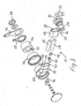
- a tension wheel station on a rear portion of a tracked vehicle is denoted by 10.
- the tension wheel station 10 comprises a telescopic rocker arm 12, which is pivotably mounted about a transverse axis 14 in a frame or a rigid hull 16 of the vehicle.
- the rocker arm 12 has an inner arm part 18 having a hub portion 20 (Fig. 3), which is rotatably mounted in the hull 16, and an outer arm part 22 mounted displaceably in the inner part 18.
- the outer arm part 22 supports on its outer end an axle journal 24 (Fig. 3) for a tension wheel hub 26, in which a track tension wheel (not shown) can be mounted.
- the rocker arm 12 has an oblong cross section in the vertical direction for increased rigidity in the swivel plane and comprises a lower connecting rod 28, which is fastened in a rear portion 30 of the axle journal 24 with the aid of a locking plate 32.
- a guide rod 34 situated above the connecting rod 28 is likewise fastened in the portion 30 of the axle journal 24 by means of the locking plate 32.
- the two rods 28, 34 extend through respective ducts 36, 38 in the frame part 40 of the outer arm part 22 and slidably through corresponding ducts 42, 44 in a frame part 46 of the inner arm part 18.
- the lower connecting rod 28 has, on its inner end, a lug 48, in which a link 50 is hinge-fastened.
- the other, inner end of the link 50 is hinge-connected to an eccentric pin 52, directed parallel with the transverse axis 14, on a sleeve 54 rotatable in the hub portion 20.
- the hub portion 20 is, in turn, rotatably mounted in a housing 56 mounted in a rotationally secure manner in the frame 16.
- Connected in a rotationally secure manner to the sleeve 54 is a lever arm 58.
- a piston rod 60 (Figs. 1 and 2) of a first hydraulic cylinder 62 is hinge-connected to the lever arm 58 so as, when the piston rod 60 is thrust into the cylinder 62, to rotate the eccentric sleeve 54 in the hub portion 20 and hence displace the outer arm part 22 into the inner arm part 18 through the agency of the lower connecting rod 28.
- the cylinder 62 is hinge-fastened in a hull-fixed part of the vehicle by way of a pivot pin 66.
- the outer arm part 22 can be retracted from the inner arm part 18 when the piston rod 60 is retracted from the cylinder 62, in order thereby to produce an extension of the rocker arm and hence a stretching of a crawler track (not shown) of the vehicle, running around the tension wheel (likewise not shown).
- a second hydraulic cylinder 64 situated above and essentially parallel with the first hydraulic cylinder 62, is hinge-connected on its rear end to a hull-fixed part of the vehicle.
- a piston rod 68 of the second cylinder 64 is hinge-connected to a further lever arm 70, which is connected in a rotationally secure manner to the hub portion 20 of the inner arm part 18, so as, when the piston rod 68 is thrust into the cylinder 64, to swivel the rocker arm 12 in a swivel direction downward about the transverse axis 14 from the swivelled-up position shown in Fig. 1 to the swivelled-down position shown in Fig. 2.
- the upper, second hydraulic cylinder 64 is configured so as, when the rocker arm 12 is swivelled down (Fig. 2), to form a shock absorber to allow spring deflection motions of the tension wheel, the oil in the cylinder 64 being able to be allowed to flow through a constriction (not shown) and, at high inward deflection or outward deflection velocity, also through a pressure limiter (not shown).
- the cylinder 64 In a swivelled-up position of the rocker arm 12 (Fig. 1), the cylinder 64, on the other hand, is hydraulically locked so as to prohibit any swivel motion of the rocker arm 12.
- a tension wheel station 10 is disposed on each side of the rear portion of the tracked vehicle.
- Each rocker arm 12 is further sprung by means of a respective torsion bar 72, 74, one end of which is fastened in an anchor 76 (Fig. 3) in the one tension wheel station 10 and the other end of which is connected to the opposite side of the hull 16 by an anchor 78 in the opposing tension wheel station 10 (Fig. 3).
- the torsion bars 72, 74 are rotated fully one degree in relation to the transverse direction of the vehicle to prevent them from colliding with each other.
- a supporting wheel 82 is designed to support an upper running part of the crawler track (not shown).
- the rocker arm 12 With the first hydraulic cylinder 62, the rocker arm 12, irrespective of its position, can be shortened in order to make it easier for a crawler track to be slipped on and taken off. Further, the track tension can be base-set to a desired value with the aid of the cylinder 62. After this, the cylinder 62 is locked in its position. With the hydraulic cylinder 64, the position of the rocker arm 12 and of the tension wheel is reset to either a swivelled-up position for best driving and track wear behaviour when travelling on a firm surface, or a swivelled-down position for optimal handling on a soft surface, such as snow, swamps and the like.
- hydraulic cylinders 62 and 64 have been shown as the drive mechanisms for influencing the length and angular position of the rocker arm 12, it is possible, of course, within the scope of the inventive concept, to utilize other linear or rotary drive mechanisms to produce an equivalent manoeuvring function.
- pneumatic cylinders, ball screws, electric or hydraulic motors with gear transmissions and the like would be conceivable.
Landscapes
- Engineering & Computer Science (AREA)
- Combustion & Propulsion (AREA)
- Transportation (AREA)
- Mechanical Engineering (AREA)
- Chemical & Material Sciences (AREA)
- Vehicle Body Suspensions (AREA)
- Devices For Conveying Motion By Means Of Endless Flexible Members (AREA)
- Transmissions By Endless Flexible Members (AREA)
- Automatic Cycles, And Cycles In General (AREA)
- Valve-Gear Or Valve Arrangements (AREA)
- Motorcycle And Bicycle Frame (AREA)
- Automobile Manufacture Line, Endless Track Vehicle, Trailer (AREA)
- Forklifts And Lifting Vehicles (AREA)
Priority Applications (1)
| Application Number | Priority Date | Filing Date | Title |
|---|---|---|---|
| PL04006767T PL1466816T3 (pl) | 2003-04-09 | 2004-03-20 | Urządzenie do manewrowania kołem naciągowym pojazdu gąsienicowego |
Applications Claiming Priority (2)
| Application Number | Priority Date | Filing Date | Title |
|---|---|---|---|
| SE0301046A SE525073C2 (sv) | 2003-04-09 | 2003-04-09 | Anordning för manövrering av ett spännhjul hos ett bandfordon |
| SE0301046 | 2003-04-09 |
Publications (3)
| Publication Number | Publication Date |
|---|---|
| EP1466816A2 true EP1466816A2 (de) | 2004-10-13 |
| EP1466816A3 EP1466816A3 (de) | 2005-06-22 |
| EP1466816B1 EP1466816B1 (de) | 2006-09-20 |
Family
ID=20290975
Family Applications (1)
| Application Number | Title | Priority Date | Filing Date |
|---|---|---|---|
| EP04006767A Expired - Lifetime EP1466816B1 (de) | 2003-04-09 | 2004-03-20 | Vorrichtung zur Bedienung eines Spannrads eines Raupenfahrzeugs |
Country Status (9)
| Country | Link |
|---|---|
| US (1) | US7093914B2 (de) |
| EP (1) | EP1466816B1 (de) |
| AT (1) | ATE340123T1 (de) |
| DE (1) | DE602004002424T2 (de) |
| ES (1) | ES2273111T3 (de) |
| NO (1) | NO325968B1 (de) |
| PL (1) | PL1466816T3 (de) |
| SE (1) | SE525073C2 (de) |
| SG (1) | SG115650A1 (de) |
Cited By (2)
| Publication number | Priority date | Publication date | Assignee | Title |
|---|---|---|---|---|
| EP1818244A3 (de) * | 2006-02-08 | 2008-06-25 | BAE Systems Hägglunds Aktiebolag | Verfahren zum Betrieb eines Kettenspannungsrads |
| WO2010071552A1 (en) * | 2008-12-16 | 2010-06-24 | BAE Systems Hägglunds Aktiebolag | Arrangement for controlling a track tension wheel of a tracked vehicle |
Families Citing this family (1)
| Publication number | Priority date | Publication date | Assignee | Title |
|---|---|---|---|---|
| CN110194226B (zh) * | 2019-07-12 | 2024-08-30 | 江苏徐工工程机械研究院有限公司 | 车辆履带装置和车辆 |
Family Cites Families (10)
| Publication number | Priority date | Publication date | Assignee | Title |
|---|---|---|---|---|
| US2843431A (en) * | 1956-12-28 | 1958-07-15 | John M Beaufort | Hydraulic track tensioning device |
| DK103654A (de) * | 1960-11-26 | |||
| SU383645A1 (ru) * | 1971-01-25 | 1973-05-23 | Свердловский научно исследовательский институт лесной промышленности | Подвеска направляющего колеса гусеничного шасси транспортного средства |
| DE2521145C3 (de) * | 1975-05-13 | 1979-08-09 | Dr.Ing.H.C. F. Porsche Ag, 7000 Stuttgart | Verstellvorrichtung für Laufräder von Gleiskettenfahrzeugen |
| SU677979A1 (ru) * | 1978-02-13 | 1979-08-05 | Онежский Ордена Ленина И Октябрьской Революции Тракторный Завод | Ходова часть гусеничной машины |
| SU806517A1 (ru) * | 1979-03-28 | 1981-02-23 | Онежский Ордена Ленина И Орденаоктябрьской Революции Тракторныйзавод | Подвеска направл ющего колесагуСЕНичНОй МАшиНы |
| SE468939B (sv) * | 1989-10-23 | 1993-04-19 | Haegglunds Vehicle Ab | Bandstaell foer bandfordon |
| US5316381A (en) * | 1992-11-13 | 1994-05-31 | Deere & Company | Tensioning and suspension system for a tracked vehicle |
| SE508171C2 (sv) * | 1997-10-03 | 1998-09-07 | Haegglunds Vehicle Ab | Bandspänningsanordning för banddrivet motorfodon |
| US6273530B1 (en) * | 2000-01-06 | 2001-08-14 | Deere & Company | Toe-in/toe-out adjustment mechanism |
-
2003
- 2003-04-09 SE SE0301046A patent/SE525073C2/sv not_active IP Right Cessation
-
2004
- 2004-03-19 SG SG200401635A patent/SG115650A1/en unknown
- 2004-03-20 ES ES04006767T patent/ES2273111T3/es not_active Expired - Lifetime
- 2004-03-20 EP EP04006767A patent/EP1466816B1/de not_active Expired - Lifetime
- 2004-03-20 DE DE602004002424T patent/DE602004002424T2/de not_active Expired - Lifetime
- 2004-03-20 PL PL04006767T patent/PL1466816T3/pl unknown
- 2004-03-20 AT AT04006767T patent/ATE340123T1/de active
- 2004-04-01 NO NO20041358A patent/NO325968B1/no not_active IP Right Cessation
- 2004-04-07 US US10/819,115 patent/US7093914B2/en not_active Expired - Fee Related
Cited By (4)
| Publication number | Priority date | Publication date | Assignee | Title |
|---|---|---|---|---|
| EP1818244A3 (de) * | 2006-02-08 | 2008-06-25 | BAE Systems Hägglunds Aktiebolag | Verfahren zum Betrieb eines Kettenspannungsrads |
| US7597411B2 (en) | 2006-02-08 | 2009-10-06 | BAE Systems Hägglunds Aktiebolag | Device for operating a track tension wheel |
| WO2010071552A1 (en) * | 2008-12-16 | 2010-06-24 | BAE Systems Hägglunds Aktiebolag | Arrangement for controlling a track tension wheel of a tracked vehicle |
| US8708431B2 (en) | 2008-12-16 | 2014-04-29 | BAE Systems Hägglunds Aktiebolag | Arrangement for controlling a track tension wheel of tracked vehicle |
Also Published As
| Publication number | Publication date |
|---|---|
| SE0301046L (sv) | 2004-10-10 |
| SE525073C2 (sv) | 2004-11-23 |
| SE0301046D0 (sv) | 2003-04-09 |
| ATE340123T1 (de) | 2006-10-15 |
| EP1466816A3 (de) | 2005-06-22 |
| PL1466816T3 (pl) | 2007-01-31 |
| NO20041358L (no) | 2004-10-11 |
| EP1466816B1 (de) | 2006-09-20 |
| DE602004002424T2 (de) | 2007-02-01 |
| US20040207258A1 (en) | 2004-10-21 |
| SG115650A1 (en) | 2005-10-28 |
| DE602004002424D1 (de) | 2006-11-02 |
| US7093914B2 (en) | 2006-08-22 |
| NO325968B1 (no) | 2008-08-25 |
| ES2273111T3 (es) | 2007-05-01 |
Similar Documents
| Publication | Publication Date | Title |
|---|---|---|
| DE60113560T2 (de) | Aufhängungsanordnung | |
| US10202154B2 (en) | Suspension and lock-out systems for a partially tracked vehicle | |
| DE69517684T2 (de) | Rad-aufhängungssystem | |
| US6116362A (en) | Articulated vehicle | |
| US7077220B2 (en) | Tractor with rear castor wheels | |
| RU2126331C1 (ru) | Механизм регулирования наклона (варианты) и транспортное средство (варианты) | |
| JP2609470B2 (ja) | 履帯型車両のサスペンション構造 | |
| CN108100066B (zh) | 一种可调整履带行走机构及拖拉机 | |
| AU2002249471B2 (en) | Vehicle with retractable wheel | |
| US8708431B2 (en) | Arrangement for controlling a track tension wheel of tracked vehicle | |
| JP2004506564A (ja) | 懸架システム | |
| AU2002249471A1 (en) | Vehicle with retractable wheel | |
| EP0390787A1 (de) | Land- oder bauwirtschaftlich nutzbarer schlepper mit einer lenkbaren starrachse. | |
| DE102006004959B4 (de) | Radaufhängung für ein Kraftfahrzeug | |
| EP1466816B1 (de) | Vorrichtung zur Bedienung eines Spannrads eines Raupenfahrzeugs | |
| US10434833B1 (en) | Rotary cutter with torsional suspension system | |
| US7597411B2 (en) | Device for operating a track tension wheel | |
| EP0761481B1 (de) | Achse eines land- oder bauwirtschaftlichen Fahrzeuges | |
| CN111661182A (zh) | 三角履带轮和工程车辆 | |
| DE102006012640A1 (de) | Aufhängevorrichtung vom Schwenkarmtyp eines Fahrzeugs | |
| CA2129851A1 (en) | Vehicle with retractable wheel | |
| DE10062565A1 (de) | Flurförderzeug mit einer federnd aufgehängten Antriebsachse | |
| DE60307347T2 (de) | Einzelaufhängung für ein Rad eines Nutzfahrzeugs | |
| SU895785A1 (ru) | Устройство подвески направл ющего колеса гусеничного транспортного средства | |
| EP1253103B1 (de) | Flurförderzeug mit einer federnd aufgehängten Lenkachse |
Legal Events
| Date | Code | Title | Description |
|---|---|---|---|
| PUAI | Public reference made under article 153(3) epc to a published international application that has entered the european phase |
Free format text: ORIGINAL CODE: 0009012 |
|
| AK | Designated contracting states |
Kind code of ref document: A2 Designated state(s): AT BE BG CH CY CZ DE DK EE ES FI FR GB GR HU IE IT LI LU MC NL PL PT RO SE SI SK TR |
|
| AX | Request for extension of the european patent |
Extension state: AL LT LV MK |
|
| PUAL | Search report despatched |
Free format text: ORIGINAL CODE: 0009013 |
|
| AK | Designated contracting states |
Kind code of ref document: A3 Designated state(s): AT BE BG CH CY CZ DE DK EE ES FI FR GB GR HU IE IT LI LU MC NL PL PT RO SE SI SK TR |
|
| AX | Request for extension of the european patent |
Extension state: AL LT LV MK |
|
| 17P | Request for examination filed |
Effective date: 20051122 |
|
| RAP1 | Party data changed (applicant data changed or rights of an application transferred) |
Owner name: LAND SYSTEMS HAEGGLUNDS AKTIEBOLAG |
|
| GRAP | Despatch of communication of intention to grant a patent |
Free format text: ORIGINAL CODE: EPIDOSNIGR1 |
|
| AKX | Designation fees paid |
Designated state(s): AT BE BG CH CY CZ DE DK EE ES FI FR GB GR HU IE IT LI LU MC NL PL PT RO SE SI SK TR |
|
| GRAS | Grant fee paid |
Free format text: ORIGINAL CODE: EPIDOSNIGR3 |
|
| RAP1 | Party data changed (applicant data changed or rights of an application transferred) |
Owner name: BAE SYSTEMS HAEGGLUNDS AKTIEBOLAG |
|
| GRAA | (expected) grant |
Free format text: ORIGINAL CODE: 0009210 |
|
| AK | Designated contracting states |
Kind code of ref document: B1 Designated state(s): AT BE BG CH CY CZ DE DK EE ES FI FR GB GR HU IE IT LI LU MC NL PL PT RO SE SI SK TR |
|
| PG25 | Lapsed in a contracting state [announced via postgrant information from national office to epo] |
Ref country code: NL Free format text: LAPSE BECAUSE OF FAILURE TO SUBMIT A TRANSLATION OF THE DESCRIPTION OR TO PAY THE FEE WITHIN THE PRESCRIBED TIME-LIMIT Effective date: 20060920 Ref country code: IT Free format text: LAPSE BECAUSE OF FAILURE TO SUBMIT A TRANSLATION OF THE DESCRIPTION OR TO PAY THE FEE WITHIN THE PRESCRIBED TIME-LIMIT;WARNING: LAPSES OF ITALIAN PATENTS WITH EFFECTIVE DATE BEFORE 2007 MAY HAVE OCCURRED AT ANY TIME BEFORE 2007. THE CORRECT EFFECTIVE DATE MAY BE DIFFERENT FROM THE ONE RECORDED. Effective date: 20060920 Ref country code: RO Free format text: LAPSE BECAUSE OF FAILURE TO SUBMIT A TRANSLATION OF THE DESCRIPTION OR TO PAY THE FEE WITHIN THE PRESCRIBED TIME-LIMIT Effective date: 20060920 Ref country code: SI Free format text: LAPSE BECAUSE OF FAILURE TO SUBMIT A TRANSLATION OF THE DESCRIPTION OR TO PAY THE FEE WITHIN THE PRESCRIBED TIME-LIMIT Effective date: 20060920 |
|
| REG | Reference to a national code |
Ref country code: GB Ref legal event code: FG4D |
|
| REG | Reference to a national code |
Ref country code: CH Ref legal event code: EP |
|
| REG | Reference to a national code |
Ref country code: CH Ref legal event code: NV Representative=s name: BOVARD AG PATENTANWAELTE |
|
| REG | Reference to a national code |
Ref country code: IE Ref legal event code: FG4D |
|
| REF | Corresponds to: |
Ref document number: 602004002424 Country of ref document: DE Date of ref document: 20061102 Kind code of ref document: P |
|
| PG25 | Lapsed in a contracting state [announced via postgrant information from national office to epo] |
Ref country code: SE Free format text: LAPSE BECAUSE OF FAILURE TO SUBMIT A TRANSLATION OF THE DESCRIPTION OR TO PAY THE FEE WITHIN THE PRESCRIBED TIME-LIMIT Effective date: 20061220 Ref country code: BG Free format text: LAPSE BECAUSE OF FAILURE TO SUBMIT A TRANSLATION OF THE DESCRIPTION OR TO PAY THE FEE WITHIN THE PRESCRIBED TIME-LIMIT Effective date: 20061220 Ref country code: DK Free format text: LAPSE BECAUSE OF FAILURE TO SUBMIT A TRANSLATION OF THE DESCRIPTION OR TO PAY THE FEE WITHIN THE PRESCRIBED TIME-LIMIT Effective date: 20061220 |
|
| REG | Reference to a national code |
Ref country code: PL Ref legal event code: T3 |
|
| NLV1 | Nl: lapsed or annulled due to failure to fulfill the requirements of art. 29p and 29m of the patents act | ||
| PG25 | Lapsed in a contracting state [announced via postgrant information from national office to epo] |
Ref country code: PT Free format text: LAPSE BECAUSE OF FAILURE TO SUBMIT A TRANSLATION OF THE DESCRIPTION OR TO PAY THE FEE WITHIN THE PRESCRIBED TIME-LIMIT Effective date: 20070312 |
|
| ET | Fr: translation filed | ||
| REG | Reference to a national code |
Ref country code: ES Ref legal event code: FG2A Ref document number: 2273111 Country of ref document: ES Kind code of ref document: T3 |
|
| PLBE | No opposition filed within time limit |
Free format text: ORIGINAL CODE: 0009261 |
|
| STAA | Information on the status of an ep patent application or granted ep patent |
Free format text: STATUS: NO OPPOSITION FILED WITHIN TIME LIMIT |
|
| 26N | No opposition filed |
Effective date: 20070621 |
|
| PG25 | Lapsed in a contracting state [announced via postgrant information from national office to epo] |
Ref country code: MC Free format text: LAPSE BECAUSE OF NON-PAYMENT OF DUE FEES Effective date: 20070331 Ref country code: IE Free format text: LAPSE BECAUSE OF NON-PAYMENT OF DUE FEES Effective date: 20070320 |
|
| PG25 | Lapsed in a contracting state [announced via postgrant information from national office to epo] |
Ref country code: GR Free format text: LAPSE BECAUSE OF FAILURE TO SUBMIT A TRANSLATION OF THE DESCRIPTION OR TO PAY THE FEE WITHIN THE PRESCRIBED TIME-LIMIT Effective date: 20061221 |
|
| PG25 | Lapsed in a contracting state [announced via postgrant information from national office to epo] |
Ref country code: EE Free format text: LAPSE BECAUSE OF FAILURE TO SUBMIT A TRANSLATION OF THE DESCRIPTION OR TO PAY THE FEE WITHIN THE PRESCRIBED TIME-LIMIT Effective date: 20060920 |
|
| PGRI | Patent reinstated in contracting state [announced from national office to epo] |
Ref country code: IT Effective date: 20080601 |
|
| PG25 | Lapsed in a contracting state [announced via postgrant information from national office to epo] |
Ref country code: CY Free format text: LAPSE BECAUSE OF FAILURE TO SUBMIT A TRANSLATION OF THE DESCRIPTION OR TO PAY THE FEE WITHIN THE PRESCRIBED TIME-LIMIT Effective date: 20060920 Ref country code: LU Free format text: LAPSE BECAUSE OF NON-PAYMENT OF DUE FEES Effective date: 20070320 |
|
| PG25 | Lapsed in a contracting state [announced via postgrant information from national office to epo] |
Ref country code: HU Free format text: LAPSE BECAUSE OF FAILURE TO SUBMIT A TRANSLATION OF THE DESCRIPTION OR TO PAY THE FEE WITHIN THE PRESCRIBED TIME-LIMIT Effective date: 20070321 |
|
| PGFP | Annual fee paid to national office [announced via postgrant information from national office to epo] |
Ref country code: FI Payment date: 20110321 Year of fee payment: 8 Ref country code: PL Payment date: 20110308 Year of fee payment: 8 Ref country code: SK Payment date: 20110321 Year of fee payment: 8 Ref country code: TR Payment date: 20110317 Year of fee payment: 8 Ref country code: AT Payment date: 20110330 Year of fee payment: 8 Ref country code: CZ Payment date: 20110317 Year of fee payment: 8 Ref country code: CH Payment date: 20110316 Year of fee payment: 8 |
|
| PGFP | Annual fee paid to national office [announced via postgrant information from national office to epo] |
Ref country code: DE Payment date: 20110325 Year of fee payment: 8 Ref country code: FR Payment date: 20110408 Year of fee payment: 8 Ref country code: ES Payment date: 20110323 Year of fee payment: 8 Ref country code: BE Payment date: 20110323 Year of fee payment: 8 Ref country code: GB Payment date: 20110325 Year of fee payment: 8 |
|
| PGFP | Annual fee paid to national office [announced via postgrant information from national office to epo] |
Ref country code: IT Payment date: 20110328 Year of fee payment: 8 |
|
| BERE | Be: lapsed |
Owner name: *BAE SYSTEMS HAGGLUNDS A.B. Effective date: 20120331 |
|
| PG25 | Lapsed in a contracting state [announced via postgrant information from national office to epo] |
Ref country code: CZ Free format text: LAPSE BECAUSE OF NON-PAYMENT OF DUE FEES Effective date: 20120320 Ref country code: FI Free format text: LAPSE BECAUSE OF NON-PAYMENT OF DUE FEES Effective date: 20120320 |
|
| REG | Reference to a national code |
Ref country code: CH Ref legal event code: PL |
|
| GBPC | Gb: european patent ceased through non-payment of renewal fee |
Effective date: 20120320 |
|
| REG | Reference to a national code |
Ref country code: SK Ref legal event code: MM4A Ref document number: E 1294 Country of ref document: SK Effective date: 20120320 |
|
| REG | Reference to a national code |
Ref country code: AT Ref legal event code: MM01 Ref document number: 340123 Country of ref document: AT Kind code of ref document: T Effective date: 20120320 |
|
| REG | Reference to a national code |
Ref country code: FR Ref legal event code: ST Effective date: 20121130 |
|
| REG | Reference to a national code |
Ref country code: DE Ref legal event code: R119 Ref document number: 602004002424 Country of ref document: DE Effective date: 20121002 |
|
| PG25 | Lapsed in a contracting state [announced via postgrant information from national office to epo] |
Ref country code: GB Free format text: LAPSE BECAUSE OF NON-PAYMENT OF DUE FEES Effective date: 20120320 Ref country code: AT Free format text: LAPSE BECAUSE OF NON-PAYMENT OF DUE FEES Effective date: 20120320 Ref country code: FR Free format text: LAPSE BECAUSE OF NON-PAYMENT OF DUE FEES Effective date: 20120402 Ref country code: CH Free format text: LAPSE BECAUSE OF NON-PAYMENT OF DUE FEES Effective date: 20120331 Ref country code: BE Free format text: LAPSE BECAUSE OF NON-PAYMENT OF DUE FEES Effective date: 20120331 Ref country code: LI Free format text: LAPSE BECAUSE OF NON-PAYMENT OF DUE FEES Effective date: 20120331 Ref country code: SK Free format text: LAPSE BECAUSE OF NON-PAYMENT OF DUE FEES Effective date: 20120320 |
|
| PG25 | Lapsed in a contracting state [announced via postgrant information from national office to epo] |
Ref country code: IT Free format text: LAPSE BECAUSE OF FAILURE TO SUBMIT A TRANSLATION OF THE DESCRIPTION OR TO PAY THE FEE WITHIN THE PRESCRIBED TIME-LIMIT Effective date: 20120320 |
|
| PG25 | Lapsed in a contracting state [announced via postgrant information from national office to epo] |
Ref country code: PL Free format text: LAPSE BECAUSE OF NON-PAYMENT OF DUE FEES Effective date: 20120320 |
|
| REG | Reference to a national code |
Ref country code: PL Ref legal event code: LAPE |
|
| REG | Reference to a national code |
Ref country code: ES Ref legal event code: FD2A Effective date: 20130710 |
|
| PG25 | Lapsed in a contracting state [announced via postgrant information from national office to epo] |
Ref country code: ES Free format text: LAPSE BECAUSE OF NON-PAYMENT OF DUE FEES Effective date: 20120321 |
|
| PG25 | Lapsed in a contracting state [announced via postgrant information from national office to epo] |
Ref country code: TR Free format text: LAPSE BECAUSE OF NON-PAYMENT OF DUE FEES Effective date: 20120320 |
|
| PG25 | Lapsed in a contracting state [announced via postgrant information from national office to epo] |
Ref country code: DE Free format text: LAPSE BECAUSE OF NON-PAYMENT OF DUE FEES Effective date: 20121002 |