EP1466542A2 - Device for the application of a line - Google Patents
Device for the application of a line Download PDFInfo
- Publication number
- EP1466542A2 EP1466542A2 EP04290975A EP04290975A EP1466542A2 EP 1466542 A2 EP1466542 A2 EP 1466542A2 EP 04290975 A EP04290975 A EP 04290975A EP 04290975 A EP04290975 A EP 04290975A EP 1466542 A2 EP1466542 A2 EP 1466542A2
- Authority
- EP
- European Patent Office
- Prior art keywords
- arms
- gripping member
- assembly according
- application
- reservoir
- Prior art date
- Legal status (The legal status is an assumption and is not a legal conclusion. Google has not performed a legal analysis and makes no representation as to the accuracy of the status listed.)
- Granted
Links
Images
Classifications
-
- B—PERFORMING OPERATIONS; TRANSPORTING
- B43—WRITING OR DRAWING IMPLEMENTS; BUREAU ACCESSORIES
- B43L—ARTICLES FOR WRITING OR DRAWING UPON; WRITING OR DRAWING AIDS; ACCESSORIES FOR WRITING OR DRAWING
- B43L25/00—Ink receptacles
- B43L25/007—Portable ink receptacles; Filling devices for receptacles
-
- A—HUMAN NECESSITIES
- A45—HAND OR TRAVELLING ARTICLES
- A45D—HAIRDRESSING OR SHAVING EQUIPMENT; EQUIPMENT FOR COSMETICS OR COSMETIC TREATMENTS, e.g. FOR MANICURING OR PEDICURING
- A45D40/00—Casings or accessories specially adapted for storing or handling solid or pasty toiletry or cosmetic substances, e.g. shaving soaps or lipsticks
- A45D40/26—Appliances specially adapted for applying pasty paint, e.g. using roller, using a ball
-
- B—PERFORMING OPERATIONS; TRANSPORTING
- B43—WRITING OR DRAWING IMPLEMENTS; BUREAU ACCESSORIES
- B43L—ARTICLES FOR WRITING OR DRAWING UPON; WRITING OR DRAWING AIDS; ACCESSORIES FOR WRITING OR DRAWING
- B43L25/00—Ink receptacles
- B43L25/10—Ink receptacles with means for holding objects
-
- A—HUMAN NECESSITIES
- A45—HAND OR TRAVELLING ARTICLES
- A45D—HAIRDRESSING OR SHAVING EQUIPMENT; EQUIPMENT FOR COSMETICS OR COSMETIC TREATMENTS, e.g. FOR MANICURING OR PEDICURING
- A45D2200/00—Details not otherwise provided for in A45D
- A45D2200/10—Details of applicators
- A45D2200/1072—Eyeliners
Landscapes
- Coating Apparatus (AREA)
- Vehicle Body Suspensions (AREA)
- Massaging Devices (AREA)
- Compression-Type Refrigeration Machines With Reversible Cycles (AREA)
- Media Introduction/Drainage Providing Device (AREA)
- Electric Cable Installation (AREA)
- Electrical Discharge Machining, Electrochemical Machining, And Combined Machining (AREA)
Abstract
Description
La présente invention a pour objet un dispositif d'application d'un trait, notamment pour réaliser un trait à partir d'un produit cosmétique sur une surface à enduire. L'invention a en particulier un intérêt dans le domaine des applicateurs cosmétiques tels que des ligneurs, également appelés "eyeliners", prévus pour la réalisation d'un trait continu ou discontinu à la bordure des paupières. Le trait appliqué est destiné à souligner le contour des yeux, à en modifier leur ligne et leur dimension.The subject of the present invention is a device for applying a stroke, especially to make a line from a cosmetic product on a surface to coated. The invention is in particular of interest in the field of applicators cosmetics such as liners, also called "eyeliners", intended for the realization of a continuous or discontinuous line at the edge of the eyelids. The line applied is intended to emphasize the eye contour, to modify their line and their dimension.
Des dispositifs d'application selon l'invention permettent une application fine et précise d'un tel trait continu, l'application pouvant être réalisée d'une seule main et en particulier en ne nécessitant pas l'utilisation d'un miroir pour contrôler l'application. En effet, la gestuelle associée au dispositif de l'invention permet d'enduire le contour d'une paupière, avec certitude, sur une longueur définie et en contrôlant le point de départ du trait. L'application peut être réalisée dans des conditions où l'utilisateur est soumis à des secousses, par exemple dans un moyen de transport, car cette application peut se faire en gardant en permanence un point d'appui fixe sur la paupière.Application devices according to the invention allow fine application and precise with such a continuous line, the application being able to be carried out with one hand and in particular by not requiring the use of a mirror to control the application. Indeed, the gestures associated with the device of the invention allows to coat the contour of an eyelid, with certainty, over a defined length and controlling the starting point of the line. The application can be carried out in conditions where the user is shaken, for example in a means of transport, because this application can be done by keeping permanently a fixed fulcrum on the eyelid.
Dans l'état de la technique, on connaít des "eyeliners" tels que l'applicateur, en forme de pointe, est monté au bout d'une tige fixée dans un capot, et ce capot est prévu pour être monté sur un réservoir de produit de manière à ce que l'applicateur soit immergé dans le produit dans une position assemblée du capot sur le réservoir. Ensuite, l'utilisatrice qui veut dessiner un trait à la bordure de sa paupière doit déplacer régulièrement la pointe de l'applicateur le long de la surface à enduire. Cette opération de maquillage est difficile à réaliser sans ratures. Le trait obtenu comporte souvent des décrochements non souhaités.In the state of the art, we know "eyeliners" such as the applicator, in the shape of a point, is mounted at the end of a rod fixed in a cover, and this cover is intended to be mounted on a product tank so that the applicator is immersed in the product in an assembled position of the cover on the tank. Then, the user who wants to draw a line around the border of her eyelid should regularly move the tip of the applicator along the surface to coat. This makeup operation is difficult to carry out without erasures. The trait obtained often involves unwanted dropouts.
Ainsi il est connu du document US-3,343,552, d'utiliser un applicateur préformé de manière à être parfaitement adapté à la surface sur laquelle il doit être appliqué. Le maquillage des yeux tel qu'enseigné par ce document, n'est pas adaptable. L'applicateur étant préformé au pourtour extérieur d'une paupière moyenne, il ne convient pas à toutes les utilisatrices. Thus it is known from document US-3,343,552 to use an applicator preformed so as to be perfectly adapted to the surface on which it is to to be applied. Eye makeup as taught in this document is not adaptable. The applicator being preformed at the outer periphery of an eyelid medium, it is not suitable for all users.
De l'enseignement du document US-3,516,423, on connaít des applicateurs cosmétiques pour déposer des faux-cils à la bordure d'une paupière. Un tel applicateur comporte deux bras agencés comme des ciseaux telles qu'un support est disposé entre des extrémités des deux bras. Ce support est collant et apte à y retenir ces faux-cils. En fonction de l'écartement des deux bras, le support adopte une forme plus ou moins concave pour s'adapter à la forme plus ou moins convexe des paupières de l'utilisatrice. La manutention d'un tel applicateur nécessite de pouvoir maintenir les deux bras dans un écartement spécifique pour maintenir la courbure du support. Ce type d'applicateur pose un problème du fait qu'il oblige l'utilisatrice à contracter ses mains et à maintenir cette contraction lors de l'application des faux-cils. De plus, dans le cas où l'applicateur est maintenu selon une forme convexe, le faux-cil est alors plus difficile à détacher de son support adhésif.From the teaching of document US-3,516,423, we know applicators cosmetics for depositing false eyelashes at the edge of an eyelid. Such applicator has two arms arranged like scissors such as a support is disposed between the ends of the two arms. This support is sticky and suitable for retain these false eyelashes. Depending on the spacing of the two arms, the support adopts a more or less concave shape to adapt to the more or less shape convex eyelid of the user. Handling such an applicator requires the ability to keep both arms at a specific distance to maintain the curvature of the support. This type of applicator poses a problem because that he forces the user to contract his hands and to maintain this contraction during the application of false eyelashes. In addition, if the applicator is kept in a convex shape, the false eyelash is then more difficult to detach from its adhesive backing.
De l'enseignement du document US-6,508,255, on connaít des applicateurs cosmétiques aptes à reporter une quantité de produit disponible sur un moyen d'application sur une surface à enduire, et notamment sur une paupière, le moyen d'application s'étendant entre deux bras portés par un manche.From the teaching of document US-6,508,255, we know applicators cosmetics capable of transferring a quantity of product available on a medium of application on a surface to be coated, and in particular on an eyelid, the means of application extending between two arms carried by a handle.
Il existe un besoin de fournir un dispositif de conditionnement et d'application de conception simple, permettant une application facilitée et répétable d'un produit fluide directement sous la forme d'un trait. L'invention propose à cet effet de disposer un moyen d'application, de préférence souple et de forme allongée entre deux points, ces deux points étant de préférence réalisés aux extrémités de deux bras montés sur un manche du dispositif, le dispositif comportant également un réservoir de produit apte à pouvoir recharger le moyen d'application, notamment entre deux utilisations. De préférence, une flexibilité des bras additionnée à une souplesse du moyen d'application permet d'obtenir un confort à l'application du produit tout en n'ayant qu'à tenir le manche dans une main.There is a need to provide a packaging device and simple design application, allowing easier application and repeatable of a fluid product directly in the form of a line. The invention proposes for this purpose to have an application means, preferably flexible and elongated between two points, these two points preferably being made at the ends of two arms mounted on a handle of the device, the device also comprising a product reservoir capable of being able to reload the means application, especially between two uses. Preferably, flexibility of arm added to the flexibility of the application means makes it possible to obtain a comfort in applying the product while having only to hold the handle in a hand.
Par ailleurs, la gestuelle de maquillage associée à un dispositif selon l'invention peut conférer une plus grande visibilité, dans la mesure où le manche peut être tenu et orienté parallèlement à un axe selon lequel on rapproche le moyen d'application de la zone à enduire.In addition, the makeup gestures associated with a device according to the invention can confer greater visibility, insofar as the handle can be held and oriented parallel to an axis along which the means of application of the area to be coated.
De préférence, l'utilisatrice applique une première extrémité du moyen d'application, située à proximité d'un point d'attache de ce moyen d'application sur une extrémité du bras, sur la peau au niveau d'un point de départ souhaité du trait. L'applicateur est ensuite rabattu de manière à appliquer progressivement le trait sur la peau. Dans les cas où la surface à enduire est courbe, le moyen d'application est de préférence souple. Par ailleurs, la longueur de ce moyen d'application peut être adaptée en le choisissant élastiquement déformable. L'utilisatrice forme ainsi sur la peau un trait entre les deux extrémités des bras, ou seulement une portion de ce trait. La flexibilité des bras confère de plus une certaine douceur d'application, la tension exercée sur la surface à enduire en est diminuée.Preferably, the user applies a first end of the means of application, located near a point of attachment of this means of application on one end of the arm, on the skin at a desired starting point of the line. The applicator is then folded down so as to gradually apply the line on the skin. In cases where the surface to be coated is curved, the means application is preferably flexible. By the way, the length of this means of application can be adapted by choosing it elastically deformable. The user thus forms a line on the skin between the two ends of the arms, or only a portion of this trait. The flexibility of the arms also gives certain smoothness of application, the tension exerted on the surface to be coated is decreased.
L'invention a donc pour objet un ensemble de conditionnement et d'application sur une surface à enduire, notamment une paupière, d'une composition cosmétique et ou de soin, comportant un organe de préhension, deux bras montés sur l'organe de préhension et un moyen d'application apte à appliquer cette composition sur la surface à enduire, le moyen d'application étant retenu entre ces deux bras, caractérisé en ce qu'au moins l'un d'un des deux bras et ou d'une jonction entre ces deux bras et l'organe de préhension est au moins partiellement élastiquement déformable.The subject of the invention is therefore a packaging assembly and of application to a surface to be coated, in particular an eyelid, of a cosmetic and or care composition, comprising a gripping member, two arms mounted on the gripping member and an application means capable of applying this composition to the surface to be coated, the means of application being retained between these two arms, characterized in that at least one of the two arms and or a junction between these two arms and the gripping member is at least partially elastically deformable.
En particulier, le montage des bras sur l'organe de préhension peut être démonté. Les bras sont alors détachables de cet organe de préhension.In particular, the mounting of the arms on the gripping member can be dismounted. The arms are then detachable from this gripping member.
L'invention a encore pour objet un ensemble de conditionnement et d'application sur une surface à enduire, notamment une paupière, d'une composition cosmétique et ou de soin, comportant un organe de préhension, deux bras montés sur l'organe de préhension et un moyen d'application apte à appliquer cette composition sur la surface à enduire, le moyen d'application étant retenu entre ces deux bras, caractérisé en ce qu'il comporte un réservoir contenant le produit et apte à charger le moyen d'application, l'organe de préhension comportant des moyens pour être lié au réservoir dans une position empêchant une charge du moyen d'application lorsque ce dernier est appliqué contre la surface d'application.The invention also relates to a packaging assembly and of application to a surface to be coated, in particular an eyelid, of a cosmetic and or care composition, comprising a gripping member, two arms mounted on the gripping member and an application means capable of applying this composition to the surface to be coated, the means of application being retained between these two arms, characterized in that it comprises a reservoir containing the product and suitable for loading the application means, the gripping comprising means for being linked to the reservoir in a position preventing charging of the application means when the latter is applied against the application surface.
Par exemple, une ouverture du réservoir peut être masquée dans une cavité de l'organe de préhension apte à recevoir le réservoir. En variante, le moyen d'application est monté sur le réservoir de telle sorte que, même connecté à l'organe de préhension, il ne peut pas être appliqué sur une surface à enduire tant que le réservoir n'est pas détaché de l'organe de préhension et de ce moyen d'application.For example, a tank opening can be hidden in a cavity of the gripping member capable of receiving the reservoir. Alternatively, the application means is mounted on the reservoir so that even when connected to the gripping member, it cannot be applied to a surface to be coated as long as the reservoir is not detached from the gripping member and from this means application.
Le produit cosmétique appliqué grâce au dispositif de l'invention est de préférence fluide, et plus particulièrement liquide ou semi-liquide. On entend par produit cosmétique, au sens de la directive cosmétique 76/768/CEE toute substance ou préparation destinée à être mise en contact avec diverses parties superficielles du corps humain (épiderme, systèmes pileux et capillaire, ongles, lèvres) en vue, exclusivement ou principalement de les nettoyer, de les parfumer, d'en modifier l'aspect, ou de les protéger, et ou de les maintenir en bon état. En particulier, ce produit est un eye-liner servant à souligner le bord des paupières.The cosmetic product applied using the device of the invention is preferably fluid, and more particularly liquid or semi-liquid. We hear by cosmetic product, within the meaning of cosmetic directive 76/768 / EEC all substance or preparation intended to be brought into contact with various parts surface of the human body (epidermis, hair and capillary systems, nails, lips) with a view, exclusively or mainly, of cleaning them, of perfuming them, to modify their appearance, or to protect them, and or to keep them in good condition. In particular, this product is an eyeliner used to emphasize the edge of the eyelids.
Avantageusement, le moyen d'application est élastiquement déformable. Le moyen d'application présente une portion destinée à être appliquée contre une surface à enduire. De préférence, cette portion s'allonge au repos selon une direction parallèle à un axe passant par les deux extrémités des bras. De préférence, on enduit directement cette portion du moyen d'application avec le produit.Advantageously, the application means is elastically deformable. The application means has a portion intended to be applied against a surface to be coated. Preferably, this portion lengthens at rest according to a direction parallel to an axis passing through the two ends of the arms. Of preferably, this portion is directly coated with the application means with the product.
Avantageusement, l'un des deux et éventuellement les deux bras sont élastiquement déformables.Advantageously, one of the two and possibly the two arms are elastically deformable.
Avantageusement encore, l'organe de préhension présente un moyen élastiquement déformable au voisinage d'une jonction avec les deux bras. De préférence, cette jonction plus élastiquement déformable qu'une partie plus rigide de l'organe de préhension. Advantageously also, the gripping member has a means elastically deformable in the vicinity of a junction with the two arms. Of preferably, this junction more elastically deformable than a more rigid part of the gripping organ.
Les bras peuvent former un arc. Ils soutiennent le moyen d'application entre deux extrémités libres de cet arc. L'arc formé est par exemple un arc de cercle, un arc d'ovale, un arc d'ellipse. Dans une variante, les bras peuvent aussi être disposés de manière à former un V ou un U, ou toutes autres dispositions permettant de présenter une extrémité de chacun de ces bras proéminente relativement à l'organe de préhension sur lequel ils sont fixés. Un premier bras comporte une première extrémité libre, et un deuxième bras comporte une deuxième extrémité libre. Le moyen d'application est par exemple tendu entre cette première extrémité libre et la deuxième extrémité libre.The arms can form an arc. They support the means of application between two free ends of this arc. The arc formed is for example an arc of a circle, a oval arc, an elliptical arc. Alternatively, the arms can also be arranged to form a V or a U, or any other arrangement allowing to present one end of each of these protruding arms relative to the gripping member on which they are fixed. A first arm has a first free end, and a second arm has a second free end. The application means is for example stretched between this first free end and the second free end.
Dans une variante, les deux bras sont jointifs et forment une seule pièce en forme d'arc tel que les deux extrémités libres de cet arc correspondent respectivement à la première extrémité libre et à la deuxième extrémité libre.In a variant, the two arms are joined and form a single piece in arc shape such that the two free ends of this arc correspond at the first free end and the second free end respectively.
Dans une autre variante, le moyen d'application est retenu par des articulations pivotantes au niveau des extrémités libres des bras. Ces articulations pivotent chacune par exemple autour d'un axe de pivotement orthogonal à un axe d'allongement principal de l'organe de préhension. Ces articulations peuvent être des pivots, ou plus généralement des rotules. Dans une variante, les pivots peuvent comporter des glissières dans lesquelles le moyen d'application peut coulisser.In another variant, the means of application is retained by swivel joints at the free ends of the arms. These joints each pivot for example about a pivot axis orthogonal to an axis main elongation of the gripping member. These joints can be pivots, or more generally ball joints. In a variant, the pivots may include slides in which the means of application may slide.
De préférence, le moyen d'application présente une portion filaire destinée à être appliquée contre une surface à enduire selon une direction orthogonale à un axe de l'organe de préhension.Preferably, the application means has a wire portion intended to be applied against a surface to be coated in a direction orthogonal to an axis of the gripping member.
Avantageusement, le réservoir est muni d'une fente pour y insérer au moins le moyen d'application. Inséré dans cette fente, le moyen d'application est apte à se charger d'une dose de produit. Par exemple, le produit contenu dans le réservoir est imprégné sur un tampon. Ce tampon est par exemple une mousse en U, dont un creux du U est en regard de la fente, pour y recevoir le moyen d'application. De préférence, cette mousse est à cellules ouvertes. En variante, le tampon peut être réalisé en feutre. Advantageously, the reservoir is provided with a slot for inserting therein at least the means of application. Inserted in this slot, the application means is suitable for take care of a dose of product. For example, the product contained in the tank is impregnated on a pad. This buffer is for example a foam in U, of which a hollow of the U is opposite the slot, to receive the means therein application. Preferably, this foam is open cell. Alternatively, the pad can be made of felt.
Par exemple, pour assurer la rétention du moyen d'application dans une telle fente, la fente a de préférence une longueur inférieure à une distance au repos entre les deux extrémités libres les plus écartées des deux bras. Ainsi, dans le cas où les bras sont flexibles, ils peuvent être élastiquement déformés pour insérer ou retirer le moyen d'application de cette fente. Dans une autre variante selon laquelle les bras ne sont pas flexibles, c'est la fente qui est alors élastiquement déformable pour tolérer l'insertion ou le retrait du moyen d'application.For example, to ensure the retention of the means of application in a such a slot, the slot preferably has a length less than a distance from the rest between the two free ends furthest from the two arms. So in if the arms are flexible, they can be elastically deformed to insert or remove the means of application from this slot. In another variant according to which the arms are not flexible, it is the slot which is then elastically deformable to tolerate insertion or removal of the means application.
Avantageusement, l'organe de préhension est détachable des deux bras. Il est notamment intéressant de détacher l'organe de préhension lorsque le moyen d'application est disposé dans la fente du réservoir. Dans cette position, on peut même prévoir de retenir l'organe de préhension enfin détaché sur ce réservoir. A cet effet, l'organe de préhension peut comporter un pas de vis pour coopérer avec une paroi filetée du réservoir. Dans une variante, l'organe de préhension peut être claqué, ou clipsé, sur le réservoir pour y être retenu.Advantageously, the gripping member is detachable from the two arms. he it is particularly interesting to detach the gripping member when the means application is arranged in the slot of the tank. In this position, you can even plan to retain the gripping member finally detached from this reservoir. AT for this purpose, the gripping member may include a thread to cooperate with a threaded wall of the tank. Alternatively, the gripping member can be slammed, or clipped, on the tank to be retained there.
De préférence, l'organe de préhension comporte des moyens de rétention élastiques pour pouvoir être fixé de manière réversible sur les deux bras.Preferably, the gripping member comprises retention means elastic so that it can be fixed reversibly on both arms.
Selon un mode de réalisation avantageux de l'invention, les deux bras peuvent être solidairement montés rotatifs sur l'organe de préhension autour d'un axe de rotation fixe, l'axe de rotation formant un angle non nul, par exemple de l'ordre de 45°, avec un axe d'allongement principal de l'organe de préhension. L'axe de rotation et l'axe d'allongement principal peuvent être ou non sécants au niveau d'une jonction entre ces deux bras et l'organe de préhension.According to an advantageous embodiment of the invention, the two arms can be integrally rotatably mounted on the gripping member around a fixed axis of rotation, the axis of rotation forming a non-zero angle, for example of about 45 °, with a main elongation axis of the gripping member. The axis of rotation and the main elongation axis may or may not intersect at the level of a junction between these two arms and the gripping member.
L'invention a également pour objet un ensemble de conditionnement et d'application sur une surface à enduire, notamment une paupière, d'une composition cosmétique et ou de soin, comportant un organe de préhension et un organe d'application, l'organe de préhension comportant un axe longitudinal et une surface inclinée à une extrémité de cet axe formant un angle non nul et différent de 90° avec l'axe longitudinal, et l'organe d'application comportant deux bras et un moyen d'application retenu entre ces deux bras et apte à appliquer cette composition sur la surface à enduire, les deux bras comportant une surface complémentaire portant contre ladite surface inclinée, de telle sorte que le moyen d'application peut être engagé en rotation relativement à l'organe de préhension.The subject of the invention is also a packaging assembly and of application to a surface to be coated, in particular an eyelid, of a cosmetic and or care composition, comprising a gripping member and a applicator member, the gripping member having a longitudinal axis and an inclined surface at one end of this axis forming a non-zero angle and different from 90 ° with the longitudinal axis, and the applicator member comprising two arm and an application means retained between these two arms and suitable for applying this composition on the surface to be coated, the two arms comprising a surface complementary bearing against said inclined surface, so that the means application can be engaged in rotation relative to the gripping member.
En faisant tourner les deux bras relativement à l'organe de préhension, l'utilisateur peut modifier l'angle formé entre l'axe d'allongement principal et un plan passant par les deux bras.By rotating the two arms relative to the gripping member, the user can modify the angle formed between the main elongation axis and a shot through both arms.
L'invention permet de se maquiller avec des gestuelles différentes selon l'effet recherché, ou de modifier l'angle d'attaque du moyen d'application au cours de l'application.The invention makes it possible to make up with different gestures according to the desired effect, or to modify the angle of attack of the means of application during of the application.
De préférence, l'organe de préhension comporte une surface inclinée relativement à l'axe d'allongement principal, et contre laquelle porte une surface complémentaire des deux bras, l'axe de rotation se dressant orthogonalement à cette surface inclinée.Preferably, the gripping member has an inclined surface relative to the main elongation axis, and against which a surface bears complementary to the two arms, the axis of rotation standing orthogonally to this inclined surface.
En particulier, les deux bras peuvent s'étendre dans un plan orthogonal à cette surface complémentaire.In particular, the two arms can extend in a plane orthogonal to this complementary surface.
Pour permettre la rotation, les deux bras et l'organe de préhension peuvent être assemblées de diverses manières, notamment par encliquetage, bouterollage à chaud ou à froid, rivetage, serrage. Par exemple, l'un au moins des deux bras et de l'organe de préhension comporte un pivot qui est engagé dans un logement de l'autre des deux bras et de l'organe de préhension pour former l'axe de rotation. Ce pivot peut être encliqueté, bouterollé, riveté ou serré dans ledit logement.To allow rotation, both arms and the gripper can be assembled in various ways, in particular by snap-fastening, fastening hot or cold, riveting, tightening. For example, at least one of the two arms and of the gripping member comprises a pivot which is engaged in a housing for the other of the two arms and of the gripping member to form the axis of rotation. This pivot can be snapped, bolted, riveted or tightened in said housing.
L'organe de préhension peut être réalisé par exemple avec le pivot précité, lequel peut faire saillie sur la surface inclinée susdite. Ce pivot peut être réalisé en plusieurs parties et notamment être fendu ou non. Ce pivot peut être pourvu d'un décrochement élastique à une extrémité afin de s'encliqueter dans le logement. The gripping member can be produced for example with the aforementioned pivot, which can protrude from the above inclined surface. This pivot can be made in several parts and in particular to be split or not. This pivot can be provided with a elastic hook at one end in order to snap into the housing.
Avantageusement, les deux bras et l'organe de préhension coopèrent de façon à permettre à un utilisateur d'immobiliser les deux bras dans au moins une position prédéfinie par rapport à l'organe de préhension, et de préférence dans au moins deux, voir trois positions prédéfinies.Advantageously, the two arms and the gripping member cooperate so as to allow a user to immobilize both arms in at least one predefined position relative to the gripping member, and preferably in the minus two, see three predefined positions.
Par exemple, au moins un relief peut être réalisé sur l'une au moins des surfaces en regard de l'organe de préhension et des deux bras, afin de permettre à un utilisateur d'immobiliser plus facilement l'organe de préhension dans une position angulaire prédéfinie relativement aux deux bras.For example, at least one relief can be produced on at least one of the facing surfaces of the gripping member and the two arms, in order to allow a user to more easily immobilize the gripping member in a predefined angular position relative to the two arms.
Par exemple, une première position des deux bras peut être telle qu'ils s'étendent dans un plan parallèle à l'axe d'allongement principal de l'organe de préhension. Cette première position peut par exemple être observée dans une position de repos, et ou après avoir entraíné les deux bras en rotation de 180° relativement à cette position de repos.For example, a first position of the two arms may be such that they extend in a plane parallel to the main elongation axis of the gripping. This first position can for example be observed in a rest position, and or after having trained the two arms in 180 ° rotation relative to this rest position.
En variante, une deuxième position des deux bras peut être telle qu'ils s'étendent dans un plan formant un angle non nul, par exemple de l'ordre de 45°, avec l'axe d'allongement principal de l'organe de préhension. Cette deuxième position peut être obtenue après rotation de 90° relativement à la première position.As a variant, a second position of the two arms may be such that they extend in a plane forming a non-zero angle, for example of the order of 45 °, with the main elongation axis of the gripping member. This second position can be obtained after 90 ° rotation relative to the first position.
L'organe de préhension peut, dans une mise en oeuvre particulière de l'invention, servir également de capsule de fermeture du réservoir, étant par exemple agencée pour se fixer, par exemple par clipsage, sur une ouverture de ce réservoir.The gripping member can, in a particular implementation of the invention, also serve as a closure cap for the reservoir, being by example arranged to be fixed, for example by clipping, on an opening of this tank.
Avantageusement, le dispositif comporte un capuchon apte à être retenu sur l'organe de préhension de telle sorte que le moyen d'application et éventuellement les deux bras soient masqués dans ce capuchon. En particulier, le réservoir peut être solidaire du capuchon. Alors en position montée de ce capuchon sur l'organe de préhension, un orifice de distribution du réservoir peut déboucher sur un pourtour extérieur du capuchon, ou bien dans un logement du capuchon recevant le moyen d'application. Advantageously, the device comprises a cap capable of being retained on the gripping member so that the means of application and possibly the two arms are hidden in this cap. In particular, the tank can be secured to the cap. So in the mounted position of this cap on the gripping member, a dispensing orifice of the reservoir can lead to an outer circumference of the cap, or else into a housing of the cap receiving the application means.
L'invention sera mieux comprise à la lecture de la description qui suit et à l'examen des figures qui l'accompagnent. Celles ci ne sont présentées qu'à titre indicatif et nullement limitatif de l'invention. Les figures montrent :
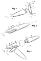
- Figure 1 : une vue éclatée d'un ensemble selon l'invention;
- Figure 2 : une vue assemblée d'un ensemble selon l'invention;
- Figure 3 : une vue en cours d'assemblage de l'ensemble selon la Figure 2;
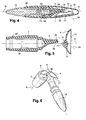
- Figure 4 : une vue en coupe d'une variante de réalisation d'un ensemble selon l'invention ;
- Figure 5 : une vue éclatée d'un organe de préhension muni de deux bras selon une variante de réalisation d'un ensemble selon l'invention ;
- Figure 6 : une vue en perspective d'une variante de réalisation d'un ensemble selon l'invention en cours de charge du moyen d'application;
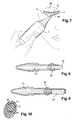
- Figure 7 : une vue en perspective d'une variante de réalisation d'un ensemble selon l'invention en cours d'application du moyen d'application sur une paupière;
- Figure 8 : une vue en coupe d'une première variante de réalisation d'un réservoir d'un ensemble selon l'invention;
- Figure 9 : une vue en coupe d'une deuxième variante de réalisation d'un réservoir d'un ensemble selon l'invention;
- Figure 10 : une vue en section transversale d'une jonction entre deux bras et un organe de préhension selon une variante de réalisation d'un ensemble selon l'invention.
- Figure 1: an exploded view of an assembly according to the invention;
- Figure 2: an assembled view of an assembly according to the invention;
- Figure 3: a view during assembly of the assembly according to Figure 2;
- Figure 4: a sectional view of an alternative embodiment of an assembly according to the invention;
- Figure 5: an exploded view of a gripping member provided with two arms according to an alternative embodiment of an assembly according to the invention;
- Figure 6: a perspective view of an alternative embodiment of an assembly according to the invention while charging the application means;
- Figure 7: a perspective view of an alternative embodiment of an assembly according to the invention during application of the application means on an eyelid;
- Figure 8: a sectional view of a first alternative embodiment of a reservoir of an assembly according to the invention;
- Figure 9: a sectional view of a second alternative embodiment of a reservoir of an assembly according to the invention;
- Figure 10: a cross-sectional view of a junction between two arms and a gripping member according to an alternative embodiment of an assembly according to the invention.
La Figure 1 montre un ensemble d'application 1 selon l'invention.
L'ensemble 1 comporte un organe de préhension 2, également appelé manche 2
dans la description qui va suivre, à une extrémité 3 de laquelle sont présentés
deux bras, de préférence flexibles, respectivement 4 et 5. Les bras 4 et 5 sont
assemblés l'un à l'autre au niveau d'une zone de préhension 6 reliée à l'extrémité
3 du manche 2. L'organe de préhension 2 comporte un axe d'allongement
principal 8. Les bras 4 et 5 supportent un moyen d'application 12.Figure 1 shows an application set 1 according to the invention.
The
Dans la variante présentée Figure 1, le manche 2 est détachable des bras
4 et 5. Le manche 2 comporte de facto un moyen de rétention 7 au niveau de son
extrémité 3 pour coopérer avec la zone de préhension 6. De préférence, ce moyen
de rétention 7 est élastique de manière à pouvoir se fixer et/ ou être détaché des
bras 4 et 5 de manière réversible. Réciproquement, l'extrémité 3 peut comporter
des moyens pour coopérer avec un moyen de rétention présenté par la zone 6.
Par exemple cette extrémité 3, définie sur l'organe de préhension 2 au niveau
d'une jonction avec cette zone de préhension 6 peut être élastiquement
déformable. L'extrémité 3 comporte alors par exemple un moyen formant ressort.In the variant shown in Figure 1, the
Par exemple, un intérêt de pouvoir détacher une unité formée des bras 4 et
5 et du moyen d'application 12 de l'organe de préhension 2 permet de changer le
moyen d'application 12, en particulier lorsqu'il est usé. L'unité usagée est alors par
exemple jetée. Une unité de remplacement comportant deux bras tels que 4 et 5
et un moyen d'application tel que 12 retenu entre ces deux bras peut alors être
montée sur l'organe de préhension 2 nu. De préférence, les unités peuvent être
différentes de manière à proposer des positions de bras différentes, ou des
moyens d'application de structures différentes. En effet, la structure du moyen
d'application 12 contribue à la forme du trait qui sera ensuite reproduit. Par
exemple, un coffret comportant de telles unités de remplacement peut présenter
des moyens d'application d'épaisseurs différentes, pour permettre de réaliser des
traits plus ou moins fins. En variante, ces unités de remplacement permettent
d'éviter d'endure le moyen d'application avec des produits différents, et
notamment de couleurs différentes.For example, an advantage of being able to detach a unit formed from the
Selon le mode de réalisation particulier représenté sur les figures 4 à 7 et
10, l'organe de préhension 2 comporte un pivot 30 engagé dans un logement
complémentaire 31 de la zone de préhension 6 des deux bras 4 et 5. Le pivot 30
est dressé orthogonalement selon un axe de pivot 34 relativement à une surface
32 de l'organe de préhension 2. Le logement complémentaire 31 débouche au
niveau d'une surface 33 de la zone de préhension 6. Les surfaces 32 et 33 sont
respectivement complémentaires de manière à pouvoir être accolées l'une à
l'autre lorsque le pivot 30 est engagé dans le logement 31, et de manière à tolérer
une rotation autour de ce pivot. Par exemple, les surfaces 32 et 33 sont planes.
En variante, les surfaces 32 et 33 sont respectivement en forme de dôme l'un
concave et l'autre convexe. Par exemple, ce dôme peut correspondre à une
hémisphère.According to the particular embodiment shown in Figures 4 to 7 and
10, the gripping
De préférence, les deux bras 4 et 5 sont fixes relativement à cette zone de
préhension 6 de manière à permettre une modification de l'orientation de ces deux
bras relativement à l'organe de préhension 2. En effet, les surfaces 32 et 33
forment un angle différent de 90° avec l'axe d'allongement principal 8. Ainsi en
fonction d'une rotation appliquée aux deux bras, leur position relativement à
l'organe de préhension 2 est modifiée. Les deux bras ne s'étendent pas
nécessairement dans un plan, mais ils sont configurés pour qu'un plan passant
par le moyen d'application 12 et la zone de préhension 6 puisse être sécante avec
l'axe d'allongement principal 8 dans au moins une position angulaire des deux
bras 4 et 5 relativement à l'organe de préhension 2.Preferably, the two
Figure 4, les deux bras 4 et 5 sont dans une première position disposés
dans un plan passant par l'axe d'allongement 8 et l'axe de pivot 34. De préférence
les surfaces 32 et 33 au niveau desquelles s'effectue la rotation sont légèrement
excentrées relativement à l'axe d'allongement principal 8. En particulier, l'axe
d'allongement principal 8 et l'axe de pivot 34 se coupent à distance des surfaces
32 et 33. De ce fait, notamment dans la mesure où les deux bras ne sont pas
symétriques l'un de l'autre, et en particulier dans le cas où le bras 5 est plus court
que le bras 4, alors cette première position correspond à une position
d'encombrement minimum, dans la mesure où seul le bras 5 le plus court dépasse
de l'organe de préhension 2 sensiblement le long de l'axe 8.Figure 4, the two
Figure 5, les deux bras ont subi une rotation de 180° relativement à la
position de la Figure 4 et sont dans une deuxième position tout en restant dans le
plan passant par l'axe d'allongement 8 et l'axe de pivot 34. Cette deuxième
position est différente de la première position dans le cas où les deux bras sont
différents l'un de l'autre. En particulier, dans cette deuxième position, le bras 4 le
plus long dépasse de l'organe de préhension 2. En l'occurrence, les bras sont
configurés de telle sorte que dans la première position, le moyen d'application 12
s'étend sensiblement parallèlement à l'axe d'allongement 8, alors que dans cette
deuxième position il s'étend sensiblement orthogonalement à cet axe
d'allongement 8.Figure 5, the two arms have been rotated 180 ° relative to the
position of Figure 4 and are in a second position while remaining in the
plane passing through the
Enfin dans une troisième position, Figure 6, les deux bras s'étendent
sensiblement dans un plan sécant au plan passant par l'axe d'allongement 8 et
l'axe de pivot 34. Dans cette troisième position, ces deux plans peuvent être
orthogonaux. Cette troisième position peut être obtenue par une rotation de 90°
relativement à l'une de la première ou de la deuxième positionFinally in a third position, Figure 6, the two arms extend
substantially in a plane intersecting the plane passing through the
De préférence, comme représenté à la figure 10, le pivot 30 comporte au
moins une rainure 50 apte à coopérer avec au moins trois gorges telles que 51
formées sur le pourtour intérieur du logement 31. La rainure 50 est
complémentaire des gorges telles que 51 pour indexer au moins les trois positions
mentionnées ci-dessus. Par exemple, le pivot 30 comporte deux rainures 50
diamétralement opposées pour coopérer avec quatre gorges 51, les gorges 51
étant équi-réparties sur le pourtour intérieur du logement 31. En variante, un relief
est prévu sur l'une des surfaces 32 ou 33 pour coopérer avec des creux
complémentaires prévus sur l'autre des surfaces 32 ou 33.Preferably, as shown in Figure 10, the
Dans une autre variante, non représentée, l'organe de préhension 2 est
moulé d'une pièce avec les bras 4 et 5. Dans ce cas, il est moulé dans un
matériau thermoplastique au moins légèrement flexible.In another variant, not shown, the gripping
Les bras 4 et 5 sont arqués. L'organe de préhension 2 est monté au niveau
d'un pourtour extérieur de cet arc. De préférence, selon l'exemple des Figures 1 à
3, les deux bras sont symétriques l'un de l'autre relativement à un axe coupant la
zone de préhension 6, et s'étendant selon l'axe d'allongement principal 8 du
manche 2. Dans l'exemple représenté aux Figures 1 à 3, les deux bras sont de
plus symétriques l'un de l'autre relativement à un plan passant par cet axe
d'allongement 8.
Globalement les bras 4 et 5 présentent une courbure 9, telle que l'axe 8 est
orthogonal à une tangente de cette courbure. Le premier bras 4 comporte une
première extrémité libre 10. Et le deuxième bras 5 comporte une deuxième
extrémité libre 11. En particulier, ils forment un arc de cercle, et les extrémités 10
et 11 peuvent être diamétralement opposées.Overall the
Le moyen d'application 12 est retenu entre ces deux extrémités 10 et 11.
Ce moyen d'application 12 est de préférence allongé et forme une bande souple
par exemple retenue respectivement par deux articulations 13 et 14 sur chacune
des extrémités 10 et 11. Ces articulations 13 et 14 peuvent par exemple pivoter
selon des axes respectivement orthogonaux à l'axe d'allongement 8.The application means 12 is retained between these two ends 10 and 11.
This application means 12 is preferably elongated and forms a flexible strip
for example retained respectively by two
De préférence, à proximité d'au moins une des extrémités de ce moyen
d'application 12, le moyen d'application 12 comporte un bossage constituant un
élément excroissant, sensible lors de son application, et donc formant un élément
tactile aidant au positionnement d'un premier point du moyen d'application 12
relativement à la surface à enduire.Preferably, near at least one of the ends of this means
Dans une variante, le moyen d'application 12 est tendu entre les deux extrémités 10 et 11, non munies d'articulations, mais présentant seulement des moyens pour retenir chacune une terminaison du moyen d'application 12. Par exemple, les extrémités 10 et 11 sont munies de fentes dans lesquelles la bande formée par le moyen d'application 12 peut être retenue.Alternatively, the application means 12 is stretched between the two ends 10 and 11, not provided with articulations, but having only means for each retaining a termination of the application means 12. By example, the ends 10 and 11 are provided with slots in which the strip formed by the application means 12 can be retained.
Schématiquement, l'ensemble 1 ressemble à une arme pour tirer des
flèches, les bras flexibles correspondant à un arc et le moyen d'application
correspondant à la corde de cet arc.Schematically, the
Le moyen d'application 12 peut être élastiquement déformable. Dans ce cas également, il n'est pas absolument nécessaire de prévoir des articulations à pivot telles que 13 et 14. La longueur de ce moyen d'application 12 est alors modulable de manière à s'adapter à la longueur du trait désiré.The application means 12 can be elastically deformable. In this also, it is not absolutely necessary to provide joints to pivot such as 13 and 14. The length of this application means 12 is then modular so as to adapt to the length of the desired line.
En variante, les bras 4 et 5 peuvent aussi être élastiquement déformables.As a variant, the
Pour réaliser un trait à partir du dispositif 1, l'utilisatrice saisit l'organe de
préhension 2 dans une de ses mains, elle dispose l'une des extrémités 10 ou 11 à
proximité d'un point à partir duquel elle veut réaliser son trait. Ensuite, elle pivote
le dispositif autour de cette première extrémité appuyée contre la surface à
enduire, formant un pivot. Le moyen d'application 12 est ainsi progressivement
mis en contact avec la surface à enduire. Etant donné la forme allongée de ce
moyen d'application 12, on obtient un trait d'épaisseur quasiment constante. De
plus, étant donné la souplesse de ce moyen d'application 12, et la flexibilité
conférée par les bras flexibles 4 et 5 et éventuellement par les articulations 13 et
14, l'ensemble 1 peut venir au contact d'une surface courbe à enduire.
Notamment, il est adapté pour s'adapter à la morphologie d'une paupière
généralement convexe.To make a line from
De préférence, la première extrémité 10, ou respectivement 11, est
disposée au niveau d'une commissure intérieure de la paupière, et la main est
déplacée en direction de la paupière de manière à positionner la deuxième
extrémité 11, ou respectivement 10, au niveau d'une commissure externe de cette
paupière. Inversement, et notamment dans le cas où on ne voudrait pas recouvrir
toute la bordure de la paupière avec un tel trait, on dispose premièrement une des
extrémités au niveau de la commissure externe de l'oeil et on tourne la main de
manière à former progressivement ce trait en s'arrêtant avant d'atteindre la
commissure interne de l'oeil.Preferably, the
Le moyen d'application 12 est de préférence au préalable enduit du produit
à appliquer au moyen d'un tampon encreur 35. Ce tampon encreur 35 est par
exemple disposé en communication avec un réservoir 15. Le tampon encreur 35
est par exemple, figures 2 et 3, en forme de U tel que le creux du U est présenté
en regard d'une fente 16 du réservoir 15. Le tampon encreur 35 est par exemple
obtenu à partir d'une mousse à cellule ouverte imprégnée du produit contenu dans
le réservoir 15 par capillarité. En variante, le réservoir 15 est muni d'un stick ou
d'un piston ou encore de parois déformables de manière à pouvoir comprimer le
produit en direction du tampon encreur 35.The application means 12 is preferably coated beforehand with the product.
to be applied by means of an
Figures 2 et 3, le moyen d'application 12 peut être inséré dans cette fente
16. En particulier, le réservoir 15 est prévu pour pouvoir retenir ce moyen
d'application 12. Dans le cas où l'organe de préhension 2 est démontable, seul le
moyen d'application 12 et une portion des bras flexibles 4 et 5 sont insérés dans la
fente 16. Le réservoir peut par ailleurs comporter d'autres moyens de rétention 17
pour retenir l'organe de préhension 2 sur le réservoir. Le réservoir 15 a par
exemple une forme allongée, la fente 16 étant formée le long d'un axe
d'allongement principal 18 du réservoir 15. Dans cet exemple, l'organe de
préhension 2 est monté sur le réservoir 15, de telle sorte que son axe
d'allongement principal 8 se superpose avec l'axe 18.Figures 2 and 3, the application means 12 can be inserted into this
Notamment, l'extrémité 3 du manche 2 présente des moyens
complémentaires 19 pour coopérer avec les moyens de rétention 17 du réservoir
15. Le réservoir 15 comporte alors un logement dont une ouverture 22 est définie
orthogonalement à l'axe 18, et tel que les moyens de rétention 7 de l'extrémité 3
peuvent y être insérés. En particulier, ce logement présente sur une paroi
intérieure une rainure pour coopérer avec un pourtour fileté présenté par les
moyens complémentaires 19.In particular, the
Par exemple, pour retenir le moyen d'application 12 dans la fente 16, cette
fente 16 a une longueur, relativement à l'axe 18, qui est inférieure à la distance
entre les deux extrémités 10 et 11 des deux bras flexibles, soit inférieure à une
longueur au repos du moyen d'application 12.For example, to retain the application means 12 in the
Pour pouvoir insérer ce moyen d'application 12 dans la fente 16, il est donc
nécessaire de contraindre les bras 4 et 5 ici flexibles de manière à en rapprocher
leurs extrémités 10 et 11. A cet effet, on présente de préférence une extrémité 10
ou 11 en butée contre un coin 20 de la fente 16, et ensuite on effectue une
rotation autour de ce coin 20 formant pivot tout en contraignant le bras flexible non
engagé dans la fente 16 en direction de l'autre bras. Lorsque l'autre extrémité 11
ou 10 est descendue vers la fente 16, celle ci peut être introduite sans difficultés.
Une fois que le moyen d'application 12 est totalement inséré dans la fente 16, la
contrainte exercée sur le coin 20 est relâchée. Cette autre extrémité 11 ou 10
vient alors en butée contre un deuxième coin 21 opposé au coin 20. La distance
entre ces coins 20 et 21 est telle que le moyen d'application 12 ne peut plus
ressortir à moins d'exercer à nouveau une contrainte en direction de l'un des coins
20 ou 21, et d'entraíner ensuite en rotation le moyen d'application autour d'un pivot
formé par ce coin.To be able to insert this application means 12 into the
Une fois que le moyen d'application 12 est retenu dans la fente 16, on peut
détacher l'organe de préhension 2 de la zone de préhension 6 qui reste de
préférence extérieure à la fente 16. L'organe de préhension 2 est alors monté sur
le réservoir 15 comme indiqué ci-dessus.Once the application means 12 is retained in the
En variante, Figures 4 et 6, le tampon encreur 35 est disposé au niveau
d'un col 36 du réservoir 15. Le tampon encreur 35 obture alors le col de manière à
être en communication fluidique permanente avec l'intérieur du réservoir 15 et du
produit qui y est contenu. Le tampon 35 est en permanence imbibé de produit. La
largeur du col 36 est ici nettement inférieur à la longueur du moyen d'application
12 à enduire. De préférence, le col 36 comporte deux fentes telles que 37
diamétralement opposées de manière à permettre de faire coulisser le moyen
d'application 12 entre ces deux fentes. Toute la longueur du moyen d'application
12 peut être coulissée entre ces deux fentes telles que 37. De préférence, le
tampon encreur 35 est disposé de manière à être comprimé contre le moyen
d'application 12 lorsque celui ci est enfoncé totalement dans le creux des fentes
telles que 37.Alternatively, Figures 4 and 6, the
En variante, Figure 8, le tampon encreur 35 dépasse à l'extérieur du col 36,
le tampon 35 étant en communication fluidique avec l'intérieur de réservoir 15 et
avec le produit qui y est contenu. Le tampon 35 comporte alors une gorge
annulaire pour coopérer avec une lèvre annulaire radialement proéminente d'un
pourtour intérieur du col 36 pour y être retenu. Le tampon 35 peut dans ce cas
également être légèrement écrasé, voir légèrement enfoncé dans le col 36, lors de
l'application contre le moyen d'application 12.As a variant, in FIG. 8, the
Selon une autre variante, figure 9, pour éviter de devoir déplacer le tampon
35 sur toute la longueur du moyen d'application 12, le tampon présente une
longueur sensiblement identique à celle du moyen d'application 12. Par ailleurs,
pour éviter d'avoir à déplacer le moyen d'application 12 dans une fente telle que
16 ou 37, le col 36 n'étant pas nécessairement élargi pour ce besoin, le tampon 35
est alors de préférence présenté sur le pourtour latéral extérieur du col 36. Le col
36 comporte alors une fenêtre latérale de laquelle dépasse le tampon 35, cette
fenêtre débouchant dans une cavité de section trapézoïdale configurée pour y
retenir le tampon 35. Le tampon 35 y est alors monté en force. Dans cette variante
également, le tampon 35 reste en communication fluidique avec l'intérieur du
réservoir 15. La longueur de ce pourtour latéral extérieur le long de l'axe
d'allongement 18 du réservoir 15 est sensiblement égal à la longueur du moyen
d'application 12.According to another variant, FIG. 9, to avoid having to move the
Dans les exemples présentés Figures 4 à 9, ce réservoir 15 est prévu pour
être fixé dans une cavité 38 de l'organe de préhension 2. De préférence, le col 36
muni de son tampon encreur 35 est disposé dans cette cavité 38. L'organe de
préhension 2 sert alors de capsule de fermeture du réservoir 15. Le réservoir 15
est inséré au niveau d'une zone arrière de l'organe de préhension 2, opposée à
l'extrémité 3 au niveau de laquelle les bras 4 et 5 sont rattachés. Par exemple, le
réservoir 15 présente sur son pourtour extérieur des moyens de rétention 39 apte
à coopérer avec des moyens complémentaires 40 présentés sur le pourtour
intérieur de la cavité 38. Par exemple, le moyen de rétention 39 est une collerette
annulaire apte à venir s'encliqueter dans une gorge annulaire 40 du pourtour
intérieur de cette cavité 38.In the examples presented in FIGS. 4 to 9, this
De préférence, le pourtour extérieur du col 36 comporte également un jonc
annulaire 41 apte à venir en butée sur le pourtour intérieur de la cavité 38, de
manière à assurer une jonction étanche. Dans ce cas, le réservoir 15 est monté
étanche à l'intérieur de la cavité 38.Preferably, the outer periphery of the
Une utilisation préférée d'un tel ensemble 1 consiste à retirer un capuchon
42 monté sur l'organe de préhension 2, le capuchon 42 servant à masquer les
deux bras 4 et 5 et le moyen d'application 12, notamment lorsqu'ils sont dans la
première position. Le capuchon 42 peut également servir à maintenir le moyen
d'application 12 dans un environnement d'humidité constante. Par exemple, le
capuchon 42 comporte un humidificateur permettant de prévenir le dessèchement
du moyen applicateur 12. A preferred use of such a
Ensuite, l'utilisatrice dégage le réservoir 15 de la cavité 38, pour venir
ensuite enduire le moyen d'application 12 au moyen du tampon encreur 35, voir
Figure 6. Enfin l'utilisatrice applique ce moyen d'application 12 enduit de produit
sur une paupière 43, voir Figure 7, notamment à proximité de la base des cils 44.Then, the user releases the
De préférence, avant l'application du moyen d'application 12 sur la
paupière, l'utilisatrice range à nouveau le réservoir 15 dans l'organe de préhension
2, l'organe de préhension 2 étant ainsi lesté par le réservoir 15, il est donc plus
agréable à manipuler.Preferably, before the application means 12 are applied to the
eyelid, the user again stores the
En variante, non représenté, un capuchon tel que 42 comporte un
deuxième réservoir formant une réserve de produit, par exemple d'un produit
différent de celui contenu dans le réservoir 15. Ce deuxième réservoir est par
exemple présenté au niveau du pourtour intérieur du capuchon 42, et dans ce cas,
dans une position fermée de l'ensemble, le moyen d'application 12 est maintenu
au contact de cette réserve de produit. Alternativement, ce deuxième réservoir
peut être accessible uniquement depuis le pourtour extérieur de ce capuchon 42.
Et dans ce cas, le capuchon doit être préalablement dégagé de l'organe de
préhension 2 pour permettre d'enduire le moyen d'application 12 avec le produit
de ce deuxième réservoir.Alternatively, not shown, a cap such as 42 includes a
second reservoir forming a reserve of product, for example of a product
different from that contained in the
Dans toute la description, y compris les revendications, l'expression « comportant un » doit être comprise comme étant synonyme de « comportant au moins un », sauf si le contraire est spécifié.Throughout the description, including the claims, the expression "Comprising a" should be understood as being synonymous with "comprising minus one ”, unless otherwise specified.
Claims (29)
Applications Claiming Priority (2)
| Application Number | Priority Date | Filing Date | Title |
|---|---|---|---|
| FR0304572 | 2003-04-11 | ||
| FR0304572A FR2853506B1 (en) | 2003-04-11 | 2003-04-11 | DEVICE FOR APPLYING A TRAITE |
Publications (3)
| Publication Number | Publication Date |
|---|---|
| EP1466542A2 true EP1466542A2 (en) | 2004-10-13 |
| EP1466542A3 EP1466542A3 (en) | 2004-12-29 |
| EP1466542B1 EP1466542B1 (en) | 2007-05-09 |
Family
ID=32865420
Family Applications (1)
| Application Number | Title | Priority Date | Filing Date |
|---|---|---|---|
| EP04290975A Expired - Lifetime EP1466542B1 (en) | 2003-04-11 | 2004-04-13 | Device for the application of a line |
Country Status (5)
| Country | Link |
|---|---|
| EP (1) | EP1466542B1 (en) |
| AT (1) | ATE361684T1 (en) |
| DE (1) | DE602004006335T2 (en) |
| ES (1) | ES2287665T3 (en) |
| FR (1) | FR2853506B1 (en) |
Cited By (1)
| Publication number | Priority date | Publication date | Assignee | Title |
|---|---|---|---|---|
| WO2015189527A1 (en) * | 2014-06-13 | 2015-12-17 | Bourjois | Cosmetic product article comprising a stamp |
Citations (7)
| Publication number | Priority date | Publication date | Assignee | Title |
|---|---|---|---|---|
| GB317816A (en) * | 1928-05-23 | 1929-08-23 | William Arthur Hearsey | Means for improving the appearance of the face and features |
| US2136779A (en) * | 1937-11-04 | 1938-11-15 | Henry J Bednar | Eyelash darkener |
| FR947341A (en) * | 1947-05-28 | 1949-06-29 | Devices for automatically cosmetic eyelashes | |
| FR2065297A5 (en) * | 1969-10-10 | 1971-07-23 | Fairbanks Wayne Kent | |
| US4483356A (en) * | 1982-08-11 | 1984-11-20 | Kales Donna R | Hand-held lotion applicator |
| US5927295A (en) * | 1997-09-30 | 1999-07-27 | Quinones; Lydia E. | Eyelash comb |
| US6508255B1 (en) * | 2000-10-25 | 2003-01-21 | Color Access, Inc. | Eyeliner applicator |
-
2003
- 2003-04-11 FR FR0304572A patent/FR2853506B1/en not_active Expired - Fee Related
-
2004
- 2004-04-13 DE DE602004006335T patent/DE602004006335T2/en not_active Expired - Lifetime
- 2004-04-13 AT AT04290975T patent/ATE361684T1/en not_active IP Right Cessation
- 2004-04-13 EP EP04290975A patent/EP1466542B1/en not_active Expired - Lifetime
- 2004-04-13 ES ES04290975T patent/ES2287665T3/en not_active Expired - Lifetime
Patent Citations (7)
| Publication number | Priority date | Publication date | Assignee | Title |
|---|---|---|---|---|
| GB317816A (en) * | 1928-05-23 | 1929-08-23 | William Arthur Hearsey | Means for improving the appearance of the face and features |
| US2136779A (en) * | 1937-11-04 | 1938-11-15 | Henry J Bednar | Eyelash darkener |
| FR947341A (en) * | 1947-05-28 | 1949-06-29 | Devices for automatically cosmetic eyelashes | |
| FR2065297A5 (en) * | 1969-10-10 | 1971-07-23 | Fairbanks Wayne Kent | |
| US4483356A (en) * | 1982-08-11 | 1984-11-20 | Kales Donna R | Hand-held lotion applicator |
| US5927295A (en) * | 1997-09-30 | 1999-07-27 | Quinones; Lydia E. | Eyelash comb |
| US6508255B1 (en) * | 2000-10-25 | 2003-01-21 | Color Access, Inc. | Eyeliner applicator |
Cited By (2)
| Publication number | Priority date | Publication date | Assignee | Title |
|---|---|---|---|---|
| WO2015189527A1 (en) * | 2014-06-13 | 2015-12-17 | Bourjois | Cosmetic product article comprising a stamp |
| FR3022124A1 (en) * | 2014-06-13 | 2015-12-18 | Bourjois | COSMETIC PRODUCT ARTICLE WITH CONTACT AREA |
Also Published As
| Publication number | Publication date |
|---|---|
| ES2287665T3 (en) | 2007-12-16 |
| EP1466542A3 (en) | 2004-12-29 |
| FR2853506B1 (en) | 2006-12-08 |
| FR2853506A1 (en) | 2004-10-15 |
| EP1466542B1 (en) | 2007-05-09 |
| ATE361684T1 (en) | 2007-06-15 |
| DE602004006335T2 (en) | 2008-01-10 |
| DE602004006335D1 (en) | 2007-06-21 |
Similar Documents
| Publication | Publication Date | Title |
|---|---|---|
| EP1452111B1 (en) | Device for storage and application of a cosmetic | |
| EP3420845B1 (en) | Cosmetic-product applicator tip, associated applicator and applicator unit | |
| EP0916282B1 (en) | Device for storing and applying,including a container,an ergonomic applicator and a wiper | |
| CA2406362C (en) | Product applicator device, namely a cosmetic product applicator with a removable applicator unit | |
| EP1477083B2 (en) | Applicator and container comprising such an applicator | |
| EP0474319A2 (en) | Applicator unit for eyelash make-up comprising a mascara cake and a humified dispensing element | |
| EP0960584B1 (en) | Device for storing and applying a composition to keratin fibers | |
| EP1053695A2 (en) | Device for storing and applying cosmetic products, especially for lipsticks | |
| EP1336353A1 (en) | Applicator comprising an applicator element configured to apply a product to the skin | |
| FR2753056A1 (en) | MAKEUP OR CARE PRODUCT APPLICATOR | |
| EP1634616A1 (en) | Application unit with amovible applicator | |
| FR3095116A1 (en) | COSMETIC APPLICATOR WITH FLEXIBLE AND RIGID PORTIONS | |
| EP1228715B1 (en) | Applicator unit, in particular for a make-up product | |
| EP1440629B1 (en) | Applicator for applying a substance on a part of the human body | |
| FR3036598A1 (en) | APPLICATION AND MASSAGE DEVICE | |
| US20040258454A1 (en) | Device for application of a line | |
| FR3027778A1 (en) | APPLICATOR FOR APPLYING A COSMETIC OR CARE PRODUCT | |
| EP0610107A1 (en) | Mascara applicator and mascara storage and application unit | |
| FR3025986A1 (en) | COSMETIC OR CARE PRODUCT APPLICATOR | |
| EP1369055B1 (en) | Applicator with a stem joined to a gripping member by an articulation | |
| EP0960582A1 (en) | Case for a spreadable composition comprising an applicator | |
| EP1466542B1 (en) | Device for the application of a line | |
| EP1428455B2 (en) | Applicator, in particular for cosmetics | |
| EP1393649B1 (en) | Product packaging and application device, especially for an eyeliner | |
| FR2836029A1 (en) | Nail varnish applicator has surface which is shaped to produce curved mark in clear varnish at tip of nail |
Legal Events
| Date | Code | Title | Description |
|---|---|---|---|
| PUAI | Public reference made under article 153(3) epc to a published international application that has entered the european phase |
Free format text: ORIGINAL CODE: 0009012 |
|
| AK | Designated contracting states |
Kind code of ref document: A2 Designated state(s): AT BE BG CH CY CZ DE DK EE ES FI FR GB GR HU IE IT LI LU MC NL PL PT RO SE SI SK TR |
|
| AX | Request for extension of the european patent |
Extension state: AL HR LT LV MK |
|
| PUAL | Search report despatched |
Free format text: ORIGINAL CODE: 0009013 |
|
| AK | Designated contracting states |
Kind code of ref document: A3 Designated state(s): AT BE BG CH CY CZ DE DK EE ES FI FR GB GR HU IE IT LI LU MC NL PL PT RO SE SI SK TR |
|
| AX | Request for extension of the european patent |
Extension state: AL HR LT LV MK |
|
| 17P | Request for examination filed |
Effective date: 20050629 |
|
| AKX | Designation fees paid |
Designated state(s): AT BE BG CH CY CZ DE DK EE ES FI FR GB GR HU IE IT LI LU MC NL PL PT RO SE SI SK TR |
|
| GRAP | Despatch of communication of intention to grant a patent |
Free format text: ORIGINAL CODE: EPIDOSNIGR1 |
|
| GRAS | Grant fee paid |
Free format text: ORIGINAL CODE: EPIDOSNIGR3 |
|
| GRAA | (expected) grant |
Free format text: ORIGINAL CODE: 0009210 |
|
| AK | Designated contracting states |
Kind code of ref document: B1 Designated state(s): AT BE BG CH CY CZ DE DK EE ES FI FR GB GR HU IE IT LI LU MC NL PL PT RO SE SI SK TR |
|
| PG25 | Lapsed in a contracting state [announced via postgrant information from national office to epo] |
Ref country code: FI Free format text: LAPSE BECAUSE OF FAILURE TO SUBMIT A TRANSLATION OF THE DESCRIPTION OR TO PAY THE FEE WITHIN THE PRESCRIBED TIME-LIMIT Effective date: 20070509 |
|
| REG | Reference to a national code |
Ref country code: GB Ref legal event code: FG4D Free format text: NOT ENGLISH |
|
| REG | Reference to a national code |
Ref country code: CH Ref legal event code: EP |
|
| REG | Reference to a national code |
Ref country code: IE Ref legal event code: FG4D Free format text: LANGUAGE OF EP DOCUMENT: FRENCH |
|
| REF | Corresponds to: |
Ref document number: 602004006335 Country of ref document: DE Date of ref document: 20070621 Kind code of ref document: P |
|
| GBT | Gb: translation of ep patent filed (gb section 77(6)(a)/1977) |
Effective date: 20070712 |
|
| PG25 | Lapsed in a contracting state [announced via postgrant information from national office to epo] |
Ref country code: SE Free format text: LAPSE BECAUSE OF FAILURE TO SUBMIT A TRANSLATION OF THE DESCRIPTION OR TO PAY THE FEE WITHIN THE PRESCRIBED TIME-LIMIT Effective date: 20070809 |
|
| NLV1 | Nl: lapsed or annulled due to failure to fulfill the requirements of art. 29p and 29m of the patents act | ||
| PG25 | Lapsed in a contracting state [announced via postgrant information from national office to epo] |
Ref country code: PL Free format text: LAPSE BECAUSE OF FAILURE TO SUBMIT A TRANSLATION OF THE DESCRIPTION OR TO PAY THE FEE WITHIN THE PRESCRIBED TIME-LIMIT Effective date: 20070509 Ref country code: AT Free format text: LAPSE BECAUSE OF FAILURE TO SUBMIT A TRANSLATION OF THE DESCRIPTION OR TO PAY THE FEE WITHIN THE PRESCRIBED TIME-LIMIT Effective date: 20070509 |
|
| REG | Reference to a national code |
Ref country code: ES Ref legal event code: FG2A Ref document number: 2287665 Country of ref document: ES Kind code of ref document: T3 |
|
| REG | Reference to a national code |
Ref country code: IE Ref legal event code: FD4D |
|
| PG25 | Lapsed in a contracting state [announced via postgrant information from national office to epo] |
Ref country code: SI Free format text: LAPSE BECAUSE OF FAILURE TO SUBMIT A TRANSLATION OF THE DESCRIPTION OR TO PAY THE FEE WITHIN THE PRESCRIBED TIME-LIMIT Effective date: 20070509 Ref country code: PT Free format text: LAPSE BECAUSE OF FAILURE TO SUBMIT A TRANSLATION OF THE DESCRIPTION OR TO PAY THE FEE WITHIN THE PRESCRIBED TIME-LIMIT Effective date: 20071009 Ref country code: DK Free format text: LAPSE BECAUSE OF FAILURE TO SUBMIT A TRANSLATION OF THE DESCRIPTION OR TO PAY THE FEE WITHIN THE PRESCRIBED TIME-LIMIT Effective date: 20070509 Ref country code: NL Free format text: LAPSE BECAUSE OF FAILURE TO SUBMIT A TRANSLATION OF THE DESCRIPTION OR TO PAY THE FEE WITHIN THE PRESCRIBED TIME-LIMIT Effective date: 20070509 Ref country code: BG Free format text: LAPSE BECAUSE OF FAILURE TO SUBMIT A TRANSLATION OF THE DESCRIPTION OR TO PAY THE FEE WITHIN THE PRESCRIBED TIME-LIMIT Effective date: 20070809 Ref country code: IE Free format text: LAPSE BECAUSE OF FAILURE TO SUBMIT A TRANSLATION OF THE DESCRIPTION OR TO PAY THE FEE WITHIN THE PRESCRIBED TIME-LIMIT Effective date: 20070509 Ref country code: CZ Free format text: LAPSE BECAUSE OF FAILURE TO SUBMIT A TRANSLATION OF THE DESCRIPTION OR TO PAY THE FEE WITHIN THE PRESCRIBED TIME-LIMIT Effective date: 20070509 |
|
| PG25 | Lapsed in a contracting state [announced via postgrant information from national office to epo] |
Ref country code: SK Free format text: LAPSE BECAUSE OF FAILURE TO SUBMIT A TRANSLATION OF THE DESCRIPTION OR TO PAY THE FEE WITHIN THE PRESCRIBED TIME-LIMIT Effective date: 20070509 |
|
| PLBE | No opposition filed within time limit |
Free format text: ORIGINAL CODE: 0009261 |
|
| STAA | Information on the status of an ep patent application or granted ep patent |
Free format text: STATUS: NO OPPOSITION FILED WITHIN TIME LIMIT |
|
| 26N | No opposition filed |
Effective date: 20080212 |
|
| PG25 | Lapsed in a contracting state [announced via postgrant information from national office to epo] |
Ref country code: GR Free format text: LAPSE BECAUSE OF FAILURE TO SUBMIT A TRANSLATION OF THE DESCRIPTION OR TO PAY THE FEE WITHIN THE PRESCRIBED TIME-LIMIT Effective date: 20070810 |
|
| PG25 | Lapsed in a contracting state [announced via postgrant information from national office to epo] |
Ref country code: RO Free format text: LAPSE BECAUSE OF FAILURE TO SUBMIT A TRANSLATION OF THE DESCRIPTION OR TO PAY THE FEE WITHIN THE PRESCRIBED TIME-LIMIT Effective date: 20070509 |
|
| BERE | Be: lapsed |
Owner name: L'OREAL Effective date: 20080430 |
|
| PG25 | Lapsed in a contracting state [announced via postgrant information from national office to epo] |
Ref country code: MC Free format text: LAPSE BECAUSE OF NON-PAYMENT OF DUE FEES Effective date: 20080430 |
|
| REG | Reference to a national code |
Ref country code: CH Ref legal event code: PL |
|
| PG25 | Lapsed in a contracting state [announced via postgrant information from national office to epo] |
Ref country code: EE Free format text: LAPSE BECAUSE OF FAILURE TO SUBMIT A TRANSLATION OF THE DESCRIPTION OR TO PAY THE FEE WITHIN THE PRESCRIBED TIME-LIMIT Effective date: 20070509 Ref country code: CH Free format text: LAPSE BECAUSE OF NON-PAYMENT OF DUE FEES Effective date: 20080430 Ref country code: LI Free format text: LAPSE BECAUSE OF NON-PAYMENT OF DUE FEES Effective date: 20080430 |
|
| PG25 | Lapsed in a contracting state [announced via postgrant information from national office to epo] |
Ref country code: BE Free format text: LAPSE BECAUSE OF NON-PAYMENT OF DUE FEES Effective date: 20080430 |
|
| PG25 | Lapsed in a contracting state [announced via postgrant information from national office to epo] |
Ref country code: CY Free format text: LAPSE BECAUSE OF FAILURE TO SUBMIT A TRANSLATION OF THE DESCRIPTION OR TO PAY THE FEE WITHIN THE PRESCRIBED TIME-LIMIT Effective date: 20070509 |
|
| PGFP | Annual fee paid to national office [announced via postgrant information from national office to epo] |
Ref country code: GB Payment date: 20100325 Year of fee payment: 7 |
|
| PG25 | Lapsed in a contracting state [announced via postgrant information from national office to epo] |
Ref country code: LU Free format text: LAPSE BECAUSE OF NON-PAYMENT OF DUE FEES Effective date: 20080413 Ref country code: HU Free format text: LAPSE BECAUSE OF FAILURE TO SUBMIT A TRANSLATION OF THE DESCRIPTION OR TO PAY THE FEE WITHIN THE PRESCRIBED TIME-LIMIT Effective date: 20071110 |
|
| PGFP | Annual fee paid to national office [announced via postgrant information from national office to epo] |
Ref country code: ES Payment date: 20100505 Year of fee payment: 7 Ref country code: FR Payment date: 20100521 Year of fee payment: 7 |
|
| PG25 | Lapsed in a contracting state [announced via postgrant information from national office to epo] |
Ref country code: TR Free format text: LAPSE BECAUSE OF FAILURE TO SUBMIT A TRANSLATION OF THE DESCRIPTION OR TO PAY THE FEE WITHIN THE PRESCRIBED TIME-LIMIT Effective date: 20070509 |
|
| PGFP | Annual fee paid to national office [announced via postgrant information from national office to epo] |
Ref country code: DE Payment date: 20100430 Year of fee payment: 7 Ref country code: IT Payment date: 20100417 Year of fee payment: 7 |
|
| GBPC | Gb: european patent ceased through non-payment of renewal fee |
Effective date: 20110413 |
|
| REG | Reference to a national code |
Ref country code: FR Ref legal event code: ST Effective date: 20111230 |
|
| PG25 | Lapsed in a contracting state [announced via postgrant information from national office to epo] |
Ref country code: DE Free format text: LAPSE BECAUSE OF NON-PAYMENT OF DUE FEES Effective date: 20111101 Ref country code: FR Free format text: LAPSE BECAUSE OF NON-PAYMENT OF DUE FEES Effective date: 20110502 |
|
| REG | Reference to a national code |
Ref country code: DE Ref legal event code: R119 Ref document number: 602004006335 Country of ref document: DE Effective date: 20111101 |
|
| PG25 | Lapsed in a contracting state [announced via postgrant information from national office to epo] |
Ref country code: GB Free format text: LAPSE BECAUSE OF NON-PAYMENT OF DUE FEES Effective date: 20110413 Ref country code: IT Free format text: LAPSE BECAUSE OF NON-PAYMENT OF DUE FEES Effective date: 20110413 |
|
| REG | Reference to a national code |
Ref country code: ES Ref legal event code: FD2A Effective date: 20120604 |
|
| PG25 | Lapsed in a contracting state [announced via postgrant information from national office to epo] |
Ref country code: ES Free format text: LAPSE BECAUSE OF NON-PAYMENT OF DUE FEES Effective date: 20110414 |