EP1466542A2 - Auftragsvorrichtung für einen Strich - Google Patents
Auftragsvorrichtung für einen Strich Download PDFInfo
- Publication number
- EP1466542A2 EP1466542A2 EP04290975A EP04290975A EP1466542A2 EP 1466542 A2 EP1466542 A2 EP 1466542A2 EP 04290975 A EP04290975 A EP 04290975A EP 04290975 A EP04290975 A EP 04290975A EP 1466542 A2 EP1466542 A2 EP 1466542A2
- Authority
- EP
- European Patent Office
- Prior art keywords
- arms
- gripping member
- assembly according
- application
- reservoir
- Prior art date
- Legal status (The legal status is an assumption and is not a legal conclusion. Google has not performed a legal analysis and makes no representation as to the accuracy of the status listed.)
- Granted
Links
Images
Classifications
-
- B—PERFORMING OPERATIONS; TRANSPORTING
- B43—WRITING OR DRAWING IMPLEMENTS; BUREAU ACCESSORIES
- B43L—ARTICLES FOR WRITING OR DRAWING UPON; WRITING OR DRAWING AIDS; ACCESSORIES FOR WRITING OR DRAWING
- B43L25/00—Ink receptacles
- B43L25/007—Portable ink receptacles; Filling devices for receptacles
-
- A—HUMAN NECESSITIES
- A45—HAND OR TRAVELLING ARTICLES
- A45D—HAIRDRESSING OR SHAVING EQUIPMENT; EQUIPMENT FOR COSMETICS OR COSMETIC TREATMENTS, e.g. FOR MANICURING OR PEDICURING
- A45D40/00—Casings or accessories specially adapted for storing or handling solid or pasty toiletry or cosmetic substances, e.g. shaving soaps or lipsticks
- A45D40/26—Appliances specially adapted for applying pasty paint, e.g. using roller, using a ball
-
- B—PERFORMING OPERATIONS; TRANSPORTING
- B43—WRITING OR DRAWING IMPLEMENTS; BUREAU ACCESSORIES
- B43L—ARTICLES FOR WRITING OR DRAWING UPON; WRITING OR DRAWING AIDS; ACCESSORIES FOR WRITING OR DRAWING
- B43L25/00—Ink receptacles
- B43L25/10—Ink receptacles with means for holding objects
-
- A—HUMAN NECESSITIES
- A45—HAND OR TRAVELLING ARTICLES
- A45D—HAIRDRESSING OR SHAVING EQUIPMENT; EQUIPMENT FOR COSMETICS OR COSMETIC TREATMENTS, e.g. FOR MANICURING OR PEDICURING
- A45D2200/00—Details not otherwise provided for in A45D
- A45D2200/10—Details of applicators
- A45D2200/1072—Eyeliners
Definitions
- the subject of the present invention is a device for applying a stroke, especially to make a line from a cosmetic product on a surface to coated.
- the invention is in particular of interest in the field of applicators cosmetics such as liners, also called “eyeliners”, intended for the realization of a continuous or discontinuous line at the edge of the eyelids.
- the line applied is intended to emphasize the eye contour, to modify their line and their dimension.
- Application devices allow fine application and precise with such a continuous line, the application being able to be carried out with one hand and in particular by not requiring the use of a mirror to control the application.
- the gestures associated with the device of the invention allows to coat the contour of an eyelid, with certainty, over a defined length and controlling the starting point of the line.
- the application can be carried out in conditions where the user is shaken, for example in a means of transport, because this application can be done by keeping permanently a fixed fulcrum on the eyelid.
- eyeliners such as the applicator, in the shape of a point, is mounted at the end of a rod fixed in a cover, and this cover is intended to be mounted on a product tank so that the applicator is immersed in the product in an assembled position of the cover on the tank. Then, the user who wants to draw a line around the border of her eyelid should regularly move the tip of the applicator along the surface to coat. This makeup operation is difficult to carry out without erasures. The trait obtained often involves unwanted dropouts.
- applicators cosmetics for depositing false eyelashes at the edge of an eyelid Such applicator has two arms arranged like scissors such as a support is disposed between the ends of the two arms. This support is sticky and suitable for retain these false eyelashes. Depending on the spacing of the two arms, the support adopts a more or less concave shape to adapt to the more or less shape convex eyelid of the user. Handling such an applicator requires the ability to keep both arms at a specific distance to maintain the curvature of the support. This type of applicator poses a problem because that he forces the user to contract his hands and to maintain this contraction during the application of false eyelashes. In addition, if the applicator is kept in a convex shape, the false eyelash is then more difficult to detach from its adhesive backing.
- the invention proposes for this purpose to have an application means, preferably flexible and elongated between two points, these two points preferably being made at the ends of two arms mounted on a handle of the device, the device also comprising a product reservoir capable of being able to reload the means application, especially between two uses.
- an application means preferably flexible and elongated between two points, these two points preferably being made at the ends of two arms mounted on a handle of the device, the device also comprising a product reservoir capable of being able to reload the means application, especially between two uses.
- flexibility of arm added to the flexibility of the application means makes it possible to obtain a comfort in applying the product while having only to hold the handle in a hand.
- the makeup gestures associated with a device according to the invention can confer greater visibility, insofar as the handle can be held and oriented parallel to an axis along which the means of application of the area to be coated.
- the user applies a first end of the means of application, located near a point of attachment of this means of application on one end of the arm, on the skin at a desired starting point of the line.
- the applicator is then folded down so as to gradually apply the line on the skin.
- the means application is preferably flexible.
- the length of this means of application can be adapted by choosing it elastically deformable. The user thus forms a line on the skin between the two ends of the arms, or only a portion of this trait.
- the flexibility of the arms also gives certain smoothness of application, the tension exerted on the surface to be coated is decreased.
- the subject of the invention is therefore a packaging assembly and of application to a surface to be coated, in particular an eyelid, of a cosmetic and or care composition, comprising a gripping member, two arms mounted on the gripping member and an application means capable of applying this composition to the surface to be coated, the means of application being retained between these two arms, characterized in that at least one of the two arms and or a junction between these two arms and the gripping member is at least partially elastically deformable.
- the mounting of the arms on the gripping member can be dismounted.
- the arms are then detachable from this gripping member.
- the invention also relates to a packaging assembly and of application to a surface to be coated, in particular an eyelid, of a cosmetic and or care composition, comprising a gripping member, two arms mounted on the gripping member and an application means capable of applying this composition to the surface to be coated, the means of application being retained between these two arms, characterized in that it comprises a reservoir containing the product and suitable for loading the application means, the gripping comprising means for being linked to the reservoir in a position preventing charging of the application means when the latter is applied against the application surface.
- a tank opening can be hidden in a cavity of the gripping member capable of receiving the reservoir.
- the application means is mounted on the reservoir so that even when connected to the gripping member, it cannot be applied to a surface to be coated as long as the reservoir is not detached from the gripping member and from this means application.
- the cosmetic product applied using the device of the invention is preferably fluid, and more particularly liquid or semi-liquid.
- cosmetic product within the meaning of cosmetic directive 76/768 / EEC all substance or preparation intended to be brought into contact with various parts surface of the human body (epidermis, hair and capillary systems, nails, lips) with a view, exclusively or mainly, of cleaning them, of perfuming them, to modify their appearance, or to protect them, and or to keep them in good condition.
- this product is an eyeliner used to emphasize the edge of the eyelids.
- the application means is elastically deformable.
- the application means has a portion intended to be applied against a surface to be coated. Preferably, this portion lengthens at rest according to a direction parallel to an axis passing through the two ends of the arms. Of preferably, this portion is directly coated with the application means with the product.
- one of the two and possibly the two arms are elastically deformable.
- the gripping member has a means elastically deformable in the vicinity of a junction with the two arms.
- this junction more elastically deformable than a more rigid part of the gripping organ.
- the arms can form an arc. They support the means of application between two free ends of this arc.
- the arc formed is for example an arc of a circle, a oval arc, an elliptical arc.
- the arms can also be arranged to form a V or a U, or any other arrangement allowing to present one end of each of these protruding arms relative to the gripping member on which they are fixed.
- a first arm has a first free end
- a second arm has a second free end.
- the application means is for example stretched between this first free end and the second free end.
- the two arms are joined and form a single piece in arc shape such that the two free ends of this arc correspond at the first free end and the second free end respectively.
- the means of application is retained by swivel joints at the free ends of the arms. These joints each pivot for example about a pivot axis orthogonal to an axis main elongation of the gripping member. These joints can be pivots, or more generally ball joints. In a variant, the pivots may include slides in which the means of application may slide.
- the application means has a wire portion intended to be applied against a surface to be coated in a direction orthogonal to an axis of the gripping member.
- the reservoir is provided with a slot for inserting therein at least the means of application.
- the application means is suitable for take care of a dose of product.
- the product contained in the tank is impregnated on a pad.
- This buffer is for example a foam in U, of which a hollow of the U is opposite the slot, to receive the means therein application.
- this foam is open cell.
- the pad can be made of felt.
- the slot preferably has a length less than a distance from the rest between the two free ends furthest from the two arms. So in if the arms are flexible, they can be elastically deformed to insert or remove the means of application from this slot. In another variant according to which the arms are not flexible, it is the slot which is then elastically deformable to tolerate insertion or removal of the means application.
- the gripping member is detachable from the two arms. he it is particularly interesting to detach the gripping member when the means application is arranged in the slot of the tank. In this position, you can even plan to retain the gripping member finally detached from this reservoir.
- the gripping member may include a thread to cooperate with a threaded wall of the tank. Alternatively, the gripping member can be slammed, or clipped, on the tank to be retained there.
- the gripping member comprises retention means elastic so that it can be fixed reversibly on both arms.
- the two arms can be integrally rotatably mounted on the gripping member around a fixed axis of rotation, the axis of rotation forming a non-zero angle, for example of about 45 °, with a main elongation axis of the gripping member.
- the axis of rotation and the main elongation axis may or may not intersect at the level of a junction between these two arms and the gripping member.
- the subject of the invention is also a packaging assembly and of application to a surface to be coated, in particular an eyelid, of a cosmetic and or care composition, comprising a gripping member and a applicator member, the gripping member having a longitudinal axis and an inclined surface at one end of this axis forming a non-zero angle and different from 90 ° with the longitudinal axis, and the applicator member comprising two arm and an application means retained between these two arms and suitable for applying this composition on the surface to be coated, the two arms comprising a surface complementary bearing against said inclined surface, so that the means application can be engaged in rotation relative to the gripping member.
- the user can modify the angle formed between the main elongation axis and a shot through both arms.
- the invention makes it possible to make up with different gestures according to the desired effect, or to modify the angle of attack of the means of application during of the application.
- the gripping member has an inclined surface relative to the main elongation axis, and against which a surface bears complementary to the two arms, the axis of rotation standing orthogonally to this inclined surface.
- the two arms can extend in a plane orthogonal to this complementary surface.
- both arms and the gripper can be assembled in various ways, in particular by snap-fastening, fastening hot or cold, riveting, tightening.
- at least one of the two arms and of the gripping member comprises a pivot which is engaged in a housing for the other of the two arms and of the gripping member to form the axis of rotation. This pivot can be snapped, bolted, riveted or tightened in said housing.
- the gripping member can be produced for example with the aforementioned pivot, which can protrude from the above inclined surface.
- This pivot can be made in several parts and in particular to be split or not.
- This pivot can be provided with a elastic hook at one end in order to snap into the housing.
- the two arms and the gripping member cooperate so as to allow a user to immobilize both arms in at least one predefined position relative to the gripping member, and preferably in the minus two, see three predefined positions.
- At least one relief can be produced on at least one of the facing surfaces of the gripping member and the two arms, in order to allow a user to more easily immobilize the gripping member in a predefined angular position relative to the two arms.
- a first position of the two arms may be such that they extend in a plane parallel to the main elongation axis of the gripping. This first position can for example be observed in a rest position, and or after having trained the two arms in 180 ° rotation relative to this rest position.
- a second position of the two arms may be such that they extend in a plane forming a non-zero angle, for example of the order of 45 °, with the main elongation axis of the gripping member. This second position can be obtained after 90 ° rotation relative to the first position.
- the gripping member can, in a particular implementation of the invention, also serve as a closure cap for the reservoir, being by example arranged to be fixed, for example by clipping, on an opening of this tank.
- the device comprises a cap capable of being retained on the gripping member so that the means of application and possibly the two arms are hidden in this cap.
- the tank can be secured to the cap. So in the mounted position of this cap on the gripping member, a dispensing orifice of the reservoir can lead to an outer circumference of the cap, or else into a housing of the cap receiving the application means.
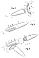
- FIG. 1 shows an application set 1 according to the invention.
- the assembly 1 comprises a gripping member 2, also called handle 2 in the description which follows, at one end 3 of which are presented two arms, preferably flexible, respectively 4 and 5. Arms 4 and 5 are assembled together at a gripping area 6 connected to the end 3 of the handle 2.
- the gripping member 2 has an elongation axis main 8.
- the arms 4 and 5 support an application means 12.
- the handle 2 is detachable from the arms 4 and 5.
- the handle 2 de facto includes a retention means 7 at the level of its end 3 to cooperate with the gripping area 6.
- this means retention 7 is elastic so that it can be fixed and / or detached from arms 4 and 5 reversibly.
- end 3 may include means for cooperating with a retention means presented by zone 6.
- this end 3, defined on the gripping member 2 at the level of a junction with this grip zone 6 can be elastically deformable.
- the end 3 then comprises for example a means forming a spring.
- an advantage of being able to detach a unit formed from the arms 4 and 5 and the application means 12 of the gripping member 2 makes it possible to change the application means 12, in particular when it is worn.
- the used unit is then discarded example.
- a replacement unit with two arms such as 4 and 5 and an application means such as 12 retained between these two arms can then be mounted on the handle 2 naked.
- the units can be different so as to offer different arm positions, or means of applying different structures.
- the structure of the means Application 12 contributes to the shape of the line which will then be reproduced.
- a cabinet with such replacement units may have means of application of different thicknesses, to make it possible to carry out more or less fine lines.
- these replacement units allow avoid enduring the means of application with different products, and including different colors.
- the gripping member 2 comprises a pivot 30 engaged in a housing complementary 31 of the grip zone 6 of the two arms 4 and 5.
- the pivot 30 is erected orthogonally along a pivot axis 34 relative to a surface 32 of the gripping member 2.
- the complementary housing 31 opens at level of a surface 33 of the grip zone 6.
- the surfaces 32 and 33 are respectively complementary so that they can be joined together the other when the pivot 30 is engaged in the housing 31, and so as to tolerate a rotation around this pivot.
- the surfaces 32 and 33 are planar.
- the surfaces 32 and 33 are respectively domed one concave and the other convex.
- this dome can correspond to a hemisphere.
- the two arms 4 and 5 are fixed relative to this area of grip 6 so as to allow a modification of the orientation of these two arm relative to the gripping member 2.
- the surfaces 32 and 33 form an angle other than 90 ° with the main elongation axis 8.
- Both arms do not extend necessarily in a plane, but they are configured so that a passing plane by the application means 12 and the gripping area 6 can be intersecting with the main elongation axis 8 in at least one angular position of the two arms 4 and 5 relative to the gripping member 2.
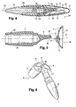
- the two arms 4 and 5 are in a first position arranged in a plane passing through the elongation axis 8 and the pivot axis 34.
- the surfaces 32 and 33 at which the rotation takes place are slightly offset relative to the main elongation axis 8.
- the axis main elongation 8 and the pivot axis 34 intersect at a distance from the surfaces 32 and 33. Therefore, especially insofar as the two arms are not symmetrical to each other, and in particular in the case where the arm 5 is shorter that arm 4, then this first position corresponds to a position minimum bulk, insofar as only the shortest arm 5 exceeds of the gripping member 2 substantially along the axis 8.
- the two arms have been rotated 180 ° relative to the position of Figure 4 and are in a second position while remaining in the plane passing through the elongation axis 8 and the pivot axis 34.
- This second position is different from the first position in the case where the two arms are different from each other.
- the arm 4 longer protrudes from the gripping member 2.
- the arms are configured so that in the first position, the application means 12 extends substantially parallel to the elongation axis 8, while in this second position it extends substantially orthogonally to this axis elongation 8.
- the pivot 30 comprises at at least one groove 50 able to cooperate with at least three grooves such as 51 formed on the inner periphery of the housing 31.
- the groove 50 is complementary to grooves such as 51 to index at least the three positions mentioned above.
- the pivot 30 has two grooves 50 diametrically opposed to cooperate with four grooves 51, the grooves 51 being evenly distributed over the inner periphery of the housing 31.
- a relief is provided on one of the surfaces 32 or 33 to cooperate with recesses complementary provided on the other of surfaces 32 or 33.
- the gripping member 2 is molded in one piece with arms 4 and 5. In this case, it is molded in a at least slightly flexible thermoplastic material.
- Arms 4 and 5 are arched.
- the gripping member 2 is mounted at the level of an outer circumference of this arc.
- the two arms are symmetrical to each other relative to an axis intersecting the grip zone 6, and extending along the main elongation axis 8 of the handle 2.
- the two arms are more symmetrical to each other relative to a plane passing through this axis elongation 8.
- the arms 4 and 5 have a curvature 9, such that the axis 8 is orthogonal to a tangent of this curvature.
- the first arm 4 has a first free end 10.
- the second arm 5 has a second free end 11. In particular, they form an arc, and the ends 10 and 11 can be diametrically opposed.
- the application means 12 is retained between these two ends 10 and 11.
- This application means 12 is preferably elongated and forms a flexible strip for example retained respectively by two articulations 13 and 14 on each ends 10 and 11.
- These joints 13 and 14 can for example pivot along axes respectively orthogonal to the elongation axis 8.
- the application means 12 comprises a boss constituting a protruding element, sensitive during its application, and therefore forming an element touch-sensitive aid in positioning a first point of the application means 12 relatively to the surface to be coated.
- the application means 12 is stretched between the two ends 10 and 11, not provided with articulations, but having only means for each retaining a termination of the application means 12.
- the ends 10 and 11 are provided with slots in which the strip formed by the application means 12 can be retained.
- the set 1 looks like a weapon for firing arrows, the flexible arms corresponding to a bow and the means of application corresponding to the string of this bow.
- the application means 12 can be elastically deformable. In this also, it is not absolutely necessary to provide joints to pivot such as 13 and 14.
- the length of this application means 12 is then modular so as to adapt to the length of the desired line.
- the arms 4 and 5 can also be elastically deformable.
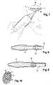
- the user grasps the grip 2 in one of its hands, it has one of the ends 10 or 11 to proximity to a point from which she wants to draw. Then she swivels the device around this first end pressed against the surface to coat, forming a pivot.
- the application means 12 is thus gradually put in contact with the surface to be coated. Given the elongated shape of this application means 12, a line of almost constant thickness is obtained.
- the assembly 1 can come into contact with a curved surface to be coated. In particular, it is adapted to adapt to the morphology of an eyelid generally convex.
- the first end 10, or respectively 11, is arranged at an inner corner of the eyelid, and the hand is moved towards the eyelid so as to position the second end 11, or respectively 10, at an external commissure of this eyelid.
- the application means 12 is preferably coated beforehand with the product. to be applied by means of an ink pad 35.
- This ink pad 35 is by example arranged in communication with a reservoir 15.
- the ink pad 35 is for example, FIGS. 2 and 3, in the shape of a U such that the hollow of the U is presented opposite a slot 16 of the reservoir 15.
- the ink pad 35 is for example obtained from an open cell foam impregnated with the product contained in the reservoir 15 by capillarity.
- the reservoir 15 is provided with a stick or of a piston or of deformable walls so as to be able to compress the product towards ink pad 35.
- the application means 12 can be inserted into this slot 16.
- the reservoir 15 is designed to be able to retain this means of application 12.
- the gripping member 2 is removable, only the application means 12 and a portion of the flexible arms 4 and 5 are inserted into the slot 16.
- the reservoir may also include other retention means 17 to retain the gripping member 2 on the reservoir.
- the tank 15 a by example an elongated shape, the slot 16 being formed along an axis main elongation 18 of the reservoir 15.
- the gripping 2 is mounted on the reservoir 15, so that its axis main elongation 8 is superimposed on the axis 18.
- the end 3 of the handle 2 has means 19 to cooperate with the reservoir retention means 17 15.
- the reservoir 15 then comprises a housing whose opening 22 is defined orthogonally to axis 18, and such that the retention means 7 of the end 3 can be inserted there.
- this housing has on a wall inside a groove to cooperate with a threaded periphery presented by the additional resources 19.
- this slot 16 has a length, relative to axis 18, which is less than the distance between the two ends 10 and 11 of the two flexible arms, ie less than one length at rest of the application means 12.
- the ink pad 35 is disposed at the level of a neck 36 of the reservoir 15.
- the ink pad 35 then closes the neck so as to be in permanent fluid communication with the interior of the reservoir 15 and of the product contained therein.
- the pad 35 is permanently soaked in product.
- the width of the neck 36 is here much less than the length of the application means 12 to be coated.
- the neck 36 has two slots such that 37 diametrically opposite so as to allow the means to slide application 12 between these two slots. Full length of application medium 12 can be slid between these two slots such as 37.
- the ink pad 35 is arranged to be compressed against the means application 12 when it is fully inserted into the hollow of the slots such as 37.
- the ink pad 35 protrudes outside the neck 36, the pad 35 being in fluid communication with the interior of the reservoir 15 and with the product contained therein.
- the pad 35 then has a groove annular to cooperate with a radially prominent annular lip of a inner circumference of the neck 36 to be retained there.
- the buffer 35 can in this case also be slightly crushed, see slightly pressed into the collar 36, when the application against the means of application 12.
- the pad has a length substantially identical to that of the application means 12. Furthermore, to avoid having to move the application means 12 in a slot such as 16 or 37, the neck 36 not necessarily being widened for this need, the pad 35 is then preferably presented on the outer lateral periphery of the neck 36. The neck 36 then has a side window from which the buffer 35 protrudes, this window opening into a trapezoidal section cavity configured for retain the pad 35. The pad 35 is then force-fitted there. In this variant also, the pad 35 remains in fluid communication with the interior of the tank 15. The length of this outer lateral circumference along the axis elongation 18 of the reservoir 15 is substantially equal to the length of the means of application 12.
- this reservoir 15 is provided for be fixed in a cavity 38 of the gripping member 2.
- the neck 36 provided with its ink pad 35 is disposed in this cavity 38.
- the gripping 2 then serves as a closure cap for the reservoir 15.
- the reservoir 15 is inserted at a rear zone of the gripping member 2, opposite to the end 3 at the level of which the arms 4 and 5 are attached.
- the reservoir 15 has on its outer periphery retention means 39 suitable to cooperate with complementary means 40 presented on the periphery inside the cavity 38.
- the retention means 39 is a flange annular capable of snapping into an annular groove 40 of the periphery inside this cavity 38.
- the outer periphery of the neck 36 also includes a rod annular 41 able to abut on the inner periphery of the cavity 38, so as to ensure a tight junction.
- the reservoir 15 is mounted watertight inside the cavity 38.
- a preferred use of such a set 1 is to remove a cap 42 mounted on the gripping member 2, the cap 42 serving to hide the two arms 4 and 5 and the application means 12, in particular when they are in the first position.
- the cap 42 can also serve to maintain the means Application 12 in an environment of constant humidity.
- the cap 42 has a humidifier to prevent drying out applicator means 12.
- the user again stores the reservoir 15 in the gripping member 2, the gripping member 2 being thus ballasted by the reservoir 15, it is therefore more pleasant to handle.
- a cap such as 42 includes a second reservoir forming a reserve of product, for example of a product different from that contained in the reservoir 15.
- This second reservoir is by example presented at the level of the inner periphery of the cap 42, and in this case, in a closed position of the assembly, the application means 12 is maintained in contact with this reserve of product.
- this second tank can only be accessed from the outer periphery of this cap 42. And in this case, the cap must first be released from the grip 2 to allow the application means 12 to be coated with the product of this second tank.
Applications Claiming Priority (2)
| Application Number | Priority Date | Filing Date | Title |
|---|---|---|---|
| FR0304572 | 2003-04-11 | ||
| FR0304572A FR2853506B1 (fr) | 2003-04-11 | 2003-04-11 | Dispositif d'application d'un trait |
Publications (3)
| Publication Number | Publication Date |
|---|---|
| EP1466542A2 true EP1466542A2 (de) | 2004-10-13 |
| EP1466542A3 EP1466542A3 (de) | 2004-12-29 |
| EP1466542B1 EP1466542B1 (de) | 2007-05-09 |
Family
ID=32865420
Family Applications (1)
| Application Number | Title | Priority Date | Filing Date |
|---|---|---|---|
| EP04290975A Expired - Lifetime EP1466542B1 (de) | 2003-04-11 | 2004-04-13 | Auftragsvorrichtung für einen Strich |
Country Status (5)
| Country | Link |
|---|---|
| EP (1) | EP1466542B1 (de) |
| AT (1) | ATE361684T1 (de) |
| DE (1) | DE602004006335T2 (de) |
| ES (1) | ES2287665T3 (de) |
| FR (1) | FR2853506B1 (de) |
Cited By (1)
| Publication number | Priority date | Publication date | Assignee | Title |
|---|---|---|---|---|
| WO2015189527A1 (fr) * | 2014-06-13 | 2015-12-17 | Bourjois | Article de produit cosmetique comportant un timbre |
Citations (7)
| Publication number | Priority date | Publication date | Assignee | Title |
|---|---|---|---|---|
| GB317816A (en) * | 1928-05-23 | 1929-08-23 | William Arthur Hearsey | Means for improving the appearance of the face and features |
| US2136779A (en) * | 1937-11-04 | 1938-11-15 | Henry J Bednar | Eyelash darkener |
| FR947341A (fr) * | 1947-05-28 | 1949-06-29 | Appareils pour cosmétiquer automatiquement les cils | |
| FR2065297A5 (de) * | 1969-10-10 | 1971-07-23 | Fairbanks Wayne Kent | |
| US4483356A (en) * | 1982-08-11 | 1984-11-20 | Kales Donna R | Hand-held lotion applicator |
| US5927295A (en) * | 1997-09-30 | 1999-07-27 | Quinones; Lydia E. | Eyelash comb |
| US6508255B1 (en) * | 2000-10-25 | 2003-01-21 | Color Access, Inc. | Eyeliner applicator |
-
2003
- 2003-04-11 FR FR0304572A patent/FR2853506B1/fr not_active Expired - Fee Related
-
2004
- 2004-04-13 EP EP04290975A patent/EP1466542B1/de not_active Expired - Lifetime
- 2004-04-13 ES ES04290975T patent/ES2287665T3/es not_active Expired - Lifetime
- 2004-04-13 AT AT04290975T patent/ATE361684T1/de not_active IP Right Cessation
- 2004-04-13 DE DE602004006335T patent/DE602004006335T2/de not_active Expired - Lifetime
Patent Citations (7)
| Publication number | Priority date | Publication date | Assignee | Title |
|---|---|---|---|---|
| GB317816A (en) * | 1928-05-23 | 1929-08-23 | William Arthur Hearsey | Means for improving the appearance of the face and features |
| US2136779A (en) * | 1937-11-04 | 1938-11-15 | Henry J Bednar | Eyelash darkener |
| FR947341A (fr) * | 1947-05-28 | 1949-06-29 | Appareils pour cosmétiquer automatiquement les cils | |
| FR2065297A5 (de) * | 1969-10-10 | 1971-07-23 | Fairbanks Wayne Kent | |
| US4483356A (en) * | 1982-08-11 | 1984-11-20 | Kales Donna R | Hand-held lotion applicator |
| US5927295A (en) * | 1997-09-30 | 1999-07-27 | Quinones; Lydia E. | Eyelash comb |
| US6508255B1 (en) * | 2000-10-25 | 2003-01-21 | Color Access, Inc. | Eyeliner applicator |
Cited By (2)
| Publication number | Priority date | Publication date | Assignee | Title |
|---|---|---|---|---|
| WO2015189527A1 (fr) * | 2014-06-13 | 2015-12-17 | Bourjois | Article de produit cosmetique comportant un timbre |
| FR3022124A1 (fr) * | 2014-06-13 | 2015-12-18 | Bourjois | Article de produit cosmetique presentant une zone de contact |
Also Published As
| Publication number | Publication date |
|---|---|
| DE602004006335T2 (de) | 2008-01-10 |
| DE602004006335D1 (de) | 2007-06-21 |
| ES2287665T3 (es) | 2007-12-16 |
| ATE361684T1 (de) | 2007-06-15 |
| EP1466542A3 (de) | 2004-12-29 |
| FR2853506A1 (fr) | 2004-10-15 |
| FR2853506B1 (fr) | 2006-12-08 |
| EP1466542B1 (de) | 2007-05-09 |
Similar Documents
| Publication | Publication Date | Title |
|---|---|---|
| EP1452111B1 (de) | Vorrichtung zum Speichern und Applizieren eines kosmetischen Produktes | |
| EP3420845B1 (de) | Applikatortrichter für kosmetikprodukt, entsprechender applikator und entsprechende applikatoranordnung | |
| EP0916282B1 (de) | Vorrichtung zum Aufbewahren und Auftragen mit einem Behälter, einem ergonomischen Applikator und einem Abstreifer | |
| CA2406362C (fr) | Dispositif d'application d'un produit notamment cosmetique avec un organe d'application amovible | |
| CA2169613C (fr) | Doseur capillaire a fente terminale | |
| CA2311153C (fr) | Applicateur pour l'application d'un produit, et son utilisation pour le transfert du produit sur une surface telle que la peau | |
| EP0474319A2 (de) | Auftragseinheit zum Schminken von Augenwimpern mit einer Mascaramasse und einem befeuchteten Spenderelement | |
| EP0960584B1 (de) | Vorrichtung zum Aufbewahren und Auftragen eines Präparats auf Keratinfasern | |
| EP1053695A2 (de) | Vorrichtung zum Aufbewahren und Auftragen von kosmetischen Produkten, insbesondere für Lippenstift | |
| EP1336353A1 (de) | Applikator mit einem zum Auftragen auf die Haut augebildeten Auftrageelement | |
| FR2753056A1 (fr) | Applicateur de maquillage ou de produit de soin | |
| FR2854779A1 (fr) | Applicateur et dispositif de conditionnement et d'application comportant un tel applicateur | |
| EP1634616A1 (de) | Applikationseinheit mit einem abnehmbaren Applikator | |
| FR3095116A1 (fr) | Applicateur de cosmétique avec des portions flexibles et rigides | |
| EP1228715B1 (de) | Auftrageeinheit, insbesondere eines Schminkproduktes | |
| EP1440629B1 (de) | Applikator zum Auftragen einer Substanz auf einen Teil des menschlichen Körpers | |
| FR3036598A1 (fr) | Dispositif d'application et de massage | |
| US20040258454A1 (en) | Device for application of a line | |
| FR3027778A1 (fr) | Applicateur pour appliquer un produit cosmetique ou de soin | |
| EP0610107A1 (de) | Applikator und Einheit zur Aufnahme und zum Auftragen von Mascara | |
| FR3025986A1 (fr) | Applicateur de produit cosmetique ou de soin | |
| EP1369055B1 (de) | Applikator mit einer Stange, die mit einer Greifvorrichtung durch ein Gelenk verbunden ist | |
| EP1466542B1 (de) | Auftragsvorrichtung für einen Strich | |
| EP1428455B2 (de) | Applikator, insbesondere für Kosmetik | |
| EP1393649B1 (de) | Vorrichtung zum Aufbewahren und Auftragen eines Produktes, insbesondere eines Eyeliners |
Legal Events
| Date | Code | Title | Description |
|---|---|---|---|
| PUAI | Public reference made under article 153(3) epc to a published international application that has entered the european phase |
Free format text: ORIGINAL CODE: 0009012 |
|
| AK | Designated contracting states |
Kind code of ref document: A2 Designated state(s): AT BE BG CH CY CZ DE DK EE ES FI FR GB GR HU IE IT LI LU MC NL PL PT RO SE SI SK TR |
|
| AX | Request for extension of the european patent |
Extension state: AL HR LT LV MK |
|
| PUAL | Search report despatched |
Free format text: ORIGINAL CODE: 0009013 |
|
| AK | Designated contracting states |
Kind code of ref document: A3 Designated state(s): AT BE BG CH CY CZ DE DK EE ES FI FR GB GR HU IE IT LI LU MC NL PL PT RO SE SI SK TR |
|
| AX | Request for extension of the european patent |
Extension state: AL HR LT LV MK |
|
| 17P | Request for examination filed |
Effective date: 20050629 |
|
| AKX | Designation fees paid |
Designated state(s): AT BE BG CH CY CZ DE DK EE ES FI FR GB GR HU IE IT LI LU MC NL PL PT RO SE SI SK TR |
|
| GRAP | Despatch of communication of intention to grant a patent |
Free format text: ORIGINAL CODE: EPIDOSNIGR1 |
|
| GRAS | Grant fee paid |
Free format text: ORIGINAL CODE: EPIDOSNIGR3 |
|
| GRAA | (expected) grant |
Free format text: ORIGINAL CODE: 0009210 |
|
| AK | Designated contracting states |
Kind code of ref document: B1 Designated state(s): AT BE BG CH CY CZ DE DK EE ES FI FR GB GR HU IE IT LI LU MC NL PL PT RO SE SI SK TR |
|
| PG25 | Lapsed in a contracting state [announced via postgrant information from national office to epo] |
Ref country code: FI Free format text: LAPSE BECAUSE OF FAILURE TO SUBMIT A TRANSLATION OF THE DESCRIPTION OR TO PAY THE FEE WITHIN THE PRESCRIBED TIME-LIMIT Effective date: 20070509 |
|
| REG | Reference to a national code |
Ref country code: GB Ref legal event code: FG4D Free format text: NOT ENGLISH |
|
| REG | Reference to a national code |
Ref country code: CH Ref legal event code: EP |
|
| REG | Reference to a national code |
Ref country code: IE Ref legal event code: FG4D Free format text: LANGUAGE OF EP DOCUMENT: FRENCH |
|
| REF | Corresponds to: |
Ref document number: 602004006335 Country of ref document: DE Date of ref document: 20070621 Kind code of ref document: P |
|
| GBT | Gb: translation of ep patent filed (gb section 77(6)(a)/1977) |
Effective date: 20070712 |
|
| PG25 | Lapsed in a contracting state [announced via postgrant information from national office to epo] |
Ref country code: SE Free format text: LAPSE BECAUSE OF FAILURE TO SUBMIT A TRANSLATION OF THE DESCRIPTION OR TO PAY THE FEE WITHIN THE PRESCRIBED TIME-LIMIT Effective date: 20070809 |
|
| NLV1 | Nl: lapsed or annulled due to failure to fulfill the requirements of art. 29p and 29m of the patents act | ||
| PG25 | Lapsed in a contracting state [announced via postgrant information from national office to epo] |
Ref country code: PL Free format text: LAPSE BECAUSE OF FAILURE TO SUBMIT A TRANSLATION OF THE DESCRIPTION OR TO PAY THE FEE WITHIN THE PRESCRIBED TIME-LIMIT Effective date: 20070509 Ref country code: AT Free format text: LAPSE BECAUSE OF FAILURE TO SUBMIT A TRANSLATION OF THE DESCRIPTION OR TO PAY THE FEE WITHIN THE PRESCRIBED TIME-LIMIT Effective date: 20070509 |
|
| REG | Reference to a national code |
Ref country code: ES Ref legal event code: FG2A Ref document number: 2287665 Country of ref document: ES Kind code of ref document: T3 |
|
| REG | Reference to a national code |
Ref country code: IE Ref legal event code: FD4D |
|
| PG25 | Lapsed in a contracting state [announced via postgrant information from national office to epo] |
Ref country code: SI Free format text: LAPSE BECAUSE OF FAILURE TO SUBMIT A TRANSLATION OF THE DESCRIPTION OR TO PAY THE FEE WITHIN THE PRESCRIBED TIME-LIMIT Effective date: 20070509 Ref country code: PT Free format text: LAPSE BECAUSE OF FAILURE TO SUBMIT A TRANSLATION OF THE DESCRIPTION OR TO PAY THE FEE WITHIN THE PRESCRIBED TIME-LIMIT Effective date: 20071009 Ref country code: DK Free format text: LAPSE BECAUSE OF FAILURE TO SUBMIT A TRANSLATION OF THE DESCRIPTION OR TO PAY THE FEE WITHIN THE PRESCRIBED TIME-LIMIT Effective date: 20070509 Ref country code: NL Free format text: LAPSE BECAUSE OF FAILURE TO SUBMIT A TRANSLATION OF THE DESCRIPTION OR TO PAY THE FEE WITHIN THE PRESCRIBED TIME-LIMIT Effective date: 20070509 Ref country code: BG Free format text: LAPSE BECAUSE OF FAILURE TO SUBMIT A TRANSLATION OF THE DESCRIPTION OR TO PAY THE FEE WITHIN THE PRESCRIBED TIME-LIMIT Effective date: 20070809 Ref country code: IE Free format text: LAPSE BECAUSE OF FAILURE TO SUBMIT A TRANSLATION OF THE DESCRIPTION OR TO PAY THE FEE WITHIN THE PRESCRIBED TIME-LIMIT Effective date: 20070509 Ref country code: CZ Free format text: LAPSE BECAUSE OF FAILURE TO SUBMIT A TRANSLATION OF THE DESCRIPTION OR TO PAY THE FEE WITHIN THE PRESCRIBED TIME-LIMIT Effective date: 20070509 |
|
| PG25 | Lapsed in a contracting state [announced via postgrant information from national office to epo] |
Ref country code: SK Free format text: LAPSE BECAUSE OF FAILURE TO SUBMIT A TRANSLATION OF THE DESCRIPTION OR TO PAY THE FEE WITHIN THE PRESCRIBED TIME-LIMIT Effective date: 20070509 |
|
| PLBE | No opposition filed within time limit |
Free format text: ORIGINAL CODE: 0009261 |
|
| STAA | Information on the status of an ep patent application or granted ep patent |
Free format text: STATUS: NO OPPOSITION FILED WITHIN TIME LIMIT |
|
| 26N | No opposition filed |
Effective date: 20080212 |
|
| PG25 | Lapsed in a contracting state [announced via postgrant information from national office to epo] |
Ref country code: GR Free format text: LAPSE BECAUSE OF FAILURE TO SUBMIT A TRANSLATION OF THE DESCRIPTION OR TO PAY THE FEE WITHIN THE PRESCRIBED TIME-LIMIT Effective date: 20070810 |
|
| PG25 | Lapsed in a contracting state [announced via postgrant information from national office to epo] |
Ref country code: RO Free format text: LAPSE BECAUSE OF FAILURE TO SUBMIT A TRANSLATION OF THE DESCRIPTION OR TO PAY THE FEE WITHIN THE PRESCRIBED TIME-LIMIT Effective date: 20070509 |
|
| BERE | Be: lapsed |
Owner name: L'OREAL Effective date: 20080430 |
|
| PG25 | Lapsed in a contracting state [announced via postgrant information from national office to epo] |
Ref country code: MC Free format text: LAPSE BECAUSE OF NON-PAYMENT OF DUE FEES Effective date: 20080430 |
|
| REG | Reference to a national code |
Ref country code: CH Ref legal event code: PL |
|
| PG25 | Lapsed in a contracting state [announced via postgrant information from national office to epo] |
Ref country code: EE Free format text: LAPSE BECAUSE OF FAILURE TO SUBMIT A TRANSLATION OF THE DESCRIPTION OR TO PAY THE FEE WITHIN THE PRESCRIBED TIME-LIMIT Effective date: 20070509 Ref country code: CH Free format text: LAPSE BECAUSE OF NON-PAYMENT OF DUE FEES Effective date: 20080430 Ref country code: LI Free format text: LAPSE BECAUSE OF NON-PAYMENT OF DUE FEES Effective date: 20080430 |
|
| PG25 | Lapsed in a contracting state [announced via postgrant information from national office to epo] |
Ref country code: BE Free format text: LAPSE BECAUSE OF NON-PAYMENT OF DUE FEES Effective date: 20080430 |
|
| PG25 | Lapsed in a contracting state [announced via postgrant information from national office to epo] |
Ref country code: CY Free format text: LAPSE BECAUSE OF FAILURE TO SUBMIT A TRANSLATION OF THE DESCRIPTION OR TO PAY THE FEE WITHIN THE PRESCRIBED TIME-LIMIT Effective date: 20070509 |
|
| PGFP | Annual fee paid to national office [announced via postgrant information from national office to epo] |
Ref country code: GB Payment date: 20100325 Year of fee payment: 7 |
|
| PG25 | Lapsed in a contracting state [announced via postgrant information from national office to epo] |
Ref country code: LU Free format text: LAPSE BECAUSE OF NON-PAYMENT OF DUE FEES Effective date: 20080413 Ref country code: HU Free format text: LAPSE BECAUSE OF FAILURE TO SUBMIT A TRANSLATION OF THE DESCRIPTION OR TO PAY THE FEE WITHIN THE PRESCRIBED TIME-LIMIT Effective date: 20071110 |
|
| PGFP | Annual fee paid to national office [announced via postgrant information from national office to epo] |
Ref country code: ES Payment date: 20100505 Year of fee payment: 7 Ref country code: FR Payment date: 20100521 Year of fee payment: 7 |
|
| PG25 | Lapsed in a contracting state [announced via postgrant information from national office to epo] |
Ref country code: TR Free format text: LAPSE BECAUSE OF FAILURE TO SUBMIT A TRANSLATION OF THE DESCRIPTION OR TO PAY THE FEE WITHIN THE PRESCRIBED TIME-LIMIT Effective date: 20070509 |
|
| PGFP | Annual fee paid to national office [announced via postgrant information from national office to epo] |
Ref country code: DE Payment date: 20100430 Year of fee payment: 7 Ref country code: IT Payment date: 20100417 Year of fee payment: 7 |
|
| GBPC | Gb: european patent ceased through non-payment of renewal fee |
Effective date: 20110413 |
|
| REG | Reference to a national code |
Ref country code: FR Ref legal event code: ST Effective date: 20111230 |
|
| PG25 | Lapsed in a contracting state [announced via postgrant information from national office to epo] |
Ref country code: DE Free format text: LAPSE BECAUSE OF NON-PAYMENT OF DUE FEES Effective date: 20111101 Ref country code: FR Free format text: LAPSE BECAUSE OF NON-PAYMENT OF DUE FEES Effective date: 20110502 |
|
| REG | Reference to a national code |
Ref country code: DE Ref legal event code: R119 Ref document number: 602004006335 Country of ref document: DE Effective date: 20111101 |
|
| PG25 | Lapsed in a contracting state [announced via postgrant information from national office to epo] |
Ref country code: GB Free format text: LAPSE BECAUSE OF NON-PAYMENT OF DUE FEES Effective date: 20110413 Ref country code: IT Free format text: LAPSE BECAUSE OF NON-PAYMENT OF DUE FEES Effective date: 20110413 |
|
| REG | Reference to a national code |
Ref country code: ES Ref legal event code: FD2A Effective date: 20120604 |
|
| PG25 | Lapsed in a contracting state [announced via postgrant information from national office to epo] |
Ref country code: ES Free format text: LAPSE BECAUSE OF NON-PAYMENT OF DUE FEES Effective date: 20110414 |