EP1336353A1 - Applicator comprising an applicator element configured to apply a product to the skin - Google Patents
Applicator comprising an applicator element configured to apply a product to the skin Download PDFInfo
- Publication number
- EP1336353A1 EP1336353A1 EP03290378A EP03290378A EP1336353A1 EP 1336353 A1 EP1336353 A1 EP 1336353A1 EP 03290378 A EP03290378 A EP 03290378A EP 03290378 A EP03290378 A EP 03290378A EP 1336353 A1 EP1336353 A1 EP 1336353A1
- Authority
- EP
- European Patent Office
- Prior art keywords
- applicator
- application element
- skin
- applicator according
- application
- Prior art date
- Legal status (The legal status is an assumption and is not a legal conclusion. Google has not performed a legal analysis and makes no representation as to the accuracy of the status listed.)
- Granted
Links
Images


Classifications
-
- A—HUMAN NECESSITIES
- A45—HAND OR TRAVELLING ARTICLES
- A45D—HAIRDRESSING OR SHAVING EQUIPMENT; EQUIPMENT FOR COSMETICS OR COSMETIC TREATMENTS, e.g. FOR MANICURING OR PEDICURING
- A45D40/00—Casings or accessories specially adapted for storing or handling solid or pasty toiletry or cosmetic substances, e.g. shaving soaps or lipsticks
- A45D40/26—Appliances specially adapted for applying pasty paint, e.g. using roller, using a ball
- A45D40/262—Appliances specially adapted for applying pasty paint, e.g. using roller, using a ball using a brush or the like
- A45D40/265—Appliances specially adapted for applying pasty paint, e.g. using roller, using a ball using a brush or the like connected to the cap of the container
- A45D40/267—Appliances specially adapted for applying pasty paint, e.g. using roller, using a ball using a brush or the like connected to the cap of the container comprising a wiper
Definitions
- the present invention relates to an applicator comprising an element application configured to apply a cosmetic or care product to the skin, especially the eyelids.
- the product flows through the capillary grooves on the end of the spout, the grooves being in permanently recharged with product thanks to the reserve constituted by the product contained in the cavity.
- the flexible plastic or rubbery material is free from a state of surface capable of retaining product.
- applicators comprising a flocked application element are for elsewhere known for making up nails or lips, see for example US 6,033,143.
- Packaging and application devices comprising a wringer and intended for example for making up the eye are known from US 6,220,254.
- the invention aims in particular to meet all or part of the aforementioned needs.
- tip should be understood in a broad sense, as being synonymous with “protruding part”, and each point can have various shapes without that we depart from the scope of the invention, in particular a rounded or flat end and a shape symmetrical of revolution or not.
- the line drawn on the skin can be simple, that is to say include only one single line in the width direction, or be multiple, i.e. include multiple lines across, including being double with two lines distinct substantially parallel.
- the width of the line can thus correspond to the width the single line drawn in the case of a single line or, in the case of a multiple line, in the cumulative width of the lines drawn and the space or spaces devoid of product separating them.
- an applicator which allows a woman to draw different lines without having to change the applicator, choosing the line by moving the applicator over the skin with a chosen orientation and possibly by exerting more or less pressure on the skin with the element application.
- the user can still, if she wishes, modulate, in particular continuously, the thickness of the line along an eyelid, for example for draw a line on the eyelid that is relatively thin at the ends of the eyelid and more thick in the middle.
- the application element may include a flock covering at least partially or entirely each point, to create a surface condition capable of retaining product.
- Product retained between the flocking hairs can be deposited on the skin during use.
- the product deposited on the skin can thus come, for example, only of the reserve of product accumulated in contact with the flocking bristles.
- the application element may also have a flocked free surface in whole, the expression “free surface” designating the entire part of the surface of the element application that can be used for the application.
- the application element can be produced at least partially in a porous material, in particular a felt, a frit or a foam.
- a porous material in particular a felt, a frit or a foam.
- the element application includes a felt, the latter may not be flocked.
- the tips can be configured so that the width of the line drawn on the skin, when the element application is moved with a first orientation relative to the skin, can be substantially double that of the line drawn when the application element is moved with a second orientation relative to the skin.
- the application element may have two spikes having shapes substantially identical or different shapes, in particular different lengths, these two points defining all or part of the surface used for applying the product.
- the application element can comprise at least two spikes configured with so that their free ends are substantially tangent to the same plane, perpendicular to an axis substantially parallel to the direction in which the points extend or, alternatively, comprise at least two points configured so that their free ends are respectively tangent to two distinct planes, perpendicular to said axis.
- the two points can for example be one behind the other, having regard to in the direction of movement of the application element on the skin, when the latter is used to draw a thin line.
- the fact that the ends of the points are offset can to facilitate, if necessary, the drawing of a thin line with the applicator tilted towards the front, possibly allowing one of the points to flex.
- the two tips can touch each other and one of the tips can be supplied with product by the other point.
- the application element may comprise at least one point comprising a substantially cylindrical end portion, in particular cylindrical of revolution, or even at least two points having respective substantially cylindrical portions, in particular cylindrical of revolution, having substantially equal diameters or different.
- the presence of the substantially cylindrical end portion (s) may allow to draw at least one line having a substantially constant thickness which that either the bending of the point or points.
- the application element has at least one groove extending at least over part of its height.
- the aforementioned groove can lead, at one end, between the points.
- Such a groove can allow by example of increasing the quantity of product which the application element can handle, in order to increase the autonomy of the applicator, and supply the application surface with produced when drawing a line.
- Such a groove can further increase the flexibility of the applicator element and may not open out between the points.
- Such a groove can also be used, for example, to build up a reserve of product in the event that the application element is moved while being substantially lying on the skin.
- the application element may include a space between the tips.
- This space can for example be delimited by an edge connecting the two points and having an outwardly directed concavity.
- the application element may in particular have a flattened end which is not perfectly rectangular when viewed along an axis perpendicular to the plane of this end.
- the space formed between the points can be wide enough to allow to flock at least end parts of the tips over their entire periphery.
- the application element can be configured so that, depending on the pressure exerted by the user on the application element, for an orientation of the applicator relative to the skin, the line drawn thereon is a simple line, thin or thick, or a double line.
- the tips can be connected to an intermediate part of the element of application, more rigid than each point, the intermediate part being connected by example to a fitting tip on the rod of the applicator.
- the middle part can include, for example, a cross section enlarging in proximity to the mounting tip.
- the application element may include at least one recess. This last can be large enough to allow all or part of its surface to be flocked inside without being blocked by the glue used to fix the flocking bristles.
- the application element is piece.
- the application element comprises at least two sub-elements of application produced independently of each other and assembled after their manufacturing.
- the two sub-elements can be made of identical materials or different, and each application sub-element may have a tip.
- the application element may be elastically deformable, and the one or more points can, after bending when applying the product on the skin, resume their initial configuration in the absence of external constraints.
- the application element can be attached to the applicator rod or have at least one part made in one piece, in particular by molding, with the rod.
- the rod may be straight and the applicator element may or may not extend in the alignment of the rod, and in particular not to extend entirely in the alignment of the rod.
- the rod can be bent. The fact that the element application and the stem are not both arranged along a straight line make it easier for the user to identify the orientation to be given to the applicator to draw the line of his choice.
- the applicator can be configured, on the one hand, so as to allow a fine line to be drawn when the plane of the elbow formed by the rod, or of the elbow formed by the application element and the rod, is substantially parallel to the direction of displacement of the applicator on the skin and, on the other hand, so as to make it possible to trace a double or thicker line when said plane has a different orientation, being by example substantially perpendicular to the direction of movement.
- the application element can, for example, be made of a material plastic less hard than the material in which the rod is made. So the properties deformation of the rod and of the application element may be different.
- the application element may include a mounting tip intended to be fix in a housing of the rod and a distal part comprising two points whose axes are coplanar, these points connecting to an intermediate part having an axis located in the same plane as the axes of the points and making an angle, for example less than 30 °, with the axis of the mounting nozzle.
- the intermediate part can present, for example, a cross section having two diametrically opposite notches, the bottom of these notches being located in a plane perpendicular to the plane containing the axes points.
- the rod is connected to a end to a gripping member, which may for example be able to serve as closing cap to close a container containing the product.
- Another object of the invention is a device for packaging and application comprising a container containing a product to apply to the skin, especially on the eyelids, and an applicator as defined more high.
- the applicator of such a device can be configured so that it can be removably attached to the container.
- the latter may include a wringer, for example example a block of foam, which may include at least one orifice substantially closed at rest, in the absence of an applicator, for example a slot.
- wringer for example example a block of foam
- Other types wipers can be used without departing from the scope of the present invention, in particular a capillary wringer.
- an applicator which can be characterized by the fact that the application element comprises at least one application surface not reduced to a symmetrical shape of revolution, having a state of surface capable of retaining product, the application surface being capable of coming at least partially in contact with the skin for at least the first and second orientations of the application element relative to the skin, the application surface being configured so that the width of the line drawn on the skin, measured transversely to a direction of movement of the application element on the skin, is different depending on whether the application element is moved on the skin with the first or with the second orientation.
- an applicator to apply a product to the skin comprising at least two flexible tips, directed substantially in the same direction at rest and allowing to draw lines different depending on the orientation of the applicator relative to the skin, the two tips being supported by a rod connected to a gripping member, the two points being directed in a direction making a non-zero angle with the axis of the portion of the rod which is connected to the gripping member.
- Another subject of the invention is a device comprising a container containing a product, an application element integral with the container and having two flexible tips directed substantially in the same steering, the container also serving as a gripping member, the application element having an application surface configured so that according to the orientation of the applicator relative to the skin, at least two lines of different widths can be traced.
- a device comprising a container containing a product, an application element integral with the container, the latter also serving as a gripping member, the applicator element having an application surface configured so that according to the orientation of the applicator relative to the eyelid, at least two lines of different widths can be traced, the application surface being supplied with product from the container by at least one channel formed through the application element.
- the element is moved on the skin so that contact between the application element and the skin is not limited to the tips.
- the width of the line drawn on the skin, especially the eyelid is selected by choosing the orientation of the applicator relative to the skin.
- the method may also include, for example, the step of tracing a double line on the skin by moving the applicator on it with the orientation corresponding, the two lines of the line may have unequal widths.
- a sufficient pressure on the application element to cause it to flex while it is drawing a line on the skin. You can flex the distal part of the element more application to draw a thick line instead of a double line.
- the method can also include the step of moving the element of application substantially lying on the eyelid, so as to use a portion at less of the lateral surface of the applicator element for depositing product.
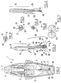
- FIG. 1 shows a packaging device and application 1 comprising a container 2, provided with a neck 3, externally threaded.
- the container 2 comprises a product P, liquid or powder, for example a liquid ink, product P being intended to be applied to the eyelids.
- a wringer 4 constituted for example by a block of polyurethane foam with open cells, split axially, is fixed inside the container 2, under the neck 3.
- the container 2 is closed by a closure cap 5, screwed onto the neck 3.
- This closure cap 5 has a central part 6 able to adjust so watertight in the neck 3.
- the central part 6 is extended downwards by a straight rod 7 of axis X in the example illustrated, provided at its free end with an enlarged part 8 defining a housing allowing the mounting of an application element 10.
- the application element 10, shown in isolation in Figure 3, includes a mounting fitting 15, cylindrical of revolution of axis X, intended to be engaged in the rod housing 7.
- the applicator element 10 further comprises a free part 20 generally elongated along a Y axis, the latter making a non-zero angle ⁇ with the X axis, for example at least about 10 °.
- the free part 20 has two flexible tips 25 which meet to form an intermediate part 21 which is connected to the end piece 15.
- the intermediate part 21 is traversed along its length by two grooves 22 diametrically opposite, each having a substantially cross-sectional shape of a V, the bottoms of the grooves 22 lying on a plane R containing the axis Y, as we can be seen in Figures 4 and 5.
- the cross section of the intermediate part 21 may be of circular or oblong envelope, in particular oblong of larger dimension perpendicular to the plane containing the X and Y axes.
- the grooves 22 can in particular make it possible to retain product by capillarity, so as to form product reserves for the application, the product contained in these grooves 22 which can flow towards the space 29 formed between the points 25.
- the cross section of the intermediate part 21 tends to decrease in distance from the rod 7, as can be seen in FIGS. 5 and 6.
- the tips 25 extend over about a third of the height of the free part 20 from its lower end.
- the tips 25 each have an end portion 26, cylindrical with revolution in the example considered, as can be seen in Figures 3, 8 and 9.
- the points 25 have shapes and dimensions substantially identical. In particular, their free ends are tangent to the same plane K, perpendicular to the Y axis.
- the element application 10 may include points 25 having different lengths.
- the free end of one of the points 25 may be adjacent to a plane K1, and the other tip 25 may have a free end adjacent to a plane K2, distinct from the plane K1, the planes K1 and K2 being perpendicular to the axis Y.
- the application element 10 can for example be in one piece and be made in a thermoplastic material, in particular a thermoplastic elastomer, so at least the end portions 26 of the tips 25 are resiliently deformable and can flex significantly when the applicator is used to draw a thick line.
- the user When the user wishes to draw a thin line on the eyelid, as illustrated in FIG. 11, it can move the application element 10 by orienting it so that the plane defined by the X and Y axes is substantially parallel to the direction of movement of the application element 10, only one of the two points 25 can then come into contact with the eyelid, if the applicator is tilted enough forward.
- the two points 25 can also each come into contact with the eyelid if the applicator is slightly tilted.
- the user can also choose to draw a thicker line. For it, it can move the application element 10 on the eyelid with another orientation, the plane defined by the X and Y axes being not parallel to the direction of movement of the application element, being for example substantially perpendicular thereto.
- the applicator element 10 can bend enough so that the end portions 26 tips 25 lie on the skin, so that the application element 10 leaves on the eyelid a thick line, as illustrated very schematically in Figure 12.
- the intermediate part 21 can be rigid enough not to bend at a right angle while the end portions 26 of the tips 25 are lying on the skin.
- the user can choose to change the orientation of the application element relatively to the eyelid and the pressure exerted while maintaining the contact of the application element 10 with it, in order to continuously modify the width of the line trace on the eyelid.
- FIGS. 14A to 14E show different examples of make-up likely to be obtained with an applicator such as for example the one which has just been described.
- FIG. 14A represents a make-up comprising a thin line
- FIG. 14B a make-up with a thicker line, obtained with a different orientation of the applicator.
- FIG. 14C represents a make-up in which the line drawn on the skin has an increasing then decreasing width, the variation in width being obtained by changing the orientation of the applicator and possibly the pressure on the skin during the application.
- FIG. 14D represents a make-up in which the line is double, the lines being separated from one end to the other of the line.
- the lines can still be join at least one point along the length of the line, for example join at its ends, as shown in Figure 14E.
- the two lines of the double line can be of unequal widths, as illustrated in figure 14F.
- the groove 22 may not open into the space between the points, as illustrated in figure 15.
- the rod 7 is straight, and the inclination of the tips 25 relative to the X axis can allow the user to more easily identify the orientation to be given to the applicator to trace the desired trait.
- This figure shows an applicator comprising a bent rod comprising a portion 7a of axis X, adjacent to the gripping member 5, and a portion 7b of axis Y, adjacent to the application element 10.
- the application element can be identical to that which has just been described or to be different.
- the presence of a bent rod can allow the use of a application element 10 entirely rectilinear with a Y axis parallel to the axis of the portion 7b.
- the container may be provided with a wringer other than a foam block, in particular a block of foam having an orifice closed at rest in the absence of an applicator.
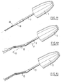
- FIG. 17 shows, by way of example, a device 40 comprising a container 41 containing a product P to be applied, for example an ink liquid.
- the container 41 has a neck 42, externally threaded, and it is provided with a wringer 43, for example made of elastomer.
- the wiper 43 may have a wall 44, substantially cylindrical of revolution, connecting at its upper end to a rim 45 bearing against the edge of the neck 42, and at its lower end to a bottom wall 46 pierced with a central orifice 47, of diameter slightly greater than that of the rod 55 of the applicator.
- the container 41 can be closed by a closure cap 50 comprising a cover 51 in which is fixed an insert 52 receiving the rod 55.
- the latter supports an application element such as for example the application element 10 described in reference to FIG. 1.
- the passage of the application element 10 through the orifice 47 during removal of the applicator removes excess product.
- the applicator element can be entirely aligned with the rod as shown in figure 17.
- the wringer may also have a capillary rupture.
- FIG. 18 shows a device 60 comprising a container provided with a wringer 130 with capillary rupture.
- the applicator may include a rod 7 of larger diameter than that of the example of FIG. 1, in particular devoid of constriction.
- the wiper 130 comprises a tubular part 131 having one end lower 132 and set back from this lower end 132, for example substantially at mid-length of the tubular wall 131, a wiping lip 133 configured to wring the rod 7, defining for example a circular orifice with a diameter close to that of the rod 7, or even slightly lower.
- the lip 133 is not flocked, but one does not exit not within the scope of the present invention when the lip 133 is flocked, as illustrated in Figure 19.
- the accumulation of product under the lip 133 promotes product retention on the wringer.
- the application element may for example include two sub-elements 10a and 10b each comprising a point 25, manufactured independently of each other and assembled after their manufacture, as illustrated in the figure 20.
- the sub-elements 10a and 10b can be made of materials identical or, alternatively, in different materials, in particular having different hardnesses.
- the application element can be produced with a higher number of tips two, without departing from the scope of the present invention.
- FIG. 21 shows an application element 80 comprising three points 81, which can have for example lengths and sections different or be the same.
- the free ends of the three points may not be aligned, being arranged by example like the vertices of an equilateral triangle.
- the application element may also include a portion 105, flocked at the less in its end portion, having an opening 106 having dimensions chosen so that when flocking the portion 105, the glue which is applied to the latter for fixing the flocking bristles does not close the opening 106.
- the portion 105 can form two points 107 and 108 which can be identical or different.
- the two points 107 and 108 are different, the tip 108 being wider than the tip 107, the width being measured in a direction substantially parallel to the axis of the opening 106.
- the applicator element has between edge 107 and 108 an edge 109 concave outward. Thus, a concavity is formed between the tips 107 and 108.
- the application element may also include a part offset by relative to the axis of the rod, as illustrated in Figure 23.
- the application element is fixed to the container that removably contains the product in order to be separated from the container when the drawing of a line on the eyelid.
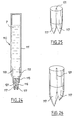
- FIG. 24 shows a device 110 comprising a container 111 containing a product P in the fluid state, for example an ink liquid, this container comprising, at one end, a neck 112 provided with a bead annular 113 allowing the mounting of a nozzle 115 on which is fixed an element 116.
- the latter is made of a felt, for example, and may include two tips 117 with or without flocked end portions.
- the applicator element 116 comprises a channel 121 leading to a end inside the container 111 and at the other end between the points 117. This channel 121 enables the tips 117 to be supplied with product during application.
- the tips can have a rounded tip, as illustrated in Figure 23, or alternatively a tapered end, as illustrated in FIG. 25.
- the application element can have two identical tips, such as illustrated in Figures 24 and 25, or two spikes of unequal length, as illustrated in figure 26.
- the user can for example draw a relatively fine line by moving the device 110 on the eyelid in a first orientation, in which only one of the two points 117 is in contact with the latter, for example.
- She can also choose to draw a line of greater width in moving the device 110 on the eyelid in a second orientation in which the two points 117 come into contact with the eyelid simultaneously, or flex enough to lie down substantially on the skin during application.
- cosmetic product is meant a product as defined by the Directive Council Directive 93/35 / EC of June 14, 1993.
Abstract
Description
La présente invention concerne un applicateur comportant un élément d'application configuré pour appliquer un produit cosmétique ou de soins sur la peau, notamment les paupières.The present invention relates to an applicator comprising an element application configured to apply a cosmetic or care product to the skin, especially the eyelids.
On connaít les crayons permettant de tracer un trait sur la paupière.We know the pencils for drawing a line on the eyelid.
On connaít, par ailleurs, par la demande de brevet FR-A-2 633 256 un ensemble comportant un réservoir contenant un liquide et un applicateur équipé d'un élément d'application souple pour appliquer du produit sur les paupières. L'élément d'application comporte une partie tronconique prolongée, à une extrémité, par une partie cylindrique de révolution. Ces parties tronconique et cylindrique peuvent être floquées, ce qui crée un état de surface capable de retenir du produit. La présence de la partie cylindrique de révolution permet de tracer un trait de largeur uniforme sur la paupière, quelque soit l'orientation de l'applicateur relativement à la paupière.We also know from patent application FR-A-2 633 256 a assembly comprising a reservoir containing a liquid and an applicator equipped with a flexible application element for applying product to the eyelids. The element application has a frustoconical part extended at one end by a part cylindrical of revolution. These frustoconical and cylindrical parts can be flocked, this which creates a surface condition capable of retaining product. The presence of the party cylindrical of revolution makes it possible to draw a line of uniform width on the eyelid, whatever the orientation of the applicator relative to the eyelid.
On connaít encore, par la demande de brevet FR A-2 412 287, un dispositif destiné à permettre le tracé de lignes de maquillage sur les paupières. Ce dispositif comporte un réservoir et un applicateur. Ce dernier comporte une tige à l'extrémité de laquelle est disposé un organe distributeur réalisé dans une matière plastique ou caoutchouteuse souple et se terminant par un bec. Cet organe distributeur comporte une cavité débouchant dans deux rainures capillaires s'étendant jusqu'au bec. Lorsque l'organe distributeur est plongé dans le liquide contenu dans le réservoir, la cavité et les rainures capillaires précitées se chargent en produit. Le tracé des lignes de maquillage s'effectue en déplaçant le bec sur la paupière. Au cours du déplacement, le produit s'écoule par les rainures capillaires sur l'extrémité du bec, les rainures étant en permanence rechargées en produit grâce à la réserve que constitue le produit contenu dans la cavité. La matière plastique ou caoutchouteuse souple est dépourvue d'un état de surface apte à retenir du produit.We still know, from patent application FR A-2 412 287, a device intended to allow the drawing of lines of make-up on the eyelids. These measures includes a reservoir and an applicator. The latter has a rod at the end of which is arranged a distributor member made of a plastic material or soft rubbery and ending in a spout. This distributor organ includes a cavity opening into two capillary grooves extending to the spout. When the dispensing member is immersed in the liquid contained in the reservoir, the cavity and the The aforementioned capillary grooves load with product. The layout of the makeup lines is carried out by moving the beak over the eyelid. During the move, the product flows through the capillary grooves on the end of the spout, the grooves being in permanently recharged with product thanks to the reserve constituted by the product contained in the cavity. The flexible plastic or rubbery material is free from a state of surface capable of retaining product.
D'autres applicateurs comportant un élément d'application floqué sont par ailleurs connus pour le maquillage des ongles ou des lèvres, voir par exemple US 6 033 143. Des dispositifs de conditionnement et d'application comportant un essoreur et destinés par exemple au maquillage de l'oeil sont connus par US 6 220 254. Other applicators comprising a flocked application element are for elsewhere known for making up nails or lips, see for example US 6,033,143. Packaging and application devices comprising a wringer and intended for example for making up the eye are known from US 6,220,254.
Il existe un besoin pour bénéficier d'un applicateur permettant de nouveaux effets de maquillage, par exemple afin de tracer sur la peau des traits ayant des aspects ne permettent pas de réaliser aisément les dispositifs connus par FR-A-2 633 256 ou FR-A-2 412 287.There is a need to benefit from an applicator allowing new makeup effects, for example in order to draw lines on the skin that do not have not allow to easily realize the devices known by FR-A-2 633 256 or FR-A-2 412 287.
Il existe encore un besoin pour augmenter la diversité des maquillages pouvant être obtenus avec un seul applicateur.There is still a need to increase the diversity of makeup obtainable with a single applicator.
L'invention vise notamment à répondre à tout ou partie des besoins précités.The invention aims in particular to meet all or part of the aforementioned needs.
L'invention a pour objet, selon l'un de ses aspects parmi d'autres, un nouvel applicateur, comportant
- un élément d'application configuré pour appliquer un trait de produit sur la peau, notamment sur une paupière,
- an application element configured to apply a line of product on the skin, in particular on an eyelid,
Le terme «pointe» doit être compris dans un sens large, comme étant synonyme de « partie en saillie », et chaque pointe peut avoir des formes diverses sans que l'on sorte du cadre de l'invention, notamment un bout arrondi ou plan et une forme symétrique de révolution ou non.The term "tip" should be understood in a broad sense, as being synonymous with "protruding part", and each point can have various shapes without that we depart from the scope of the invention, in particular a rounded or flat end and a shape symmetrical of revolution or not.
Le trait tracé sur la peau peut être simple, c'est-à-dire ne comporter qu'une seule ligne dans le sens de la largeur, ou encore être multiple, c'est-à-dire comporter plusieurs lignes dans le sens de la largeur, notamment être double avec deux lignes distinctes sensiblement parallèles. La largeur du trait peut ainsi correspondre à la largeur de l'unique ligne tracée dans le cas d'un trait simple ou, dans le cas d'un trait multiple, à la largeur cumulée des lignes tracées et du ou des espaces dépourvus de produit séparant celles-ci.The line drawn on the skin can be simple, that is to say include only one single line in the width direction, or be multiple, i.e. include multiple lines across, including being double with two lines distinct substantially parallel. The width of the line can thus correspond to the width the single line drawn in the case of a single line or, in the case of a multiple line, in the cumulative width of the lines drawn and the space or spaces devoid of product separating them.
Grâce à l'invention, on peut bénéficier d'un applicateur qui permette à une femme de tracer des traits différents sans avoir à changer d'applicateur, le choix du trait s'effectuant en déplaçant l'applicateur sur la peau avec une orientation choisie et éventuellement en exerçant une pression plus ou moins grande sur la peau avec l'élément d'application. Thanks to the invention, one can benefit from an applicator which allows a woman to draw different lines without having to change the applicator, choosing the line by moving the applicator over the skin with a chosen orientation and possibly by exerting more or less pressure on the skin with the element application.
Avec un tel applicateur, l'utilisatrice peut encore, si elle le souhaite, moduler, notamment en continu, l'épaisseur du trait le long d'une paupière, par exemple pour tracer sur la paupière un trait qui est relativement fin aux extrémités de celle-ci et plus épais en son milieu.With such an applicator, the user can still, if she wishes, modulate, in particular continuously, the thickness of the line along an eyelid, for example for draw a line on the eyelid that is relatively thin at the ends of the eyelid and more thick in the middle.
L'élément d'application peut comporter un flocage recouvrant au moins partiellement ou en totalité chaque pointe, pour créer un état de surface apte à retenir du produit. Du produit retenu entre les poils du flocage peut se déposer sur la peau lors de l'utilisation. Le produit déposé sur la peau peut ainsi provenir, par exemple, uniquement de la réserve de produit accumulée au contact des poils du flocage.The application element may include a flock covering at least partially or entirely each point, to create a surface condition capable of retaining product. Product retained between the flocking hairs can be deposited on the skin during use. The product deposited on the skin can thus come, for example, only of the reserve of product accumulated in contact with the flocking bristles.
L'élément d'application peut encore présenter une surface libre floquée en totalité, l'expression « surface libre » désignant toute la partie de la surface de l'élément d'application pouvant servir à l'application.The application element may also have a flocked free surface in whole, the expression “free surface” designating the entire part of the surface of the element application that can be used for the application.
L'élément d'application peut être réalisé au moins partiellement dans un matériau poreux, notamment un feutre, un fritté ou une mousse. Lorsque l'élément d'application comporte un feutre, ce dernier peut ne pas être floqué.The application element can be produced at least partially in a porous material, in particular a felt, a frit or a foam. When the element application includes a felt, the latter may not be flocked.
Dans un exemple de mise en oeuvre de l'invention, les pointes peuvent être configurées de manière à ce que la largeur du trait tracé sur la peau, lorsque l'élément d'application est déplacé avec une première orientation relativement à la peau, puisse être sensiblement le double de celle du trait tracé lorsque l'élément d'application est déplacé avec une deuxième orientation relativement à la peau.In an exemplary implementation of the invention, the tips can be configured so that the width of the line drawn on the skin, when the element application is moved with a first orientation relative to the skin, can be substantially double that of the line drawn when the application element is moved with a second orientation relative to the skin.
L'élément d'application peut comporter deux pointes ayant des formes sensiblement identiques ou des formes différentes, notamment des longueurs différentes, ces deux pointes définissant tout ou partie de la surface servant à l'application du produit.The application element may have two spikes having shapes substantially identical or different shapes, in particular different lengths, these two points defining all or part of the surface used for applying the product.
L'élément d'application peut comporter au moins deux pointes configurées de manière à ce que leurs extrémités libres soient sensiblement tangentes à un même plan, perpendiculaire à un axe sensiblement parallèle à la direction selon laquelle les pointes s'étendent ou, en variante, comporter au moins deux pointes configurées de manière à ce que leurs extrémités libres soient respectivement tangentes à deux plans distincts, perpendiculaires audit axe.The application element can comprise at least two spikes configured with so that their free ends are substantially tangent to the same plane, perpendicular to an axis substantially parallel to the direction in which the points extend or, alternatively, comprise at least two points configured so that their free ends are respectively tangent to two distinct planes, perpendicular to said axis.
Les deux pointes peuvent par exemple se situer l'une derrière l'autre, eu égard au sens de déplacement de l'élément d'application sur la peau, lorsque ce dernier est utilisé pour tracer un trait fin. Le fait que les extrémités des pointes soient décalées peut permettre de faciliter, le cas échéant, le dessin d'un fin trait avec l'applicateur incliné vers l'avant, en permettant éventuellement à l'une des pointes de fléchir. Eventuellement, les deux pointes peuvent se toucher et l'une des pointes peut être alimentée en produit par l'autre pointe.The two points can for example be one behind the other, having regard to in the direction of movement of the application element on the skin, when the latter is used to draw a thin line. The fact that the ends of the points are offset can to facilitate, if necessary, the drawing of a thin line with the applicator tilted towards the front, possibly allowing one of the points to flex. Eventually, the two tips can touch each other and one of the tips can be supplied with product by the other point.
L'élément d'application peut comporter au moins une pointe comportant une portion d'extrémité sensiblement cylindrique, notamment cylindrique de révolution, voire au moins deux pointes comportant des portions respectives sensiblement cylindriques, notamment cylindrique de révolution, ayant des diamètres sensiblement égaux ou différents. La présence de la ou des portions d'extrémité sensiblement cylindriques peut permettre de tracer au moins une ligne ayant une épaisseur sensiblement constante quelle que soit la flexion de la ou des pointes.The application element may comprise at least one point comprising a substantially cylindrical end portion, in particular cylindrical of revolution, or even at least two points having respective substantially cylindrical portions, in particular cylindrical of revolution, having substantially equal diameters or different. The presence of the substantially cylindrical end portion (s) may allow to draw at least one line having a substantially constant thickness which that either the bending of the point or points.
Dans un exemple de mise en oeuvre de l'invention, l'élément d'application comporte au moins une rainure s'étendant au moins sur une partie de sa hauteur. Lorsque l'élément d'application comporte au moins deux pointes, la rainure précitée peut déboucher, à une extrémité, entre les pointes. Une telle rainure peut permettre par exemple d'accroítre la quantité de produit dont peut se charger l'élément d'application, afin d'augmenter l'autonomie de l'applicateur, et alimenter la surface d'application en produit lors du tracé d'un trait. Une telle rainure peut permettre encore d'accroítre la flexibilité de l'élément d'application et peut ne pas déboucher entre les pointes. Une telle rainure peut encore servir, par exemple, à constituer une réserve de produit pour le cas où l'élément d'application est déplacé en étant sensiblement couché sur la peau.In an exemplary implementation of the invention, the application element has at least one groove extending at least over part of its height. When the application element comprises at least two points, the aforementioned groove can lead, at one end, between the points. Such a groove can allow by example of increasing the quantity of product which the application element can handle, in order to increase the autonomy of the applicator, and supply the application surface with produced when drawing a line. Such a groove can further increase the flexibility of the applicator element and may not open out between the points. Such a groove can also be used, for example, to build up a reserve of product in the event that the application element is moved while being substantially lying on the skin.
L'élément d'application peut comporter un espace entre les pointes.The application element may include a space between the tips.
Cet espace peut par exemple être délimité par un bord reliant les deux pointes et ayant une concavité dirigée vers l'extérieur.This space can for example be delimited by an edge connecting the two points and having an outwardly directed concavity.
L'élément d'application peut notamment présenter une extrémité aplatie non parfaitement rectangulaire lorsqu'il est observé suivant un axe perpendiculaire au plan de cette extrémité.The application element may in particular have a flattened end which is not perfectly rectangular when viewed along an axis perpendicular to the plane of this end.
L'espace formé entre les pointes peut être suffisamment large pour permettre de floquer au moins des parties d'extrémité des pointes sur toute leur périphérie.The space formed between the points can be wide enough to allow to flock at least end parts of the tips over their entire periphery.
L'élément d'application peut être configuré de manière à ce que, selon la pression exercée par l'utilisatrice sur l'élément d'application, pour une orientation de l'applicateur relativement à la peau, le trait tracé sur celle-ci soit un trait simple, fin ou épais, ou un trait double.The application element can be configured so that, depending on the pressure exerted by the user on the application element, for an orientation of the applicator relative to the skin, the line drawn thereon is a simple line, thin or thick, or a double line.
Les pointes peuvent se raccorder à une partie intermédiaire de l'élément d'application, plus rigide que chaque pointe, la partie intermédiaire se raccordant par exemple à un embout de montage sur la tige de l'applicateur. La partie intermédiaire peut comporter, par exemple, une section transversale s'agrandissant en rapprochement de l'embout de montage.The tips can be connected to an intermediate part of the element of application, more rigid than each point, the intermediate part being connected by example to a fitting tip on the rod of the applicator. The middle part can include, for example, a cross section enlarging in proximity to the mounting tip.
L'élément d'application peut comporter au moins un évidement. Ce dernier peut être suffisamment grand pour permettre de floquer tout ou partie de sa surface intérieure sans être obturé par la colle utilisée pour fixer les poils de flocage.The application element may include at least one recess. This last can be large enough to allow all or part of its surface to be flocked inside without being blocked by the glue used to fix the flocking bristles.
Dans un exemple de mise en oeuvre de l'invention, l'élément d'application est monobloc.In an exemplary implementation of the invention, the application element is piece.
Dans une variante, l'élément d'application comporte au moins deux sous-éléments d'application fabriqués indépendamment l'un de l'autre et réunis après leur fabrication. Les deux sous-éléments peuvent être réalisés dans des matériaux identiques ou différents, et chaque sous-élément d'application peut comporter une pointe.In a variant, the application element comprises at least two sub-elements of application produced independently of each other and assembled after their manufacturing. The two sub-elements can be made of identical materials or different, and each application sub-element may have a tip.
L'élément d'application peut être élastiquement déformable, et la ou les pointes peuvent, après flexion lors de l'application du produit sur la peau, reprendre leur configuration initiale en l'absence de contraintes externes.The application element may be elastically deformable, and the one or more points can, after bending when applying the product on the skin, resume their initial configuration in the absence of external constraints.
Dans un exemple de mise en oeuvre de l'invention, l'élément d'application peut être rapporté sur la tige de l'applicateur ou comporter au moins une partie réalisée d'un seul tenant, notamment par moulage, avec la tige.In an exemplary implementation of the invention, the application element can be attached to the applicator rod or have at least one part made in one piece, in particular by molding, with the rod.
La tige peut être rectiligne et l'élément d'application s'étendre ou non dans l'alignement de la tige, et notamment ne pas s'étendre tout entier dans l'alignement de la tige. En variante ou additionnellement, la tige peut être coudée. Le fait que l'élément d'application et la tige ne soient pas tout deux disposés le long d'une droite peut permettre à l'utilisatrice de repérer plus facilement l'orientation à donner à l'applicateur pour tracer le trait de son choix.The rod may be straight and the applicator element may or may not extend in the alignment of the rod, and in particular not to extend entirely in the alignment of the rod. Alternatively or additionally, the rod can be bent. The fact that the element application and the stem are not both arranged along a straight line make it easier for the user to identify the orientation to be given to the applicator to draw the line of his choice.
Ainsi, par exemple, l'applicateur peut être configuré, d'une part, de manière à permettre de tracer un trait fin lorsque le plan du coude formé par la tige, ou du coude formé par l'élément d'application et la tige, est sensiblement parallèle à la direction de déplacement de l'applicateur sur la peau et, d'autre part, de manière à permettre de tracer un trait double ou plus épais lorsque ledit plan a une orientation différente, étant par exemple sensiblement perpendiculaire à la direction de déplacement.Thus, for example, the applicator can be configured, on the one hand, so as to allow a fine line to be drawn when the plane of the elbow formed by the rod, or of the elbow formed by the application element and the rod, is substantially parallel to the direction of displacement of the applicator on the skin and, on the other hand, so as to make it possible to trace a double or thicker line when said plane has a different orientation, being by example substantially perpendicular to the direction of movement.
L'élément d'application peut, par exemple, être réalisé dans une matière plastique moins dure que la matière dans laquelle est réalisée la tige. Ainsi les propriétés de déformation de la tige et de l'élément d'application peuvent être différentes.The application element can, for example, be made of a material plastic less hard than the material in which the rod is made. So the properties deformation of the rod and of the application element may be different.
L'élément d'application peut comporter un embout de montage destiné à se fixer dans un logement de la tige et une partie distale comportant deux pointes dont les axes sont coplanaires, ces pointes se raccordant à une partie intermédiaire ayant un axe situé dans le même plan que les axes des pointes et faisant un angle, par exemple inférieur à 30°, avec l'axe de l'embout de montage. La partie intermédiaire peut présenter, par exemple, une section transversale ayant deux encoches diamétralement opposées, le fond de ces encoches étant situé dans un plan perpendiculaire au plan contenant les axes des pointes.The application element may include a mounting tip intended to be fix in a housing of the rod and a distal part comprising two points whose axes are coplanar, these points connecting to an intermediate part having an axis located in the same plane as the axes of the points and making an angle, for example less than 30 °, with the axis of the mounting nozzle. The intermediate part can present, for example, a cross section having two diametrically opposite notches, the bottom of these notches being located in a plane perpendicular to the plane containing the axes points.
Dans un exemple de mise en oeuvre de l'invention, la tige est reliée à une extrémité à un organe de préhension, celui-ci pouvant par exemple être apte à servir de capuchon de fermeture pour fermer un récipient contenant le produit.In an exemplary implementation of the invention, the rod is connected to a end to a gripping member, which may for example be able to serve as closing cap to close a container containing the product.
L'invention a encore pour objet, selon un autre de ses aspects, un dispositif de conditionnement et d'application comportant un récipient contenant un produit à appliquer sur la peau, notamment sur les paupières, et un applicateur tel que défini plus haut.Another object of the invention, according to another of its aspects, is a device for packaging and application comprising a container containing a product to apply to the skin, especially on the eyelids, and an applicator as defined more high.
L'applicateur d'un tel dispositif peut être configuré de manière à pouvoir être fixé de manière amovible sur le récipient. Ce dernier peut comporter un essoreur, par exemple un bloc de mousse, celui-ci pouvant comporter au moins un orifice sensiblement fermé au repos, en l'absence d'applicateur, par exemple une fente. D'autres types d'essoreurs peuvent être utilisés sans que l'on sorte du cadre de la présente invention, notamment un essoreur à rupture capillaire.The applicator of such a device can be configured so that it can be removably attached to the container. The latter may include a wringer, for example example a block of foam, which may include at least one orifice substantially closed at rest, in the absence of an applicator, for example a slot. Other types wipers can be used without departing from the scope of the present invention, in particular a capillary wringer.
L'invention a encore pour objet, selon un autre de ses aspects, un applicateur pouvant se caractériser par le fait que l'élément d'application comporte au moins une surface d'application non réduite à une forme symétrique de révolution, ayant un état de surface apte à retenir du produit, la surface d'application étant apte à venir au moins partiellement au contact de la peau pour au moins des première et deuxième orientations de l'élément d'application relativement à la peau, la surface d'application étant configurée de telle sorte que la largeur du trait tracé sur la peau, mesurée transversalement à une direction de déplacement de l'élément d'application sur la peau, soit différente selon que l'élément d'application est déplacé sur la peau avec la première ou avec la deuxième orientation.Another subject of the invention, according to another of its aspects, is an applicator which can be characterized by the fact that the application element comprises at least one application surface not reduced to a symmetrical shape of revolution, having a state of surface capable of retaining product, the application surface being capable of coming at least partially in contact with the skin for at least the first and second orientations of the application element relative to the skin, the application surface being configured so that the width of the line drawn on the skin, measured transversely to a direction of movement of the application element on the skin, is different depending on whether the application element is moved on the skin with the first or with the second orientation.
L'invention a encore pour objet, selon un autre de ses aspects, un applicateur pour appliquer un produit sur la peau, comportant au moins deux pointes flexibles, dirigées sensiblement dans la même direction au repos et permettant de tracer des traits différents selon l'orientation de l'applicateur relativement à la peau, les deux pointes étant supportées par une tige reliée à un organe de préhension, les deux pointes étant dirigées dans une direction faisant un angle non nul avec l'axe de la portion de la tige qui se raccorde à l'organe de préhension.Another subject of the invention, according to another of its aspects, is an applicator to apply a product to the skin, comprising at least two flexible tips, directed substantially in the same direction at rest and allowing to draw lines different depending on the orientation of the applicator relative to the skin, the two tips being supported by a rod connected to a gripping member, the two points being directed in a direction making a non-zero angle with the axis of the portion of the rod which is connected to the gripping member.
L'invention a encore pour objet, selon un autre de ses aspects, un dispositif comportant un récipient contenant un produit, un élément d'application solidaire du récipient et comportant deux pointes flexibles dirigées sensiblement dans la même direction, le récipient servant également d'organe de préhension, l'élément d'application ayant une surface d'application configurée de telle sorte que selon l'orientation de l'applicateur relativement à la peau, au moins deux traits de largeurs différentes puissent être tracés.Another subject of the invention, according to another of its aspects, is a device comprising a container containing a product, an application element integral with the container and having two flexible tips directed substantially in the same steering, the container also serving as a gripping member, the application element having an application surface configured so that according to the orientation of the applicator relative to the skin, at least two lines of different widths can be traced.
L'invention a encore pour objet, selon un autre de ses aspects, un dispositif comportant un récipient contenant un produit, un élément d'application solidaire du récipient, ce dernier servant également d'organe de préhension, l'élément d'application ayant une surface d'application configurée de telle sorte que selon l'orientation de l'applicateur relativement à la paupière, au moins deux traits de largeurs différentes puissent être tracés, la surface d'application étant alimentée en produit provenant du récipient par au moins un canal réalisé à travers l'élément d'application.Another subject of the invention, according to another of its aspects, is a device comprising a container containing a product, an application element integral with the container, the latter also serving as a gripping member, the applicator element having an application surface configured so that according to the orientation of the applicator relative to the eyelid, at least two lines of different widths can be traced, the application surface being supplied with product from the container by at least one channel formed through the application element.
L'invention a encore pour objet, selon un autre de ses aspects, un procédé de maquillage de la peau, notamment de la paupière, ce procédé étant caractérisé par le fait qu'il comporte les étapes suivantes :
- fournir l'un des applicateurs tels que définis plus haut,
- tracer un trait sur la peau, notamment la paupière, en déplaçant l'applicateur sur celle-ci.
- provide one of the applicators as defined above,
- draw a line on the skin, especially the eyelid, by moving the applicator over it.
Dans un exemple de mise en oeuvre du procédé, on déplace l'élément d'application sur la peau de manière à ce que le contact entre l'élément d'application et la peau ne soit pas limité aux pointes.In an example of implementation of the method, the element is moved on the skin so that contact between the application element and the skin is not limited to the tips.
Dans un exemple de mise en oeuvre du procédé, la largeur du trait tracé sur la peau, notamment la paupière, est sélectionnée en choisissant l'orientation de l'applicateur relativement à la peau.In an example of implementation of the method, the width of the line drawn on the skin, especially the eyelid, is selected by choosing the orientation of the applicator relative to the skin.
Toujours dans un exemple de mise en oeuvre du procédé, on change l'orientation de l'applicateur relativement à la peau, tout en maintenant le contact de l'élément d'application avec la peau, afin de modifier, par exemple, d'une manière sensiblement continue, la largeur du trait tracé sur la peau.Still in an example of implementation of the process, we change the orientation of the applicator relative to the skin, while maintaining the contact of the application element with the skin, in order to modify, for example, in a way substantially continuous, the width of the line drawn on the skin.
Le procédé peut encore comporter, par exemple, l'étape consistant à tracer un trait double sur la peau en déplaçant l'applicateur sur celle-ci avec l'orientation correspondante, les deux lignes du trait pouvant présenter des largeurs inégales.The method may also include, for example, the step of tracing a double line on the skin by moving the applicator on it with the orientation corresponding, the two lines of the line may have unequal widths.
Toujours selon un exemple de mise en oeuvre du procédé, on exerce une pression suffisante sur l'élément d'application pour le faire fléchir alors que celui-ci trace un trait sur la peau. On peut faire fléchir davantage la partie distale de l'élément d'application pour tracer un trait épais au lieu d'un trait double.Still according to an example of implementation of the method, a sufficient pressure on the application element to cause it to flex while it is drawing a line on the skin. You can flex the distal part of the element more application to draw a thick line instead of a double line.
Le procédé peut encore comporter, par exemple, les étapes suivantes :
- déplacer l'applicateur sur la paupière dans une région d'extrémité de celle-ci, de manière à tracer un trait fin, avec une première orientation de l'applicateur relativement à la paupière,
- déplacer l'applicateur dans une région centrale de la paupière, avec une deuxième orientation de l'applicateur relativement à la paupière, de manière à tracer un trait plus large,
- déplacer l'applicateur sur la paupière dans une région d'extrémité de celle-ci avec une nouvelle orientation, de manière à tracer à nouveau un trait fin.
- move the applicator on the eyelid in an end region thereof, so as to draw a fine line, with a first orientation of the applicator relative to the eyelid,
- move the applicator in a central region of the eyelid, with a second orientation of the applicator relative to the eyelid, so as to draw a wider line,
- move the applicator on the eyelid in an end region thereof with a new orientation, so as to draw a thin line again.
Le procédé peut encore comporter l'étape consistant à déplacer l'élément d'application sensiblement couché sur la paupière, de manière à utiliser une portion au moins de la surface latérale de l'élément d'application pour déposer du produit.The method can also include the step of moving the element of application substantially lying on the eyelid, so as to use a portion at less of the lateral surface of the applicator element for depositing product.
La présente invention pourra être mieux comprise à la lecture de la description détaillée qui va suivre, d'exemples de mise en oeuvre non limitatifs, et à l'examen du dessin annexé, sur lequel :
- la figure 1 est une vue schématique et partielle, en coupe axiale, d'un dispositif de conditionnement et d'application conforme à un premier exemple de mise en oeuvre de l'invention,
- la figure 2 représente isolément, de manière schématique et partielle, en perspective, l'applicateur du dispositif de la figure 1,
- la figure 3 est une vue schématique et partielle, de côté, de l'élément d'application de l'applicateur de la figure 2, avant sa mise en place dans la tige de l'applicateur,
- la figure 4 est une coupe axiale, schématique et partielle, suivant IV-IV, de l'élément d'application de la figure 3,
- la figure 5 est une coupe transversale schématique et partielle, suivant V-V, de l'élément d'application de la figure 3,
- la figure 6 est une coupe transversale, schématique et partielle, suivant VI-VI, de l'élément d'application de la figure 3,
- la figure 7 est une coupe transversale, schématique et partielle, agrandie, suivant VII-VII, de l'élément d'application de la figure 3,
- la figure 8 est une coupe transversale, schématique et partielle, suivant VIII-VIII, d'une pointe de l'élément d'application de la figure 3,
- la figure 9 est une vue schématique et partielle, de dessous, de l'élément d'application de la figure 3,
- la figure 10 représente schématiquement et partiellement, les pointes d'un élément d'application correspondant à une variante de la figure 3,
- les figures 11 à 13 illustrent schématiquement trois manières différentes, parmi d'autres, d'appliquer du produit sur une paupière au moyen de l'applicateur du dispositif de la figure 1,
- les figures 14A à 14F illustrent différents exemples de maquillage, parmi d'autres, pouvant être obtenus avec un applicateur tel que par exemple celui de la figure 1,
- la figure 15 représente isolément et partiellement une variante d'élément d'application,
- les figures 16 à 18 représentent schématiquement et partiellement, en coupe axiale, des dispositifs conformes à d'autres exemples de mise en oeuvre de l'invention,
- la figure 19 représente isolément et partiellement une variante d'essoreur à rupture capillaire,
- les figures 20 à 23 représentent schématiquement et partiellement, en perspective, des variantes d'élément d'application,
- la figure 24 représente schématiquement et partiellement, en coupe axiale, un dispositif conforme à un autre exemple de mise en oeuvre de l'invention, et
- les figures 25 et 26 sont des vues schématiques et partielles, en perspective, de variantes d'élément d'application.
- FIG. 1 is a schematic and partial view, in axial section, of a packaging and application device according to a first example of implementation of the invention,
- FIG. 2 represents in isolation, schematically and partially, in perspective, the applicator of the device of FIG. 1,
- FIG. 3 is a schematic and partial view, from the side, of the applicator element of the applicator of FIG. 2, before it is placed in the stem of the applicator,
- FIG. 4 is an axial, schematic and partial section, along IV-IV, of the application element of FIG. 3,
- FIG. 5 is a schematic and partial cross section, along VV, of the application element of FIG. 3,
- FIG. 6 is a schematic and partial cross section, along VI-VI, of the application element of FIG. 3,
- FIG. 7 is an enlarged, schematic and partial cross-section, along line VII-VII, of the application element of FIG. 3,
- FIG. 8 is a schematic and partial cross section, along VIII-VIII, of a tip of the application element of FIG. 3,
- FIG. 9 is a schematic and partial view, from below, of the application element of FIG. 3,
- FIG. 10 schematically and partially represents the tips of an application element corresponding to a variant of FIG. 3,
- FIGS. 11 to 13 schematically illustrate three different ways, among others, of applying product to an eyelid by means of the applicator of the device of FIG. 1,
- FIGS. 14A to 14F illustrate various examples of make-up, among others, which can be obtained with an applicator such as for example that of FIG. 1,
- FIG. 15 represents in isolation and partially a variant of an application element,
- FIGS. 16 to 18 schematically and partially represent, in axial section, devices in accordance with other examples of implementation of the invention,
- FIG. 19 represents in isolation and partially a variant of a wiper with capillary rupture,
- FIGS. 20 to 23 schematically and partially represent, in perspective, variants of the application element,
- FIG. 24 schematically and partially shows, in axial section, a device according to another example of implementation of the invention, and
- Figures 25 and 26 are schematic and partial perspective views of alternative application elements.
On a représenté sur la figure 1 un dispositif de conditionnement et
d'application 1 comportant un récipient 2, pourvu d'un col 3, fileté extérieurement.FIG. 1 shows a packaging device and
Le récipient 2 comporte un produit P, liquide ou pulvérulent, par exemple une
encre liquide, le produit P étant destiné à être appliqué sur les paupières.The
Un essoreur 4, constitué par exemple par un bloc de mousse de polyuréthane
à cellules ouvertes, fendu axialement, est fixé à l'intérieur du récipient 2, sous le col 3.A wringer 4, constituted for example by a block of polyurethane foam
with open cells, split axially, is fixed inside the
Le récipient 2 est fermé par un capuchon de fermeture 5, vissé sur le col 3. Ce
capuchon de fermeture 5 comporte une partie centrale 6 apte à s'ajuster de manière
étanche dans le col 3. La partie centrale 6 se prolonge vers le bas par une tige 7, rectiligne
d'axe X dans l'exemple illustré, pourvue à son extrémité libre d'une partie élargie 8
définissant un logement permettant le montage d'un élément d'application 10.The
L'élément d'application 10, représenté isolément sur la figure 3, comporte un
embout de montage 15, cylindrique de révolution d'axe X, destiné à être engagé dans le
logement de la tige 7.The
L'élément d'application 10 comporte, en outre, une partie libre 20
généralement allongée selon un axe Y, ce dernier faisant un angle α non nul avec l'axe X,
par exemple d'au moins 10° environ. La partie libre 20 comporte deux pointes flexibles
25 qui se rejoignent pour former une partie intermédiaire 21 se raccordant à l'embout 15.The
La partie intermédiaire 21 est parcourue sur sa longueur par deux rainures 22
diamétralement opposées, ayant en section transversale chacune sensiblement la forme
d'un V, les fonds des rainures 22 se situant sur un plan R contenant l'axe Y, comme on
peut le voir sur les figures 4 et 5. La section transversale de la partie intermédiaire 21
peut être d'enveloppe circulaire ou oblongue, notamment oblongue de plus grande
dimension perpendiculaire au plan contenant les axes X et Y.The
Les rainures 22 peuvent permettre notamment de retenir du produit par
capillarité, de manière à former des réserves de produit pour l'application, le produit
contenu dans ces rainures 22 pouvant s'écouler vers l'espace 29 formé entre les pointes
25.The
La section transversale de la partie intermédiaire 21 tend à diminuer en
éloignement de la tige 7, comme on peut le voir sur les figures 5 et 6.The cross section of the
Dans l'exemple illustré, les pointes 25 s'étendent sur un tiers environ de la
hauteur de la partie libre 20 à partir de son extrémité inférieure.In the example illustrated, the
Les pointes 25 comportent chacune une portion d'extrémité 26, cylindrique de
révolution dans l'exemple considéré, comme on peut le voir sur les figures 3, 8 et 9.The
Ces portions d'extrémité 26 sont entièrement recouvertes par un flocage 28.These
Dans l'exemple de la figure 3, les pointes 25 ont des formes et dimensions
sensiblement identiques. En particulier, leurs extrémités libres sont tangentes à un même
plan K, perpendiculaire à l'axe Y.In the example of FIG. 3, the
On ne sort pas du cadre de la présente invention en réalisant des pointes ayant
des formes et dimensions différentes. Ainsi, comme illustré sur la figure 10, l'élément
d'application 10 peut comporter des pointes 25 ayant des longueurs différentes.
L'extrémité libre de l'une des pointes 25 peut être adjacente à un plan K1, et l'autre
pointe 25 peut présenter une extrémité libre adjacente à un plan K2, distinct du plan K1,
les plans K1 et K2 étant perpendiculaires à l'axe Y.It is not beyond the scope of the present invention to produce points having
different shapes and sizes. Thus, as illustrated in FIG. 10, the
L'élément d'application 10 peut être par exemple monobloc et être réalisé
dans une matière thermoplastique, notamment un élastomère thermoplastique, de manière
à ce qu'au moins les portions d'extrémité 26 des pointes 25 soient élastiquement
déformables et puissent fléchir de manière importante lorsque l'applicateur est utilisé
pour tracer un trait épais.The
Lorsque l'utilisatrice souhaite tracer sur la paupière un trait de faible largeur,
comme illustré à la figure 11, elle peut déplacer l'élément d'application 10 en l'orientant
de manière à ce que le plan défini par les axes X et Y soit sensiblement parallèle à la
direction de déplacement de l'élément d'application 10, une seule des deux pointes 25
pouvant alors venir en contact avec la paupière, si l'applicateur est incliné suffisamment
vers l'avant. Les deux pointes 25 peuvent également venir chacune en contact avec la
paupière si l'applicateur est faiblement incliné.When the user wishes to draw a thin line on the eyelid,
as illustrated in FIG. 11, it can move the
L'utilisatrice peut également choisir de tracer un trait plus épais. Pour cela,
elle peut déplacer l'élément d'application 10 sur la paupière avec une autre orientation, le
plan défini par les axes X et Y étant non parallèle à la direction de déplacement de
l'élément d'application, étant par exemple sensiblement perpendiculaire à celle-ci.
Lorsque l'utilisatrice exerce sur l'élément d'application 10 une pression suffisante,
l'élément d'application 10 peut fléchir suffisamment pour que les portions d'extrémité 26
des pointes 25 se couchent sur la peau, de telle sorte que l'élément d'application 10 laisse
sur la paupière un trait épais, comme illustré très schématiquement sur la figure 12. La
partie intermédiaire 21 peut être suffisamment rigide pour ne pas se plier à angle droit
alors que les portions d'extrémité 26 des pointes 25 sont couchées sur la peau.The user can also choose to draw a thicker line. For it,
it can move the
Lorsque la pression exercée sur la peau est plus faible, seuls les bouts des deux pointes sont en contact avec la peau et le trait tracé est double, comme illustré sur la figure 13.When the pressure on the skin is lower, only the tips of the two points are in contact with the skin and the line drawn is double, as illustrated on the figure 13.
L'utilisatrice peut choisir de changer l'orientation de l'élément d'application
relativement à la paupière et la pression exercée tout en maintenant le contact de
l'élément d'application 10 avec celle-ci, afin de modifier en continu la largeur du trait
tracé sur la paupière.The user can choose to change the orientation of the application element
relatively to the eyelid and the pressure exerted while maintaining the contact of
the
On a représenté sur les figures 14A à 14E différents exemples de maquillage susceptibles d'être obtenus avec un applicateur tel que par exemple celui qui vient d'être décrit.FIGS. 14A to 14E show different examples of make-up likely to be obtained with an applicator such as for example the one which has just been described.
La figure 14A représente un maquillage comportant un trait fin et la figure 14B un maquillage comportant un trait plus épais, obtenu avec une orientation différente de l'applicateur.FIG. 14A represents a make-up comprising a thin line and FIG. 14B a make-up with a thicker line, obtained with a different orientation of the applicator.
La figure 14C représente un maquillage dans lequel le trait tracé sur la peau présente une largeur croissante puis décroissante, la variation de largeur étant obtenue en modifiant l'orientation de l'applicateur et éventuellement la pression sur la peau pendant l'application.FIG. 14C represents a make-up in which the line drawn on the skin has an increasing then decreasing width, the variation in width being obtained by changing the orientation of the applicator and possibly the pressure on the skin during the application.
La figure 14D représente un maquillage dans lequel le trait est double, les lignes étant séparées d'une extrémité à l'autre du trait. Les lignes peuvent encore se rejoindre en au moins un point sur la longueur du trait, par exemple se rejoindre à ses extrémités, comme illustré sur la figure 14E.FIG. 14D represents a make-up in which the line is double, the lines being separated from one end to the other of the line. The lines can still be join at least one point along the length of the line, for example join at its ends, as shown in Figure 14E.
Dans le cas où les pointes présentent des formes différentes, les deux lignes du trait double peuvent être de largeurs inégales, comme illustré sur la figure 14F.If the points have different shapes, the two lines of the double line can be of unequal widths, as illustrated in figure 14F.
La rainure 22 peut ne pas déboucher dans l'espace entre les pointes, comme
illustré sur la figure 15.The
Dans l'exemple qui vient d'être décrit en référence à la figure 1, la tige 7 est
rectiligne, et l'inclinaison des pointes 25 relativement à l'axe X peut permettre à
l'utilisatrice de repérer plus facilement l'orientation à donner à l'applicateur pour tracer le
trait souhaité.In the example which has just been described with reference to FIG. 1, the
On ne sort pas du cadre de la présente invention en utilisant un applicateur ayant une tige coudée, comme illustré sur la figure 16.It is not beyond the scope of the present invention to use an applicator having a bent rod, as illustrated in figure 16.
On a représenté sur cette figure un applicateur comportant une tige coudée
comportant une portion 7a d'axe X, adjacente à l'organe de préhension 5, et une portion
7b d'axe Y, adjacente à l'élément d'application 10.This figure shows an applicator comprising a bent rod
comprising a
L'élément d'application peut être identique à celui qui vient d'être décrit ou
être différent. En particulier, la présence d'une tige coudée peut permettre d'utiliser un
élément d'application 10 entièrement rectiligne avec un axe Y parallèle à l'axe de la
portion 7b.The application element can be identical to that which has just been described or
to be different. In particular, the presence of a bent rod can allow the use of a
Le récipient peut être muni d'un essoreur autre qu'un bloc de mousse, notamment un bloc de mousse ayant un orifice fermé au repos en l'absence d'applicateur.The container may be provided with a wringer other than a foam block, in particular a block of foam having an orifice closed at rest in the absence of an applicator.
On a représenté, à titre d'exemple, sur la figure 17 un dispositif 40
comportant un récipient 41 contenant un produit P à appliquer, par exemple une encre
liquide. Le récipient 41 comporte un col 42, fileté extérieurement, et il est muni d'un
essoreur 43, par exemple en élastomère. L'essoreur 43 peut comporter une paroi 44,
sensiblement cylindrique de révolution, se raccordant à son extrémité supérieure à un
rebord 45 venant en appui contre la tranche du col 42, et à son extrémité inférieure à une
paroi de fond 46 percée d'un orifice central 47, de diamètre légèrement supérieur à celui
de la tige 55 de l'applicateur.FIG. 17 shows, by way of example, a
Le récipient 41 peut être fermé par un capuchon de fermeture 50 comportant
un capot 51 dans lequel est fixé un insert 52 recevant la tige 55. Cette dernière supporte
un élément d'application tel que par exemple l'élément d'application 10 décrit en
référence à la figure 1. Le passage de l'élément d'application 10 à travers l'orifice 47 lors
du retrait de l'applicateur permet d'enlever le produit en excès.The
L'élément d'application peut être tout entier dans l'alignement de la tige comme illustré sur la figure 17.The applicator element can be entirely aligned with the rod as shown in figure 17.
L'essoreur peut également être à rupture capillaire.The wringer may also have a capillary rupture.
A titre d'exemple, on a représenté sur la figure 18 un dispositif 60 comportant
un récipient pourvu d'un essoreur 130 à rupture capillaire. L'applicateur peut comporter
une tige 7 de plus grand diamètre que celle de l'exemple de la figure 1, notamment
dépourvue de rétreint.By way of example, FIG. 18 shows a
L'essoreur 130 comporte une partie tubulaire 131 ayant une extrémité
inférieure 132 et en retrait de cette extrémité inférieure 132, par exemple sensiblement à
mi-longueur de la paroi tubulaire 131, une lèvre d'essorage 133 configurée pour essorer
la tige 7, définissant par exemple un orifice circulaire de diamètre voisin de celui de la
tige 7, voire légèrement inférieur.The
Dans l'exemple de la figure 18, la lèvre 133 n'est pas floquée, mais on ne sort
pas du cadre de la présente invention lorsque la lèvre 133 est floquée, comme illustré sur
la figure 19. Lors du retrait de l'applicateur, l'accumulation de produit sous 1a lèvre 133
favorise la rétention du produit sur l'essoreur.In the example of FIG. 18, the
On ne sort pas du cadre de la présente invention lorsque l'élément
d'application n'est pas monobloc. L'élément d'application peut comporter par exemple
deux sous-éléments 10a et 10b comportant chacun une pointe 25, fabriqués
indépendamment l'un de l'autre et réunis après leur fabrication, comme illustré sur la
figure 20.It is not beyond the scope of the present invention when the element
application is not in one piece. The application element may for example include
two
Les sous-éléments 10a et 10b peuvent être réalisés dans des matériaux identiques ou, en variante, dans des matériaux différents, notamment présentant des duretés différentes.The sub-elements 10a and 10b can be made of materials identical or, alternatively, in different materials, in particular having different hardnesses.
L'élément d'application peut être réalisé avec un nombre de pointes supérieur à deux, sans que l'on sorte du cadre de la présente invention.The application element can be produced with a higher number of tips two, without departing from the scope of the present invention.
Ainsi, on a représenté sur la figure 21 un élément d'application 80 comportant
trois pointes 81, lesquelles peuvent présenter par exemple des longueurs et sections
différentes ou être identiques. Lorsque l'élément d'application 80 est observé de dessous,
les extrémités libres des trois pointes peuvent ne pas être alignées, étant disposées par
exemple comme les sommets d'un triangle équilatéral.Thus, FIG. 21 shows an
L'élément d'application peut encore comporter une portion 105, floquée au
moins dans sa portion d'extrémité, présentant une ouverture 106 ayant des dimensions
choisies de telle sorte que lors du flocage de la portion 105, la colle qui est appliquée sur
celle-ci pour la fixation des poils de flocage n'obture pas l'ouverture 106.The application element may also include a
La portion 105 peut former deux pointes 107 et 108 qui peuvent être
identiques ou différentes. Dans l'exemple illustré, les deux pointes 107 et 108 sont
différentes, la pointe 108 étant plus large que la pointe 107, la largeur étant mesurée dans
une direction sensiblement parallèle à l'axe de l'ouverture 106.The
L'élément d'application comporte entre les pointes 107 et 108 un bord 109
concave vers l'extérieur. Ainsi, une concavité est formée entre les pointes 107 et 108.The applicator element has between
L'élément d'application peut encore comporter une partie décentrée par rapport à l'axe de la tige, comme illustré sur la figure 23.The application element may also include a part offset by relative to the axis of the rod, as illustrated in Figure 23.
Dans les exemples décrits précédemment, l'élément d'application est fixé au récipient qui contient le produit de manière amovible afin d'être séparé du récipient lors du tracé d'un trait sur la paupière.In the examples described above, the application element is fixed to the container that removably contains the product in order to be separated from the container when the drawing of a line on the eyelid.
On ne sort pas du cadre de la présente invention lorsque l'élément d'application est solidaire du récipient lors de l'application.It is not beyond the scope of the present invention when the element application is secured to the container during application.
A titre d'illustration, on a représenté sur la figure 24 un dispositif 110
comportant un récipient 111 contenant un produit P à l'état fluide, par exemple une encre
liquide, ce récipient comportant, à une extrémité, un col 112 pourvu d'un bourrelet
annulaire 113 permettant le montage d'un embout 115 sur lequel est fixé un élément
d'application 116. Ce dernier est réalisé dans un feutre, par exemple, et peut comporter
deux pointes 117 ayant ou non des portions d'extrémité floquées.By way of illustration, FIG. 24 shows a
L'élément d'application 116 comporte un canal 121 débouchant à une
extrémité à l'intérieur du récipient 111 et à l'autre extrémité entre les pointes 117. Ce
canal 121 permet d'alimenter les pointes 117 en produit lors de l'application.The
Les pointes peuvent comporter un bout arrondi, comme illustré à la figure 23, ou en variante un bout effilé, comme illustré à la figure 25. The tips can have a rounded tip, as illustrated in Figure 23, or alternatively a tapered end, as illustrated in FIG. 25.
L'élément d'application peut comporter deux pointes identiques, comme illustré sur les figures 24 et 25, ou deux pointes de longueur inégale, comme illustré à la figure 26.The application element can have two identical tips, such as illustrated in Figures 24 and 25, or two spikes of unequal length, as illustrated in figure 26.
L'utilisatrice peut par exemple tracer un trait relativement fin en déplaçant le
dispositif 110 sur la paupière suivant une première orientation, dans laquelle une seule
des deux pointes 117 est en contact avec celle-ci, par exemple.The user can for example draw a relatively fine line by moving the
Elle peut également choisir de tracer un trait de largeur plus importante en
déplaçant le dispositif 110 sur la paupière suivant une deuxième orientation dans laquelle
les deux pointes 117 viennent au contact de la paupière simultanément, ou fléchissent
suffisamment pour se coucher sensiblement sur la peau lors de l'application.She can also choose to draw a line of greater width in
moving the
Bien entendu, l'invention n'est pas limitée aux exemples de mise en oeuvre qui viennent d'être décrits, et l'on peut combiner entre elles différentes caractéristiques des dispositifs qui viennent d'être décrits au sein d'un dispositif conforme à l'invention.Of course, the invention is not limited to the examples of implementation which have just been described, and we can combine different characteristics between them devices which have just been described within a device according to the invention.
Dans toute la description, y compris les revendications, l'expression « comportant un » doit être comprise comme étant synonyme de « comportant au moins un », sauf si le contraire est spécifié.Throughout the description, including the claims, the expression "Comprising a" should be understood as being synonymous with "comprising at least a ”, unless otherwise specified.
Par produit cosmétique, on entend un produit tel que défini par la Directive 93/35/CE du Conseil du 14 juin 1993.By cosmetic product is meant a product as defined by the Directive Council Directive 93/35 / EC of June 14, 1993.
Claims (43)
Applications Claiming Priority (2)
| Application Number | Priority Date | Filing Date | Title |
|---|---|---|---|
| FR0202077A FR2836031B1 (en) | 2002-02-19 | 2002-02-19 | APPLICATOR COMPRISING AN APPLICATION ELEMENT CONFIGURED FOR APPLYING A PRODUCT TO THE SKIN |
| FR0202077 | 2002-02-19 |
Publications (2)
| Publication Number | Publication Date |
|---|---|
| EP1336353A1 true EP1336353A1 (en) | 2003-08-20 |
| EP1336353B1 EP1336353B1 (en) | 2010-05-05 |
Family
ID=27620264
Family Applications (1)
| Application Number | Title | Priority Date | Filing Date |
|---|---|---|---|
| EP03290378A Expired - Fee Related EP1336353B1 (en) | 2002-02-19 | 2003-02-17 | Applicator comprising an applicator element configured to apply a product to the skin |
Country Status (7)
| Country | Link |
|---|---|
| EP (1) | EP1336353B1 (en) |
| JP (2) | JP4286023B2 (en) |
| KR (1) | KR100505263B1 (en) |
| CN (1) | CN1264449C (en) |
| DE (1) | DE60332405D1 (en) |
| ES (1) | ES2345192T3 (en) |
| FR (1) | FR2836031B1 (en) |
Cited By (12)
| Publication number | Priority date | Publication date | Assignee | Title |
|---|---|---|---|---|
| FR2880778A1 (en) * | 2005-01-20 | 2006-07-21 | Techpack Int Sa | APPLICATOR DISTRIBUTOR OF A PASTA COSMETIC PRODUCT, TYPICALLY A MASCARA |
| FR2886112A1 (en) * | 2005-05-24 | 2006-12-01 | Oreal | PACKAGING AND APPLICATION DEVICE |
| EP2016855A1 (en) | 2007-06-20 | 2009-01-21 | L'oreal | Packaging and application device for applying a product to the skin or the lips |
| US7866906B2 (en) | 2004-07-13 | 2011-01-11 | L'oreal | Packaging and applicator device for applying a cosmetic or another care product |
| WO2011004341A2 (en) | 2009-07-09 | 2011-01-13 | L'oreal | A device including an applicator for applying eyeliner |
| US7918619B2 (en) | 2005-05-24 | 2011-04-05 | L'oreal | Packaging and applicator device, and method of making up skin or lips |
| WO2014203212A1 (en) | 2013-06-20 | 2014-12-24 | L'oreal | Applicator for applying a product to the eyebrows, eyelashes or the skin |
| JP2015029752A (en) * | 2013-08-05 | 2015-02-16 | 東京パーツ株式会社 | Liquid applicator |
| EP3061364A1 (en) | 2015-02-26 | 2016-08-31 | L'oreal | Applicator head for applying a fluid cosmetic product on skin |
| WO2016189168A1 (en) | 2015-05-28 | 2016-12-01 | L'oreal | Cosmetic applicator |
| EP3100637A1 (en) | 2015-06-02 | 2016-12-07 | L'oreal | Application pen with an inclined tip end |
| WO2016202983A1 (en) | 2015-06-19 | 2016-12-22 | L'oreal | Cosmetic applicator |
Families Citing this family (28)
| Publication number | Priority date | Publication date | Assignee | Title |
|---|---|---|---|---|
| CA2562832A1 (en) * | 2004-05-07 | 2005-11-24 | Sanford, L.P. | Fluid dispensers having removably attached dual applicator assembly |
| FR2882506B1 (en) | 2005-02-25 | 2007-05-18 | Oreal | MAKE-UP PROCESS USING A VIBRANT APPLICATOR |
| FR2909532B1 (en) * | 2006-12-12 | 2009-11-13 | Oreal | APPLICATOR FOR APPLYING A PRODUCT ON LACQUERS OR EYEBROWS. |
| FR2909845B1 (en) | 2006-12-18 | 2009-03-20 | Oreal | APPLICATOR FOR APPLYING A PRODUCT ON LACQUERS OR EYEBROWS |
| FR2933961B1 (en) * | 2008-07-16 | 2013-06-21 | Valois Sas | FLUID PRODUCT APPLICATOR DEVICE. |
| JP5294006B2 (en) * | 2008-08-06 | 2013-09-18 | フィグラ株式会社 | Liquid cosmetic application container |
| JP4829318B2 (en) | 2009-03-09 | 2011-12-07 | 株式会社トキワ | Cosmetic applicator |
| JP5720978B2 (en) * | 2010-09-10 | 2015-05-20 | フィグラ株式会社 | Liquid cosmetic applicator |
| JP2012161415A (en) * | 2011-02-04 | 2012-08-30 | Tokyo Parts Kk | Liquid applying tool |
| FR2976164B1 (en) * | 2011-06-07 | 2013-07-05 | Oreal | PACKAGING AND APPLICATION DEVICE |
| JP2013052039A (en) * | 2011-09-02 | 2013-03-21 | Figla Co Ltd | Scraper for cosmetic container |
| JP6053290B2 (en) * | 2012-02-06 | 2016-12-27 | 株式会社アーツブレインズ | Applicator and container for double wrinkle forming solution |
| FR2999438B1 (en) * | 2012-12-15 | 2015-12-11 | Stephane Decaux | CAPSULE AND DEVICE FOR DISTRIBUTING A PRODUCT WITH TRANSMISSION OF ENERGY RADIATION IN THE FORM OF LUMINOUS ONDULATORY FORM |
| FR2999885B1 (en) * | 2012-12-26 | 2015-04-10 | Lvmh Rech | DEVICE FOR APPLYING A COSMETIC COMPOSITION |
| FR3001368B1 (en) * | 2013-01-30 | 2016-02-19 | Oreal | APPLICATOR COMPRISING A THREE DIMENSIONAL PROFILE ROD |
| JP6122759B2 (en) * | 2013-10-18 | 2017-04-26 | 株式会社アシストラボ | Writing instrument for calligraphy practice |
| FR3012946B1 (en) | 2013-11-12 | 2016-11-04 | Oreal | EYELINER APPLICATOR PEN |
| JP5801943B1 (en) * | 2014-06-04 | 2015-10-28 | 花王株式会社 | Cosmetic applicator |
| FR3031283B1 (en) * | 2015-01-05 | 2017-07-28 | Oreal | COSMETIC APPLICATOR |
| JP6709048B2 (en) * | 2015-04-16 | 2020-06-10 | 花王株式会社 | Applicator |
| FR3036260B1 (en) | 2015-05-20 | 2017-06-16 | Oreal | COSMETIC APPLICATOR |
| US11478056B2 (en) | 2015-05-20 | 2022-10-25 | L'oreal | Cosmetic applicator |
| JP6045640B1 (en) * | 2015-06-04 | 2016-12-14 | 株式会社 資生堂 | Makeup auxiliary tool, makeup container, and makeup method |
| JP6045761B1 (en) * | 2016-02-26 | 2016-12-14 | 株式会社エイエムジー | Cosmetic container |
| FR3053220A1 (en) * | 2016-06-29 | 2018-01-05 | Albea Services | APPLICATOR ASSEMBLY FOR COSMETIC PRODUCT |
| FR3053225B1 (en) * | 2016-06-29 | 2020-11-13 | Lvmh Rech | COSMETIC PRODUCT APPLICATOR DEVICE |
| FR3066891B1 (en) | 2017-06-06 | 2019-06-21 | L'oreal | APPLICATION ELEMENT BISEAUTE WITH SIDE PROFILE CONVEX |
| JP7170005B2 (en) | 2020-02-21 | 2022-11-11 | 花王株式会社 | Processing agent applicator and processing products |
Citations (6)
| Publication number | Priority date | Publication date | Assignee | Title |
|---|---|---|---|---|
| FR2412287A1 (en) | 1977-12-21 | 1979-07-20 | Oreal | Container for liq. eye-liner - has capillary action distributor which is sealed in mounting by collar |
| FR2633256A1 (en) | 1988-06-23 | 1989-12-29 | Oreal | ASSEMBLY COMPRISING A TANK CONTAINING A LIQUID AND AN APPLICATOR HAVING A FLEXIBLE DISPENSING NOZZLE |
| WO1997021554A1 (en) * | 1995-12-15 | 1997-06-19 | The Gillette Company | Fluid applicators |
| US6033143A (en) | 1994-07-12 | 2000-03-07 | L'oreal | Applicator for applying a liquid product and make-up assembly provided with such an applicator |
| US6120202A (en) * | 1999-06-21 | 2000-09-19 | Donsky; Robin | Nail polish applicator bottle |
| US6220254B1 (en) | 1997-11-14 | 2001-04-24 | L'oreal | Packaging and applicator device comprising a receptacle, an ergonomic applicator, and a wiper member |
-
2002
- 2002-02-19 FR FR0202077A patent/FR2836031B1/en not_active Expired - Fee Related
-
2003
- 2003-02-17 DE DE60332405T patent/DE60332405D1/en not_active Expired - Lifetime
- 2003-02-17 CN CNB031044689A patent/CN1264449C/en not_active Expired - Fee Related
- 2003-02-17 EP EP03290378A patent/EP1336353B1/en not_active Expired - Fee Related
- 2003-02-17 ES ES03290378T patent/ES2345192T3/en not_active Expired - Lifetime
- 2003-02-19 KR KR10-2003-0010385A patent/KR100505263B1/en not_active IP Right Cessation
- 2003-02-19 JP JP2003041724A patent/JP4286023B2/en not_active Expired - Fee Related
-
2006
- 2006-09-06 JP JP2006241677A patent/JP2006334429A/en active Pending
Patent Citations (6)
| Publication number | Priority date | Publication date | Assignee | Title |
|---|---|---|---|---|
| FR2412287A1 (en) | 1977-12-21 | 1979-07-20 | Oreal | Container for liq. eye-liner - has capillary action distributor which is sealed in mounting by collar |
| FR2633256A1 (en) | 1988-06-23 | 1989-12-29 | Oreal | ASSEMBLY COMPRISING A TANK CONTAINING A LIQUID AND AN APPLICATOR HAVING A FLEXIBLE DISPENSING NOZZLE |
| US6033143A (en) | 1994-07-12 | 2000-03-07 | L'oreal | Applicator for applying a liquid product and make-up assembly provided with such an applicator |
| WO1997021554A1 (en) * | 1995-12-15 | 1997-06-19 | The Gillette Company | Fluid applicators |
| US6220254B1 (en) | 1997-11-14 | 2001-04-24 | L'oreal | Packaging and applicator device comprising a receptacle, an ergonomic applicator, and a wiper member |
| US6120202A (en) * | 1999-06-21 | 2000-09-19 | Donsky; Robin | Nail polish applicator bottle |
Cited By (17)
| Publication number | Priority date | Publication date | Assignee | Title |
|---|---|---|---|---|
| US7866906B2 (en) | 2004-07-13 | 2011-01-11 | L'oreal | Packaging and applicator device for applying a cosmetic or another care product |
| WO2006077327A1 (en) * | 2005-01-20 | 2006-07-27 | Techpack International | Dispenser/applicator for a pasty cosmetic product, typically mascara |
| US7229228B2 (en) | 2005-01-20 | 2007-06-12 | Techpack International | Applicator dispenser of a paste cosmetic product, typically a mascara |
| FR2880778A1 (en) * | 2005-01-20 | 2006-07-21 | Techpack Int Sa | APPLICATOR DISTRIBUTOR OF A PASTA COSMETIC PRODUCT, TYPICALLY A MASCARA |
| US7918619B2 (en) | 2005-05-24 | 2011-04-05 | L'oreal | Packaging and applicator device, and method of making up skin or lips |
| FR2886112A1 (en) * | 2005-05-24 | 2006-12-01 | Oreal | PACKAGING AND APPLICATION DEVICE |
| EP1726235A3 (en) * | 2005-05-24 | 2010-12-29 | L'Oréal | Storing and applying device |
| EP2016855A1 (en) | 2007-06-20 | 2009-01-21 | L'oreal | Packaging and application device for applying a product to the skin or the lips |
| WO2011004341A2 (en) | 2009-07-09 | 2011-01-13 | L'oreal | A device including an applicator for applying eyeliner |
| WO2014203212A1 (en) | 2013-06-20 | 2014-12-24 | L'oreal | Applicator for applying a product to the eyebrows, eyelashes or the skin |
| JP2015029752A (en) * | 2013-08-05 | 2015-02-16 | 東京パーツ株式会社 | Liquid applicator |
| EP3061364A1 (en) | 2015-02-26 | 2016-08-31 | L'oreal | Applicator head for applying a fluid cosmetic product on skin |
| WO2016189168A1 (en) | 2015-05-28 | 2016-12-01 | L'oreal | Cosmetic applicator |
| US11490712B2 (en) | 2015-05-28 | 2022-11-08 | L'oreal | Cosmetic applicator |
| EP3100637A1 (en) | 2015-06-02 | 2016-12-07 | L'oreal | Application pen with an inclined tip end |
| WO2016193108A1 (en) | 2015-06-02 | 2016-12-08 | L'oreal | Application pen with an inclined tip end |
| WO2016202983A1 (en) | 2015-06-19 | 2016-12-22 | L'oreal | Cosmetic applicator |
Also Published As
| Publication number | Publication date |
|---|---|
| FR2836031A1 (en) | 2003-08-22 |
| EP1336353B1 (en) | 2010-05-05 |
| JP4286023B2 (en) | 2009-06-24 |
| CN1264449C (en) | 2006-07-19 |
| DE60332405D1 (en) | 2010-06-17 |
| KR20030069118A (en) | 2003-08-25 |
| FR2836031B1 (en) | 2004-11-26 |
| CN1439321A (en) | 2003-09-03 |
| KR100505263B1 (en) | 2005-07-29 |
| ES2345192T3 (en) | 2010-09-17 |
| JP2006334429A (en) | 2006-12-14 |
| JP2003235640A (en) | 2003-08-26 |
Similar Documents
| Publication | Publication Date | Title |
|---|---|---|
| EP1336353B1 (en) | Applicator comprising an applicator element configured to apply a product to the skin | |
| EP3420845B1 (en) | Cosmetic-product applicator tip, associated applicator and applicator unit | |
| EP0916282B1 (en) | Device for storing and applying,including a container,an ergonomic applicator and a wiper | |
| EP1115303B1 (en) | Device for applying a product on keratinous fibres | |
| CA2308984C (en) | Packaging and application device for a cosmetic product, in particular lipstick | |
| EP0549780B1 (en) | Applicator assembly for liquid, particularly cosmetic, composition | |
| EP1504691B1 (en) | Applicator and device for storing, comprising such an applicator | |
| CA2344209C (en) | Device for applying a product on keratinous fibres, in particular eyelashes or eyebrows | |
| EP1070466A2 (en) | Device for storing and applying a product to eyelashes or eyebrows | |
| EP0701785A1 (en) | Device for storing and applying make-up products | |
| FR2802066A1 (en) | DEVICE FOR APPLYING A PRODUCT, ESPECIALLY HAIR, TO A LOCK OF HAIR AND METHOD FOR HAIR TREATMENT | |
| EP3420844B1 (en) | Cosmetic-product applicator tip, associated applicator and applicator unit | |
| EP1669003A2 (en) | Cosmetic product storing and applying device | |
| EP1481607A1 (en) | Device for storing and applying a product, comprising a wiping element | |
| FR3026620A1 (en) | APPLICATOR FOR THE APPLICATION OF A COSMETIC PRODUCT | |
| EP1157629A1 (en) | Device for applying a cosmetic or care product in paticular eyelashes or eyebrows | |
| EP1797789B1 (en) | Applicator with a product reserve, in particular for nail varnish | |
| EP1440629B1 (en) | Applicator for applying a substance on a part of the human body | |
| FR2848790A1 (en) | Cosmetic product e.g. mascara, applicator for make up, has application unit with fixed and rotary units co-operating in rotation to manually displace applicator in order to rotate rotary unit with contact of support for depositing product | |
| EP1481608A1 (en) | Packaging and application device | |
| EP1369055B1 (en) | Applicator with a stem joined to a gripping member by an articulation | |
| FR2906115A1 (en) | Spherical cosmetic product applicator tip for applying e.g. eyes makeup product, has units with width deliberated in plan perpendicular to direction and variable according to distance, where value of width is between specific values | |
| FR3066682A1 (en) | SPOON-LIKE APPLICATOR | |
| FR3111773A1 (en) | Cosmetic applicator with cavity supported by support branches | |
| FR3042391A1 (en) | COSMETIC PRODUCT APPLICATOR |
Legal Events
| Date | Code | Title | Description |
|---|---|---|---|
| PUAI | Public reference made under article 153(3) epc to a published international application that has entered the european phase |
Free format text: ORIGINAL CODE: 0009012 |
|
| 17P | Request for examination filed |
Effective date: 20030220 |
|
| AK | Designated contracting states |
Designated state(s): AT BE BG CH CY CZ DE DK EE ES FI FR GB GR HU IE IT LI LU MC NL PT SE SI SK TR |
|
| AX | Request for extension of the european patent |
Extension state: AL LT LV MK RO |
|
| AKX | Designation fees paid |
Designated state(s): DE ES FR GB IT |
|
| 17Q | First examination report despatched |
Effective date: 20050812 |
|
| GRAP | Despatch of communication of intention to grant a patent |
Free format text: ORIGINAL CODE: EPIDOSNIGR1 |
|
| GRAS | Grant fee paid |
Free format text: ORIGINAL CODE: EPIDOSNIGR3 |
|
| GRAA | (expected) grant |
Free format text: ORIGINAL CODE: 0009210 |
|
| AK | Designated contracting states |
Kind code of ref document: B1 Designated state(s): DE ES FR GB IT |
|
| REG | Reference to a national code |
Ref country code: GB Ref legal event code: FG4D Free format text: NOT ENGLISH |
|
| REF | Corresponds to: |
Ref document number: 60332405 Country of ref document: DE Date of ref document: 20100617 Kind code of ref document: P |
|
| REG | Reference to a national code |
Ref country code: ES Ref legal event code: FG2A Ref document number: 2345192 Country of ref document: ES Kind code of ref document: T3 |
|
| PLBE | No opposition filed within time limit |
Free format text: ORIGINAL CODE: 0009261 |
|
| STAA | Information on the status of an ep patent application or granted ep patent |
Free format text: STATUS: NO OPPOSITION FILED WITHIN TIME LIMIT |
|
| 26N | No opposition filed |
Effective date: 20110208 |
|
| REG | Reference to a national code |
Ref country code: DE Ref legal event code: R097 Ref document number: 60332405 Country of ref document: DE Effective date: 20110207 |
|
| REG | Reference to a national code |
Ref country code: FR Ref legal event code: PLFP Year of fee payment: 14 |
|
| PGFP | Annual fee paid to national office [announced via postgrant information from national office to epo] |
Ref country code: IT Payment date: 20160222 Year of fee payment: 14 Ref country code: DE Payment date: 20160209 Year of fee payment: 14 Ref country code: ES Payment date: 20160113 Year of fee payment: 14 |
|
| PGFP | Annual fee paid to national office [announced via postgrant information from national office to epo] |
Ref country code: FR Payment date: 20160108 Year of fee payment: 14 Ref country code: GB Payment date: 20160217 Year of fee payment: 14 |
|
| REG | Reference to a national code |
Ref country code: DE Ref legal event code: R119 Ref document number: 60332405 Country of ref document: DE |
|
| GBPC | Gb: european patent ceased through non-payment of renewal fee |
Effective date: 20170217 |
|
| REG | Reference to a national code |
Ref country code: FR Ref legal event code: ST Effective date: 20171031 |
|
| PG25 | Lapsed in a contracting state [announced via postgrant information from national office to epo] |
Ref country code: DE Free format text: LAPSE BECAUSE OF NON-PAYMENT OF DUE FEES Effective date: 20170901 Ref country code: FR Free format text: LAPSE BECAUSE OF NON-PAYMENT OF DUE FEES Effective date: 20170228 |
|
| PG25 | Lapsed in a contracting state [announced via postgrant information from national office to epo] |
Ref country code: GB Free format text: LAPSE BECAUSE OF NON-PAYMENT OF DUE FEES Effective date: 20170217 Ref country code: IT Free format text: LAPSE BECAUSE OF NON-PAYMENT OF DUE FEES Effective date: 20170217 |
|
| REG | Reference to a national code |
Ref country code: ES Ref legal event code: FD2A Effective date: 20180704 |
|
| PG25 | Lapsed in a contracting state [announced via postgrant information from national office to epo] |
Ref country code: ES Free format text: LAPSE BECAUSE OF NON-PAYMENT OF DUE FEES Effective date: 20170218 |