EP1464415A2 - Verfahren zum Walzen und Walzanlage zum Walzen von Metallband - Google Patents
Verfahren zum Walzen und Walzanlage zum Walzen von Metallband Download PDFInfo
- Publication number
- EP1464415A2 EP1464415A2 EP04007926A EP04007926A EP1464415A2 EP 1464415 A2 EP1464415 A2 EP 1464415A2 EP 04007926 A EP04007926 A EP 04007926A EP 04007926 A EP04007926 A EP 04007926A EP 1464415 A2 EP1464415 A2 EP 1464415A2
- Authority
- EP
- European Patent Office
- Prior art keywords
- strip
- storage means
- roller
- roll
- rolling
- Prior art date
- Legal status (The legal status is an assumption and is not a legal conclusion. Google has not performed a legal analysis and makes no representation as to the accuracy of the status listed.)
- Withdrawn
Links
Images

Classifications
-
- B—PERFORMING OPERATIONS; TRANSPORTING
- B21—MECHANICAL METAL-WORKING WITHOUT ESSENTIALLY REMOVING MATERIAL; PUNCHING METAL
- B21B—ROLLING OF METAL
- B21B37/00—Control devices or methods specially adapted for metal-rolling mills or the work produced thereby
- B21B37/16—Control of thickness, width, diameter or other transverse dimensions
- B21B37/24—Automatic variation of thickness according to a predetermined program
-
- B—PERFORMING OPERATIONS; TRANSPORTING
- B21—MECHANICAL METAL-WORKING WITHOUT ESSENTIALLY REMOVING MATERIAL; PUNCHING METAL
- B21B—ROLLING OF METAL
- B21B37/00—Control devices or methods specially adapted for metal-rolling mills or the work produced thereby
- B21B37/48—Tension control; Compression control
-
- B—PERFORMING OPERATIONS; TRANSPORTING
- B21—MECHANICAL METAL-WORKING WITHOUT ESSENTIALLY REMOVING MATERIAL; PUNCHING METAL
- B21B—ROLLING OF METAL
- B21B39/00—Arrangements for moving, supporting, or positioning work, or controlling its movement, combined with or arranged in, or specially adapted for use in connection with, metal-rolling mills
- B21B39/02—Feeding or supporting work; Braking or tensioning arrangements, e.g. threading arrangements
- B21B39/08—Braking or tensioning arrangements
-
- B—PERFORMING OPERATIONS; TRANSPORTING
- B21—MECHANICAL METAL-WORKING WITHOUT ESSENTIALLY REMOVING MATERIAL; PUNCHING METAL
- B21B—ROLLING OF METAL
- B21B41/00—Guiding, conveying, or accumulating easily-flexible work, e.g. wire, sheet metal bands, in loops or curves; Loop lifters
- B21B41/08—Guiding, conveying, or accumulating easily-flexible work, e.g. wire, sheet metal bands, in loops or curves; Loop lifters without overall change in the general direction of movement of the work
-
- B—PERFORMING OPERATIONS; TRANSPORTING
- B21—MECHANICAL METAL-WORKING WITHOUT ESSENTIALLY REMOVING MATERIAL; PUNCHING METAL
- B21B—ROLLING OF METAL
- B21B1/00—Metal-rolling methods or mills for making semi-finished products of solid or profiled cross-section; Sequence of operations in milling trains; Layout of rolling-mill plant, e.g. grouping of stands; Succession of passes or of sectional pass alternations
- B21B1/22—Metal-rolling methods or mills for making semi-finished products of solid or profiled cross-section; Sequence of operations in milling trains; Layout of rolling-mill plant, e.g. grouping of stands; Succession of passes or of sectional pass alternations for rolling plates, strips, bands or sheets of indefinite length
- B21B1/30—Metal-rolling methods or mills for making semi-finished products of solid or profiled cross-section; Sequence of operations in milling trains; Layout of rolling-mill plant, e.g. grouping of stands; Succession of passes or of sectional pass alternations for rolling plates, strips, bands or sheets of indefinite length in a non-continuous process
- B21B1/32—Metal-rolling methods or mills for making semi-finished products of solid or profiled cross-section; Sequence of operations in milling trains; Layout of rolling-mill plant, e.g. grouping of stands; Succession of passes or of sectional pass alternations for rolling plates, strips, bands or sheets of indefinite length in a non-continuous process in reversing single stand mills, e.g. with intermediate storage reels for accumulating work
-
- B—PERFORMING OPERATIONS; TRANSPORTING
- B21—MECHANICAL METAL-WORKING WITHOUT ESSENTIALLY REMOVING MATERIAL; PUNCHING METAL
- B21B—ROLLING OF METAL
- B21B15/00—Arrangements for performing additional metal-working operations specially combined with or arranged in, or specially adapted for use in connection with, metal-rolling mills
- B21B2015/0057—Coiling the rolled product
-
- B—PERFORMING OPERATIONS; TRANSPORTING
- B21—MECHANICAL METAL-WORKING WITHOUT ESSENTIALLY REMOVING MATERIAL; PUNCHING METAL
- B21B—ROLLING OF METAL
- B21B15/00—Arrangements for performing additional metal-working operations specially combined with or arranged in, or specially adapted for use in connection with, metal-rolling mills
- B21B2015/0064—Uncoiling the rolled product
-
- B—PERFORMING OPERATIONS; TRANSPORTING
- B21—MECHANICAL METAL-WORKING WITHOUT ESSENTIALLY REMOVING MATERIAL; PUNCHING METAL
- B21B—ROLLING OF METAL
- B21B38/00—Methods or devices for measuring, detecting or monitoring specially adapted for metal-rolling mills, e.g. position detection, inspection of the product
- B21B38/06—Methods or devices for measuring, detecting or monitoring specially adapted for metal-rolling mills, e.g. position detection, inspection of the product for measuring tension or compression
Definitions
- the invention relates to a method for hot or cold rolling metal strip, in particular for flexible rolling of strips with variable strip thickness, with one first reel device for uncoiling, from the band with a defined Strip outlet thickness is unwound, a roll stand, in particular a reversing stand, which comprises at least two work rolls, between which one in the Wide controllable and / or adjustable roll gap is formed, a second reel device for reeling, on the tape with one opposite the defined one Strip output thickness is reduced to the final strip thickness, as well as with the first Tape storage means from a plurality of rolls between the first reel device and the roll stand and with second strip storage means from a plurality of rollers between the roll stand and the second reel device, wherein the roles of the first and second tape storage means for tape storage in operation be changed in their position relative to each other; the invention further relates to a rolling mill or a rolling plant for hot or cold rolling of metal strip, especially for rolling strip with variable strip thickness, with a first reel device for uncoiling, from the band with a
- pre-rolled strip is reduced to a reduced one Rolled final thickness, which can be controlled with small tolerances in width and / or adjustable roll gap can be set and maintained.
- the Pre-rolled strip can already be flexibly rolled strip with variable Tape exit thickness.
- the so-called flexible rolling means that metal strips change periodically defined different thicknesses.
- the rolled longitudinal thickness profile corresponds in length and thickness, for example, to the later load case Sheet metal component.
- the rolling process is to be designed as cold or hot strip rolling.
- the Strip material to be rolled is unwound from a coil, rolled and then rewound under train.
- the corresponding rolling mills can reverse plants be d. H. after passing through a coil from the first to the second Reel device can be a next coil from the second to the first reel device be run through. From this tape material, according to the corresponding Post-treatment of blanks used for the manufacture of components with different wall thicknesses can be used.
- As a processing process can do any sheet metal forming process depending on the required geometry are used, e.g. B. deep drawing, stretch drawing, hydroforming, High-pressure metal forming.
- WO 03/008122 A1 or DE 100 04 532 A1 are also cold rolling mills become known with which hot strip with a substantially constant strip exit thickness with larger tolerances on periodically changing tape end thicknesses can be cold rolled within narrow tolerances.
- the Band thickness usually varies periodically between two different values set.
- the first strip storage means are in rolling mills of the type mentioned between the decoiler and the roll stand and second Strip storage means between the roll stand and the reel-up required.
- These devices in the form of dancers essentially serve maintain an approximately constant tensile load at the roll gap.
- one of the pull rollers is one after the other can be swiveled around on the opposite side and after it has entered its working position recyclable.
- the drives of the swiveling pull rollers are stationary, so that these pull rollers must be locked in place during operation.
- a function as Tape storage means is not provided by these pull rollers.
- the object of the present invention is a method for rolling and to provide a rolling system of the type mentioned, by the tape storage means with a short length along the belt line are possible.
- a further task is a process for rolling and a rolling mill to provide the type mentioned, in which the tape storage means for construction high belt tension are suitable.
- the solution to this lies in a process which is characterized in that the metal strip with at least one of the tape storage means in the form of an "S" sheets are at least partially superimposed, during the rolling by forced movement of at least one of the rolls of the tape storage means the "S" is distorted so that the length of the metal strip between the Inlet and outlet in or out of the tape storage means is changed.
- the metal strip over the tape storage means in the form of a standing "S" with at least partially lying at different heights Arches, especially with two in the horizontal direction, d. H. in vertical Projection, at least partially overlapping arches is performed.
- Another The overall length can be shortened if the centers of the superimposed ones Arches of the "S" at least temporarily vertically congruent when the rollers move superimposed.
- the definition of an "S” includes an “S” mirrored on a vertical plane.
- the “S” has two arcs (circular arcs) of opposite curvature, which are connected by a tangential line.
- the upper Bow of the "S” is controlled in its position and / or regulated changed, especially when speed disturbances of the strip speed originate from the roll gap. This is the case when using flexible rolling with variable strip thickness comes.
- the lower bow of the "S” changed its position regulated and / or controlled , in particular in the case of speed disturbances originating from the reel device.
- Such a speed disturbance can be caused by the so-called Covenant caused, d. H. the step change in diameter on the coil radially above the inside band start of the band material.
- a rolling mill according to the invention is characterized in that at least one the tape storage means from a double roller arrangement with S-shaped belt wrap is formed by two roles, the axes of which differ in height are arranged, with a first roller the belt between the double roller arrangement and the roll stand on the belt line (pass-line) and a second roll the belt between the double roller assembly and the corresponding reel device spans, and being by a movement of at least one movable the the length of the belt run between the reel and the movable reel for both reels and / or between the movable role and the other of the two roles in Rolling is changeable.
- the movable roller can be perpendicular to the operation
- Belt line (pass-line) can be movable or movable parallel to the belt line (pass-line) be or be arranged to oscillate about an axis of rotation that is outside the roller cross section, lies in particular on the axis of rotation of the further roller.
- a movable roller can be placed over another Roll be arranged, especially if there is a disturbance of the belt speed starts from the roll gap, i.e. in flexible rolling as mentioned above.
- a movable roller can be placed under another Roll be arranged, namely especially if a disturbance of the belt speed starts from the reel device by means of the collar.
- runs in the first tape storage means the tape on the movable roller and on the further role
- the second tape storage means the tape on the another role and runs out on the movable role.
- the respective lower roll can be used to insert a beginning of the tape from the uncoiler into the roll gap and from there onto the uncoiler from one Operating position in an insertion position on the opposite side of the belt line, thus be designed to be pivotable above the belt line.
- each lower roller are pivoted back into their operating position, which then Band S-shaped around the swiveling lower roller and the essentially stationary upper roller is pulled.
- Unwinding from the uncoiler as well the winding onto the reel-up device can preferably be carried out via the underside of the appropriate reels. This enables an operator to simultaneously visual tape control on both sides of the tape. Unwinding and rewinding can also done over the top of the reels, e.g. B. by the wrap angle to influence the tape storage means favorably.
- a preferred embodiment consists in a method of the aforementioned Type, which is characterized in that at least one role of the first tape storage means for tensile reinforcement at the roll gap with controllable and / or adjustable variable braking torque is braked and at least one role of the second Strip storage means for tensile reinforcement at the roll gap can be controlled and / or regulated variable drive torque is driven.
- the strip tension at the roll gap can be increased significantly while the braking or driving torques on the reels used in state-of-the-art rolling mills crucial for the development of the tape tensile forces can be significantly reduced can. In absolute terms, this is a strip tension reinforcement at the roll gap possible.
- the braking torque the aforementioned role of the first tape storage means and the drive torque the aforementioned role of the second strip storage means when rolling strip with variable Strip thickness is controlled and / or regulated to constant strip tension. It is also possible that the control and / or regulation of the tape tension by Change in the braking torque on several roles of the first tape storage means and / or by changing the drive torque on several roles of second tape storage means. Another embodiment is that the Control and / or regulation of the strip tension additionally by changing the relative Role positions of the roles of the first tape storage means and / or the relative Roll positions of the roles of the second tape storage means takes place.
- An advantageous embodiment of one of the types mentioned is characterized in that that at least one role of the first tape storage means with means for generation is connected by controlled and / or regulated changeable braking torques and at least one role of the second tape storage means with means for generating controlled and / or regulated changeable drive torque is connected.
- a train reinforcement i.e. H. an increase in the band tension between reel and Roll gap on the input and on the output side, possible, unlike at State-of-the-art dancer arrangements in which only the relative role positions force-controlled and adjusted to maintain constant belt tension are, but otherwise rotate the roles freely.
- the means for generating the braking torques and / or the means for generating the driving torques electrical machines are formed.
- the means for generating the braking torques and / or the means to generate the drive torques by hydrostatic machines hydrostatic machines (hydraulic pump / hydraulic motor) be formed.
- the tape storage means can rotate freely Roles or other brakable or drivable roles immediately forward or be subordinate.
- one role can be used to measure the strip tension be supported by a load cell on a fixed web, the measured value in the Control on constant strip tension at the roll gap is received.
- reel devices, Belt storage and belt tensioning means and roll stand can further plant parts in Form of roller tables or the like for guiding the belt along the belt line to be available.
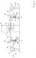
- FIG. 1 shows a rolling mill with the following details.
- a roll stand 12 is built on a foundation 11, in which two superposed ones Work rolls 13, 14 and two lying in a vertical alignment with these Back-up rolls 15, 16 can be seen.
- the belt comes from a first reel device 21, of the left-handed reel 22, the band 18 over the bottom is handled.
- the tape runs from the reel device 21 into a tape storage arrangement 23 with tape storage and tensile reinforcement function in the form of a Double roller arrangement consisting of a movable upper roller 24 and a fixed lower roller 25 there. With a horizontal double arrow 26 it is indicated that the movable roller 24 in the device 23 can be moved horizontally in a controlled manner can.
- a movement of the movable roller 24 changes in the direction indicated here Execution the length of the belt run between the movable roller 24 and the roll gap 17, and also the length of the strip run between the movable Roll 24 and the fixed roll 25.
- the lower, fixed roll 25, is by means of a rocker 27 from its operating position (25) into an insertion position (25 ') the band line 28 to pivot. With dotted lines the insertion position (25 ') the lower roller 25 indicated, in which the band 18 along the also dashed illustrated line 28 can be inserted into the roll stand 12. Only when the band 18 is fixed in the device 33 for reeling, the roller 25 swivels in their operating position (25) shown with solid lines.
- a second reel device 31 is shown for reeling, on the left-rotating one Reel 32 the rolled strip 18 is wound over the bottom.
- Tape storage and tensile reinforcement function consisting of a movable upper roll 34 and a fixed lower roller 35.
- the movable roller 35 compared to the fixed roller 34 in the Device 33 slidably controlled. This also changes the length of the Belt runs between the movable roller 34 and the fixed roller 35 as well as that Length of the belt run between the movable roller 34 and the roll gap 17.
- the above-mentioned tensile strengthening function results when at least one the rollers 24, 25 with brake means, not shown, and at least one of the rollers 34, 35 is connected to drive means, not shown, and is operated.
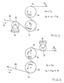
- FIG. 2 shows a rolling mill with the following details.
- a roll stand 12 is built on a foundation 11, in which two superimposed work rolls 13, 14 and two in a vertical alignment with these lying support rollers 15, 16 can be seen. Between the work rolls 13, 14 there is an adjustable or controllable roll gap 17 through which a metal strip 18 passes through from left to right.
- the tape comes from one first reel device 21, from the right-handed reel 22 of the band 18 the top is unwound.
- the tape runs from the reel device 21 into a Tape storage arrangement 23 with tape storage and tensile reinforcement function in the form a double roller assembly consisting of a fixed upper roller 24 and one movable lower roller 25 there. With a circular arrow 26 ' is indicated that the movable roller 25 in the device 23 about the axis the fixed roller 24 can pivot.
- the movable roller 25 can alternatively be adjustable in height.
- a Movement of the movable roller 25 changes in the hereby indicated Executions at least the length of the band strand between the reel 22 and the movable roller 25, in the second case (26 ") also the length of the belt run between the movable roller 25 and the fixed roller 24.
- the lower roller 25 is by means of a rocker 27 from its operating position (25) to an insertion position (25 ') to pivot over the belt line 28.
- the insertion position is with dashed lines (25 ') of the lower roller 25 indicated, in which the band 18 along the likewise Belt line 28 shown in dashed lines can be inserted into the roll stand 12. Only when the band 18 is fixed in the device 33 for reeling does the band pivot Roll 25 back into its operating position (25) shown with solid lines.
- a second reel device 31 is shown for reeling, on the right-handed one Reel 32 the rolled strip 18 is wound over the top.
- a further tape storage arrangement 33 is located on the stand 12 and the device 31 with tape storage and tensile reinforcement function, which consists of a fixed upper roll 34 and a movable lower roller 35.
- the movable roller 35 is opposite the fixed Roller 34 is pivotable about the axis of fixed roller 34, as by a vertical Double arrow 36 "indicated, the movable roller 35 can be moved up and down his.
- the above-mentioned tensile strengthening function results when at least one the rollers 24, 25 with brake means, not shown, and at least one of the rollers 34, 35 is connected to drive means, not shown, and is operated.
- FIG 3 is a tape storage device on the inlet side of the one to be assumed on the right Roll stand with an upper roller 24 and a lower roller 25 shown in the embodiment shown here, the lower roller 25 preferably the movable one Role is.
- the roll 25 On the side of the reel-off device to be assumed on the left is the roll 25 upstream of a further roller 19, over which the belt 18 is guided and deflected becomes.
- the roller 19 is supported on a fixed web via a load cell 20. When using this load cell, the roller 19 is preferably freely rotatable. However, the roller 19 can also be used to generate a controllable one Braking torque to be connected.
- a tape storage device is on the input side to the one to be assumed on the right Roll nip shown, the upper roller 24 and a lower roller 25th includes.
- the upper roller 24 is preferably controllably movable.
- a further roller 29 is arranged adjacent to the upper roller 24 and has a Load cell 30 is supported on a fixed web. The one running out of the roll 24 Band is deflected by the roller 29.
- Roll 29 is also in use here a load cell 30 preferably freely rotatable. If you do not Load cell can, however, also the role 29 with means for generating a Braking torque are connected.
- the arrangement shown can also be on the output side can be used for the roll gap, in which case the roller 29 may then be controlled Drive means can be connected.
Landscapes
- Engineering & Computer Science (AREA)
- Mechanical Engineering (AREA)
- Metal Rolling (AREA)
- Winding, Rewinding, Material Storage Devices (AREA)
- Controlling Rewinding, Feeding, Winding, Or Abnormalities Of Webs (AREA)
Abstract
Description
- Figur 1
- zeigt eine erfindungsgemäße Walzanlage als Prinzipbild in Seitenansicht in einer ersten Ausführung;
- Figur 2
- zeigt eine erfindungsgemäße Walzanlage als Prinzipbild in Seitenansicht in einer zweiten Ausführung;
- Figur 3
- zeigt Bandspeichermittel auf der Einlaufseite als Einzelheit in einer ersten Ausführung;
- Figur 4
- zeigt Bandspeichermittel auf der Einlaufseite als Einzelheit in einer zweiten Ausführung;
- 11
- Fundament
- 12
- Walzgerüst
- 13
- Arbeitswalze
- 14
- Arbeitswalze
- 15
- Stützwalze
- 16
- Stützwalze
- 17
- Walzspalt
- 18
- Band
- 19
- Rolle
- 20
- Kraftmeßdose
- 21
- Haspelvorrichtung
- 22
- Haspel
- 23
- Bandspeicheranordnung
- 24
- obere Rolle
- 25
- untere Rolle
- 26
- Doppelpfeil
- 27
- Schwinge
- 28
- Bandlinie
- 29
- Rolle
- 30
- Kraftmeßdose
- 31
- Haspelvorrichtung
- 32
- Haspel
- 33
- Bandspeicheranordnung
- 34
- obere Rolle
- 35
- untere Rolle
- 36
- Doppelpfeil
- 37
- Schwinge
Claims (26)
- Verfahren zum Warm- oder Kaltwalzen von Metallband (18), insbesondere zum flexiblen Walzen von Band mit veränderlicher Bandenddicke, mit einer ersten Haspelvorrichtung (21) zum Abhaspeln, von der Band (18) mit einer definierten Bandausgangsdicke abgewickelt wird, einem Walzgerüst (12), insbesondere einem Reversiergerüst, das zumindest zwei Arbeitswalzen (13, 14) umfaßt, zwischen denen ein in der Weite steuerbarer und/oder regelbarer Walzspalt (17) gebildet wird, einer zweiten Haspelvorrichtung (31) zum Aufhaspeln, auf die Band (18) mit einer gegenüber der definierten Bandausgangsdicke reduzierten Bandenddicke aufgewickelt wird, sowie mit ersten Bandspeichermitteln (23) aus einer Mehrzahl von Rollen zwischen der ersten Haspelvorrichtung (21) und dem Walzgerüst (12), und mit zweiten Bandspeichermitteln (33) aus einer Mehrzahl von Rollen zwischen dem Walzgerüst (12) und der zweiten Haspelvorrichtung (31), wobei die Rollen der ersten und zweiten Bandspeichermittel zur Bandspeicherung in ihrer Stellung relativ zueinander verändert werden,
dadurch gekennzeichnet, daß das Metallband (18) über zumindest eines der Bandspeichermittel (23, 33) in Form eines "S" geführt wird, wobei beim Walzen durch gesteuerte und/oder geregelte Bewegung zumindest einer der Rollen (24, 25, 34, 35) der Bandspeichermittel (23, 33) das S so verzerrt wird, daß die Länge des Metallbandes zwischen dem Einlauf und dem Auslauf in die bzw. aus den Bandspeichermitteln (23, 33) verändert wird. - Verfahren nach Anspruch 1,
dadurch gekennzeichnet, daß das Metallband (18) über die Bandspeichermittel (23, 33) in Form eines stehenden S, mit zumindest teilweise in verschiedener Höhe liegenden Bögen, insbesondere mit sich in vertikaler Projektion zumindest teilweise überdeckenden Bögen geführt wird. - Verfahren nach Anspruch 2,
dadurch gekennzeichnet, daß die Zentren der übereinanderliegenden Bögen des S bei der Bewegung der Rollen zumindest zeitweise vertikal übereinanderliegen. - Verfahren nach einem der Ansprüche 1 bis 3,
dadurch gekennzeichnet, daß der obere Bogen des "S" in seiner Lage verändert wird, insbesondere bei einer vom Walzspalt (17) herrührenden Geschwindigkeitsstörung. - Verfahren nach einem der Ansprüche 1 bis 3,
dadurch gekennzeichnet, daß der untere Bogen des "S" in seiner Lage verändert wird, insbesondere bei einer von den Haspelvorrichtungen (22, 32) herrührenden Geschwindigkeitsstörung. - Verfahren zum Warm- oder Kaltwalzen von Metallband (18), insbesondere zum flexiblen Walzen von Band mit veränderlicher Bandenddicke, mit einer ersten Haspelvorrichtung (21) zum Abhaspeln, von der Band (18) mit einer definierten Bandausgangsdicke abgewickelt wird, einem Walzgerüst (12), insbesondere einem Reversiergerüst, das zumindest zwei Arbeitswalzen (13, 14) umfaßt, zwischen denen ein in der Weite steuerbarer und/oder regelbarer Walzspalt (17) gebildet wird, einer zweiten Haspelvorrichtung (31) zum Aufhaspeln, auf die Band (18) mit einer gegenüber der definierten Bandausgangsdicke reduzierten Bandenddicke aufgewickelt wird, sowie mit ersten Bandspeichermitteln (23) aus einer Mehrzahl von Rollen zwischen der ersten Haspelvorrichtung (21) und dem Walzgerüst (12), und mit zweiten Bandspeichermitteln (33) aus einer Mehrzahl von Rollen zwischen dem Walzgerüst (12) und der zweiten Haspelvorrichtung (31), wobei die Rollen der ersten und zweiten Bandspeichermittel zur Bandspeicherung in ihrer Stellung relativ zueinander verändert werden, insbesondere nach einem der Ansprüche 1 bis 5,
dadurch gekennzeichnet, daß zumindest eine Rolle (24, 25) der ersten Bandspeichermittel (23) zur Verstärkung des Bandzugs am Walzspalt (17) mit steuerbarem und/oder regelbarem Bremsmoment abgebremst wird und zumindest eine Rolle (34, 35) der zweiten Bandspeichermittel (33) zur Verstärkung des Bandzugs am Walzspalt (17) mit steuerbarem und/oder regelbarem Antriebsmoment angetrieben wird. - Verfahren nach Anspruch 6,
dadurch gekennzeichnet, daß das Bremsmoment der Rolle der ersten Bandspeichermittel (23) und das Antriebsmoment der Rolle der zweiten Bandspeichermittel (33) beim Walzen von Band (18) mit veränderlicher Banddicke auf konstanten Bandzug geregelt wird. - Verfahren nach einem der Ansprüche 6 oder 7,
dadurch gekennzeichnet, daß die Steuerung und/oder Regelung des Bandzugs durch Veränderung des Bremsmomentes an mehreren Rollen der ersten Bandspeichermittel (23) und/oder durch Veränderung des Antriebsmomentes an mehreren Rollen der zweiten Bandspeichermittel (33) erfolgt. - Verfahren nach einem der Ansprüche 6 bis 8,
dadurch gekennzeichnet, daß die Steuerung und/oder Regelung des Bandzugs zusätzlich durch Änderung der relativen Rollenpositionen der Rollen der ersten Bandspeichermittel (23) und/oder der relativen Rollenpositionen der Rollen der zweiten Bandspeichermittel (33) erfolgt. - Walzanlage zum Warm- oder Kaltwalzen von Metallband (18), insbesondere zum flexiblen Walzen von Band mit veränderlicher Bandenddicke, mit einer ersten Haspelvorrichtung (21) zum Abhaspeln, von der Band (18) mit definierter Bandausgangsdicke abwickelbar ist, einem Walzgerüst (12), insbesondere einem Reversiergerüst, das zumindest zwei Arbeitswalzen (13, 14) umfaßt, zwischen denen ein in der Weite steuerbarer und/oder regelbarer Walzspalt (17) gebildet wird,
einer zweiten Haspelvorrichtung (31) zum Aufhaspeln, auf die Band (18) mit einer gegenüber der definierten Bandausgangsdicke reduzierten Bandenddicke aufwickelbar ist, sowie mit ersten Bandspeichermitteln (23) aus einer Mehrzahl von Rollen zwischen der ersten Haspelvorrichtung (21) und dem Walzgerüst (12) und mit zweiten Bandspeichermitteln (33) aus einer Mehrzahl von Rollen zwischen dem Walzgerüst (12) und der zweiten Haspelvorrichtung (31),
dadurch gekennzeichnet, daß zumindest eines der Bandspeichermittel (23, 33) aus einer Doppelrollenanordnung mit S-förmiger Bandumschlingung von zwei Rollen (24, 25; 34, 35) gebildet wird, deren Achsen in der Höhe unterschiedlich angeordnet sind, wobei eine erste Rolle (24, 34) das Band (18) zwischen der Doppelrollenanordnung (23, 33) und dem Walzgerüst (12) spannt und eine zweite Rolle (25, 35) das Band (18) zwischen der Doppelrollenanordnung (23, 33) und der entsprechenden Haspelvorrichtung (21, 31) spannt und durch eine Bewegung zumindest einer beweglichen Rolle (24, 34; 25, 35) die Länge des Bandtrums zwischen Haspelvorrichtung (21, 31) und zweiter Rolle (25, 35) und/oder zwischen zweiter Rolle (25, 35) und erster Rolle (24, 34) beim Walzen veränderbar ist. - Walzanlage nach Anspruch 10,
dadurch gekennzeichnet, daß die Rollen der Bandspeichermittel (23, 33) sich in vertikaler Projektion zumindest teilweise überdecken. - Walzanlage nach Anspruch 11,
dadurch gekennzeichnet, daß die Achsen der Rollen der Bandspeichermittel (23, 33) bei ihrer Bewegung zumindest zeitweise vertikal übereinanderliegen. - Walzanlage nach einem der Ansprüche 10 bis 12,
dadurch gekennzeichnet, daß eine bewegliche Rolle (24, 35) über einer weiteren Rolle (25, 35) angeordnet ist und daß das Bandmaterial in den ersten Bandspeichermitteln (23) über die weitere Rolle (25) einläuft und über die bewegliche Rolle (24) ausläuft, und in den zweiten Bandspeichermitteln (33) über die bewegliche Rolle (34) einläuft und über die weitere Rolle (35) ausläuft. - Walzanlage nach einem der Ansprüche 10 bis 12,
dadurch gekennzeichnet, daß eine bewegliche Rolle (25, 35) unter einer weiteren Rolle (24, 34) angeordnet ist und daß das Bandmaterial in den ersten Bandspeichermitteln (23) über die bewegliche Rolle (25) einläuft und über die weitere Rolle (24) ausläuft und in den zweiten Bandspeichermitteln (33) über die weitere Rolle (34) einläuft und über die bewegliche Rolle (35) ausläuft. - Walzanlage nach einem der Ansprüche 10 bis 14,
dadurch gekennzeichnet, daß die bewegliche Rolle (24, 34; 25, 35) im Betrieb senkrecht zur Bandlinie (pass-line) (28) beweglich ist. - Walzanlage nach einem der Ansprüche 10 bis 14,
dadurch gekennzeichnet, daß die bewegliche Rolle (24, 34; 25, 35) im Betrieb parallel zur Bandlinie (pass-line) (28) beweglich ist. - Walzanlage nach einem der Ansprüche 10 bis 14,
dadurch gekennzeichnet, daß die bewegliche Rolle (24, 34; 25, 35) um eine Drehachse pendelnd angeordnet ist, die außerhalb ihres Rollenquerschnitts, insbesondere auf der Drehachse der weiteren Rolle (25, 35; 24, 34) liegt. - Walzanlage nach einem der Ansprüche 10 bis 17,
dadurch gekennzeichnet, daß eine untere Rolle (25, 35) zum Einführen eines Bandanfangs von der ersten Haspelvorrichtung (21) in den Walzspalt (17) und aus dem Walzspalt (17) auf die zweite Haspelvorrichtung (31) aus ihrer Betriebsposition (25, 35) auf die entgegengesetzte Seite der Bandlinie (pass-line) (28) in eine Einführposition (25', 35') schwenkbar ist. - Walzanlage nach einem der Ansprüche 10 bis 18,
dadurch gekennzeichnet, daß das Band (18) von der Unterseite der ersten Haspelvorrichtung (21) abläuft. - Walzanlage nach einem der Ansprüche 10 bis 19,
dadurch gekennzeichnet, daß das Band (18) auf der Unterseite der zweiten Haspelvorrichtung (31) einläuft. - Walzanlage zum Warm- oder Kaltwalzen von Metallband (18), insbesondere zum flexiblen Walzen von Band mit veränderlicher Bandenddicke, mit einer ersten Haspelvorrichtung (21) zum Abhaspeln, von der Band (18) mit einer definierten Bandausgangsdicke abwickelbar ist, einem Walzgerüst (12), insbesondere einem Reversiergerüst, das zumindest zwei Arbeitswalzen (13, 14) umfaßt, zwischen denen ein in der Weite steuerbarer und/oder regelbarer Walzspalt (17) gebildet wird,
einer zweiten Haspelvorrichtung (31) zum Aufhaspeln, auf die Band (18) mit einer gegenüber der definierten Bandausgangsdicke reduzierten Bandenddicke aufwickelbar ist, sowie mit ersten Bandspeichermitteln (23) aus einer Mehrzahl von Rollen zwischen der ersten Haspelvorrichtung (21) und dem Walzgerüst (12) und mit zweiten Bandspeichermitteln aus einer Mehrzahl von Rollen zwischen dem Walzgerüst (12) und der zweiten Haspelvorrichtung (31), insbesondere nach einem der Ansprüche 10 bis 20,
dadurch gekennzeichnet, daß zumindest eine Rolle der ersten Bandspeichermittel (23) mit Mitteln zur Erzeugung von gesteuert und/oder geregelt veränderbaren Bremsmomenten verbunden ist und zumindest eine Rolle der zweiten Bandspeichermittel (33) mit Mitteln zur Erzeugung von gesteuert und/oder geregelt veränderbaren Antriebsmomenten verbunden ist. - Walzanlage nach Anspruch 21,
dadurch gekennzeichnet, daß die Mittel zur Erzeugung der Bremsmomente und/oder die Mittel zu Erzeugung der Antriebsmomente durch elektrische Maschinen (Generatoren/E-Motoren) gebildet werden. - Walzanlage nach Anspruch 21,
dadurch gekennzeichnet, daß die Mittel zur Erzeugung der Bremsmomente und/oder die Mittel zur Erzeugen der Antriebsmomente durch hydrostatische Maschinen (Hydropumpen/Hydromotoren) gebildet werden. - Walzanlage nach einem der Ansprüche 21 bis 23,
dadurch gekennzeichnet, daß den Bandspeichermitteln (23, 33) weitere frei drehende Rollen (19, 29) unmittelbar vor- oder nachgeordnet sind. - Walzanlage nach einem der Ansprüche 21 bis 24,
dadurch gekennzeichnet, daß den Bandspeichermitteln (23, 33) weitere abbremsbare bzw. antreibbare Rollen (19, 29) unmittelbar vor- oder nachgeordnet sind. - Walzanlage nach einem der Ansprüche 21 bis 25,
dadurch gekennzeichnet, daß weitere Rollen (19, 29) zur Messung des Bandzuges über Kraftmeßdosen (20, 30) an festen Stegen abgestützt sind.
Applications Claiming Priority (2)
| Application Number | Priority Date | Filing Date | Title |
|---|---|---|---|
| DE10315357 | 2003-04-03 | ||
| DE10315357A DE10315357B4 (de) | 2003-04-03 | 2003-04-03 | Verfahren zum Walzen und Walzanlage zum Walzen von Metallband |
Publications (2)
| Publication Number | Publication Date |
|---|---|
| EP1464415A2 true EP1464415A2 (de) | 2004-10-06 |
| EP1464415A3 EP1464415A3 (de) | 2006-08-16 |
Family
ID=32842250
Family Applications (1)
| Application Number | Title | Priority Date | Filing Date |
|---|---|---|---|
| EP04007926A Withdrawn EP1464415A3 (de) | 2003-04-03 | 2004-04-01 | Verfahren zum Walzen und Walzanlage zum Walzen von Metallband |
Country Status (4)
| Country | Link |
|---|---|
| US (1) | US7185523B2 (de) |
| EP (1) | EP1464415A3 (de) |
| JP (1) | JP2004344974A (de) |
| DE (1) | DE10315357B4 (de) |
Cited By (6)
| Publication number | Priority date | Publication date | Assignee | Title |
|---|---|---|---|---|
| WO2006021324A1 (de) * | 2004-08-26 | 2006-03-02 | Sms Demag Ag | Walzwerk zum walzen von metallischem band |
| WO2006119998A1 (en) * | 2005-05-11 | 2006-11-16 | Corus Staal Bv | Method and apparatus for producing strip having a variable thickness |
| DE102006024939A1 (de) * | 2006-05-29 | 2007-12-06 | Siemens Ag | Spannrollensatz mit mindestens zwei Spannrollen |
| EP1908534A1 (de) * | 2006-10-07 | 2008-04-09 | ACHENBACH BUSCHHÜTTEN GmbH | Walzwerk und Verfahren zum flexiblen Kalt- oder Warm-Einweg- oder Reversierwalzen von Metallband |
| WO2012084638A1 (de) * | 2010-12-22 | 2012-06-28 | Sms Siemag Ag | Vorrichtung und verfahren zum walzen eines metallbandes |
| CN103537487A (zh) * | 2013-10-31 | 2014-01-29 | 中冶南方工程技术有限公司 | 一种多机架轧机的末两个机架间张力的控制方法 |
Families Citing this family (16)
| Publication number | Priority date | Publication date | Assignee | Title |
|---|---|---|---|---|
| BRPI0807565B1 (pt) | 2007-02-23 | 2017-06-13 | Corus Staal Bv | Method of termomechanical formating of a final product with very high resistance and a product produced through the same |
| CN101802230B (zh) * | 2007-07-19 | 2012-10-17 | 塔塔钢铁艾默伊登有限责任公司 | 在长度方向上具有可变厚度的钢带 |
| US8864921B2 (en) * | 2007-07-19 | 2014-10-21 | Tata Steel Ijmuiden B.V. | Method for annealing a strip of steel having a variable thickness in length direction |
| EP2025771A1 (de) * | 2007-08-15 | 2009-02-18 | Corus Staal BV | Verfahren zur Herstellung eines beschichteten Stahlbandes zur Herstellung von Platinenzuschnitten zur thermomechanischen Formgebung, so hergestelltes Band und Verwendung eines solchen Bandes |
| CN102320000B (zh) * | 2011-07-08 | 2013-01-30 | 邢台纳科诺尔极片轧制设备有限公司 | 一种电池极片碾压分切系统 |
| CN103717322B (zh) * | 2011-08-08 | 2016-09-28 | 首要金属科技奥地利有限责任公司 | 轧制设备以及用于轧制的方法 |
| CN105772512B (zh) * | 2014-12-23 | 2018-04-27 | 宝山钢铁股份有限公司 | 变厚度板成卷轧制时张力稳定方法 |
| SI3097992T1 (sl) * | 2015-05-29 | 2017-10-30 | Giebel Kaltwalzwerk Gmbh | Postopek za stopenjsko valjanje kovinskega traku |
| CN105499699A (zh) * | 2016-01-21 | 2016-04-20 | 山东裴森动力新能源有限公司 | 一种自动控制式锂电池极片裁切机构 |
| ES2945411T3 (es) * | 2018-08-15 | 2023-07-03 | Muhr & Bender Kg | Dispositivo, instalación de laminación y procedimiento para la regulación de una tensión frontal durante el laminado flexible de una banda metálica |
| DE102019215265A1 (de) | 2018-12-06 | 2020-06-10 | Sms Group Gmbh | Verfahren zum Betreiben eines Walzgerüstes zum Stufenwalzen |
| DE102019132133A1 (de) | 2019-11-27 | 2021-05-27 | Muhr Und Bender Kg | Anlage und verfahren zum flexiblen walzen von metallischem bandmaterial |
| CN112157557A (zh) * | 2020-10-27 | 2021-01-01 | 湖南立方新能源科技有限责任公司 | 一种金属锂带表面处理装置、表面处理方法、锂金属电池 |
| CN117000759B (zh) * | 2023-10-07 | 2023-12-08 | 福建紫金英菲迅应用材料有限公司 | 一种金锡合金制品生产设备及其使用方法 |
| CN117696646A (zh) * | 2024-01-03 | 2024-03-15 | 中冶京诚工程技术有限公司 | 平整机入出口立式张力辊、平整机机组及穿带方法 |
| CN119588784A (zh) * | 2025-01-09 | 2025-03-11 | 北京京诚之星科技开发有限公司 | 平整机组及其工作方法 |
Family Cites Families (11)
| Publication number | Priority date | Publication date | Assignee | Title |
|---|---|---|---|---|
| DE100532C (de) | ||||
| US2647743A (en) * | 1949-06-29 | 1953-08-04 | Eastern Metals Res Co Inc | Spring device |
| US3709017A (en) * | 1969-06-26 | 1973-01-09 | V Vydrin | Method of rolling metal sheet articles between the driven rolls of the roll mill |
| GB1545114A (en) * | 1977-05-16 | 1979-05-02 | Head Wrightson & Co Ltd | Method and apparatus for producing strip material |
| DE3024682A1 (de) * | 1980-06-30 | 1982-01-28 | Schloemann-Siemag AG, 4000 Düsseldorf | Dressiergeruest mit vom walzband in s-form umschlungenen zugwalzen |
| JPS6289512A (ja) * | 1985-10-14 | 1987-04-24 | Kawasaki Steel Corp | 冷間圧延機の出側設備 |
| JP2792227B2 (ja) * | 1990-11-14 | 1998-09-03 | 石川島播磨重工業株式会社 | 圧延装置 |
| JP2794934B2 (ja) * | 1990-11-15 | 1998-09-10 | 石川島播磨重工業株式会社 | 圧延機の板厚制御装置 |
| DE10004532A1 (de) * | 2000-02-02 | 2001-08-30 | Josef Froehling Gmbh Walzwerks | Vorrichtung zum Walzen von Bändern mit periodisch veränderlicher Bandenddicke |
| DE10133756A1 (de) * | 2001-07-11 | 2003-01-30 | Sms Demag Ag | Kaltwalzwerk sowie Verfahren zum Kaltwalzen von metallischem Band |
| DE10310399B4 (de) * | 2003-03-07 | 2005-03-03 | Sundwig Gmbh | Vorrichtung und Verfahren zum Walzen von Metallbändern |
-
2003
- 2003-04-03 DE DE10315357A patent/DE10315357B4/de not_active Expired - Fee Related
-
2004
- 2004-04-01 JP JP2004109013A patent/JP2004344974A/ja active Pending
- 2004-04-01 EP EP04007926A patent/EP1464415A3/de not_active Withdrawn
- 2004-04-02 US US10/817,084 patent/US7185523B2/en not_active Expired - Fee Related
Cited By (9)
| Publication number | Priority date | Publication date | Assignee | Title |
|---|---|---|---|---|
| WO2006021324A1 (de) * | 2004-08-26 | 2006-03-02 | Sms Demag Ag | Walzwerk zum walzen von metallischem band |
| WO2006119998A1 (en) * | 2005-05-11 | 2006-11-16 | Corus Staal Bv | Method and apparatus for producing strip having a variable thickness |
| DE102006024939A1 (de) * | 2006-05-29 | 2007-12-06 | Siemens Ag | Spannrollensatz mit mindestens zwei Spannrollen |
| DE102006024939B4 (de) * | 2006-05-29 | 2008-05-29 | Siemens Ag | Spannrollensatz mit mindestens zwei Spannrollen, Walzstraße mit mehreren Walzgerüsten und mindestens einem Spannrollensatz und Verfahren zur Beeinflussung der Zugspannung in einem Metallband mit Hilfe von zwei Spannrollen |
| EP1908534A1 (de) * | 2006-10-07 | 2008-04-09 | ACHENBACH BUSCHHÜTTEN GmbH | Walzwerk und Verfahren zum flexiblen Kalt- oder Warm-Einweg- oder Reversierwalzen von Metallband |
| DE102006047463A1 (de) * | 2006-10-07 | 2008-04-17 | ACHENBACH BUSCHHüTTEN GMBH | Walzwerk und Verfahren zum flexiblen Kalt- oder Warm- Einweg- oder Reversierwalzen von Metallband |
| WO2012084638A1 (de) * | 2010-12-22 | 2012-06-28 | Sms Siemag Ag | Vorrichtung und verfahren zum walzen eines metallbandes |
| CN103537487A (zh) * | 2013-10-31 | 2014-01-29 | 中冶南方工程技术有限公司 | 一种多机架轧机的末两个机架间张力的控制方法 |
| CN103537487B (zh) * | 2013-10-31 | 2016-04-20 | 中冶南方工程技术有限公司 | 一种多机架轧机的末两个机架间张力的控制方法 |
Also Published As
| Publication number | Publication date |
|---|---|
| US7185523B2 (en) | 2007-03-06 |
| EP1464415A3 (de) | 2006-08-16 |
| DE10315357B4 (de) | 2005-05-25 |
| US20040255633A1 (en) | 2004-12-23 |
| DE10315357A1 (de) | 2004-11-04 |
| JP2004344974A (ja) | 2004-12-09 |
Similar Documents
| Publication | Publication Date | Title |
|---|---|---|
| DE10315357B4 (de) | Verfahren zum Walzen und Walzanlage zum Walzen von Metallband | |
| EP1406735B1 (de) | Kaltwalzerk sowie verfahren zum kaltwalzen von metallischem band | |
| DE2519988A1 (de) | Verfahren und vorrichtung zum auf- und abwickeln von warmgewalzten vorbaendern aus heissem metall | |
| EP3210681B1 (de) | Vorrichtung und verfahren zum walzen von bandmaterial mit veränderlicher banddicke | |
| EP2838676A1 (de) | Verfahren und vorrichtung zum zunderbrechen eines zunderbehafteten metallbandes | |
| EP1446242B1 (de) | Verfahren und vorrichtung zur kontinuierlichen herstellung eines gewalzten metallbandes aus einer metallschmelze | |
| DE69909332T2 (de) | Integriertes kontinuierliches stranggiess- und inline warmwalzverfahren sowie entsprechendes verfahren mit zwischenwickeln und abwickeln des vorstreifens | |
| WO1989008512A1 (fr) | Installation pour la fabrication de rubans d'acier lamines a chaud | |
| DE69302332T2 (de) | Vorrichtung zum Auf- und Abwinkeln von dünnen Brammen | |
| EP1784266B1 (de) | Walzwerk zum walzen von metallischem band | |
| DE10310399B4 (de) | Vorrichtung und Verfahren zum Walzen von Metallbändern | |
| DE60004948T2 (de) | Verfahren zur kontinuierlichen herstellung eines metallbandes | |
| EP3691803B1 (de) | Multiflexible walzanlage | |
| DE102006047463A1 (de) | Walzwerk und Verfahren zum flexiblen Kalt- oder Warm- Einweg- oder Reversierwalzen von Metallband | |
| DE102010063827A1 (de) | Vorrichtung und Verfahren zum Walzen eines Metallbandes | |
| DE2613459A1 (de) | Verfahren und anlage zur vermeidung des schrottanfalles in kontinuierlichen breitbandstrassen | |
| DE19821301A1 (de) | Anordnung und Verfahren zum Erzeugen von Stahlband | |
| DE3024682A1 (de) | Dressiergeruest mit vom walzband in s-form umschlungenen zugwalzen | |
| EP3873685B1 (de) | Walzlinie | |
| AT407613B (de) | Vorrichtung zum endloswickeln von bandmaterial | |
| EP4717371A1 (de) | Verfahren und reversierwalzwerk zum walzen eines metallischen bandes | |
| LU85977A1 (de) | Verfahren und vorrichtung zum zurichten von warmband-coils,insbesondere coilbox-coils | |
| WO1998034754A1 (de) | Induktionsschweisseinrichtung und arbeitsverfahren zum verbinden mehrerer vorbänder in einer anlage zur endlosherstellung von warmgewalztem stahlband | |
| AT514371B1 (de) | Verfahren und Vorrichtung zum Aufrollen von Faserbahnen, insbesondere von Papier- und Kartonbahnen | |
| AT265825B (de) | Einrichtung zur kontinuierlichen Herstellung von geschweißten Stahlrohren kleiner Abmessungen |
Legal Events
| Date | Code | Title | Description |
|---|---|---|---|
| PUAI | Public reference made under article 153(3) epc to a published international application that has entered the european phase |
Free format text: ORIGINAL CODE: 0009012 |
|
| AK | Designated contracting states |
Kind code of ref document: A2 Designated state(s): AT BE BG CH CY CZ DE DK EE ES FI FR GB GR HU IE IT LI LU MC NL PL PT RO SE SI SK TR |
|
| AX | Request for extension of the european patent |
Extension state: AL HR LT LV MK |
|
| PUAL | Search report despatched |
Free format text: ORIGINAL CODE: 0009013 |
|
| AK | Designated contracting states |
Kind code of ref document: A3 Designated state(s): AT BE BG CH CY CZ DE DK EE ES FI FR GB GR HU IE IT LI LU MC NL PL PT RO SE SI SK TR |
|
| AX | Request for extension of the european patent |
Extension state: AL HR LT LV MK |
|
| 17P | Request for examination filed |
Effective date: 20060915 |
|
| AKX | Designation fees paid |
Designated state(s): AT BE BG CH CY CZ DE DK EE ES FI FR GB GR HU IE IT LI LU MC NL PL PT RO SE SI SK TR |
|
| RIN1 | Information on inventor provided before grant (corrected) |
Inventor name: HAUGER, ANDREAS, DR. ING. |
|
| STAA | Information on the status of an ep patent application or granted ep patent |
Free format text: STATUS: THE APPLICATION HAS BEEN WITHDRAWN |
|
| 18W | Application withdrawn |
Effective date: 20080404 |