EP1464415A2 - Method and installation for rolling metal strip - Google Patents
Method and installation for rolling metal strip Download PDFInfo
- Publication number
- EP1464415A2 EP1464415A2 EP04007926A EP04007926A EP1464415A2 EP 1464415 A2 EP1464415 A2 EP 1464415A2 EP 04007926 A EP04007926 A EP 04007926A EP 04007926 A EP04007926 A EP 04007926A EP 1464415 A2 EP1464415 A2 EP 1464415A2
- Authority
- EP
- European Patent Office
- Prior art keywords
- strip
- storage means
- roller
- roll
- rolling
- Prior art date
- Legal status (The legal status is an assumption and is not a legal conclusion. Google has not performed a legal analysis and makes no representation as to the accuracy of the status listed.)
- Withdrawn
Links
Images

Classifications
-
- B—PERFORMING OPERATIONS; TRANSPORTING
- B21—MECHANICAL METAL-WORKING WITHOUT ESSENTIALLY REMOVING MATERIAL; PUNCHING METAL
- B21B—ROLLING OF METAL
- B21B37/00—Control devices or methods specially adapted for metal-rolling mills or the work produced thereby
- B21B37/16—Control of thickness, width, diameter or other transverse dimensions
- B21B37/24—Automatic variation of thickness according to a predetermined programme
-
- B—PERFORMING OPERATIONS; TRANSPORTING
- B21—MECHANICAL METAL-WORKING WITHOUT ESSENTIALLY REMOVING MATERIAL; PUNCHING METAL
- B21B—ROLLING OF METAL
- B21B37/00—Control devices or methods specially adapted for metal-rolling mills or the work produced thereby
- B21B37/48—Tension control; Compression control
-
- B—PERFORMING OPERATIONS; TRANSPORTING
- B21—MECHANICAL METAL-WORKING WITHOUT ESSENTIALLY REMOVING MATERIAL; PUNCHING METAL
- B21B—ROLLING OF METAL
- B21B39/00—Arrangements for moving, supporting, or positioning work, or controlling its movement, combined with or arranged in, or specially adapted for use in connection with, metal-rolling mills
- B21B39/02—Feeding or supporting work; Braking or tensioning arrangements, e.g. threading arrangements
- B21B39/08—Braking or tensioning arrangements
-
- B—PERFORMING OPERATIONS; TRANSPORTING
- B21—MECHANICAL METAL-WORKING WITHOUT ESSENTIALLY REMOVING MATERIAL; PUNCHING METAL
- B21B—ROLLING OF METAL
- B21B41/00—Guiding, conveying, or accumulating easily-flexible work, e.g. wire, sheet metal bands, in loops or curves; Loop lifters
- B21B41/08—Guiding, conveying, or accumulating easily-flexible work, e.g. wire, sheet metal bands, in loops or curves; Loop lifters without overall change in the general direction of movement of the work
-
- B—PERFORMING OPERATIONS; TRANSPORTING
- B21—MECHANICAL METAL-WORKING WITHOUT ESSENTIALLY REMOVING MATERIAL; PUNCHING METAL
- B21B—ROLLING OF METAL
- B21B1/00—Metal-rolling methods or mills for making semi-finished products of solid or profiled cross-section; Sequence of operations in milling trains; Layout of rolling-mill plant, e.g. grouping of stands; Succession of passes or of sectional pass alternations
- B21B1/22—Metal-rolling methods or mills for making semi-finished products of solid or profiled cross-section; Sequence of operations in milling trains; Layout of rolling-mill plant, e.g. grouping of stands; Succession of passes or of sectional pass alternations for rolling plates, strips, bands or sheets of indefinite length
- B21B1/30—Metal-rolling methods or mills for making semi-finished products of solid or profiled cross-section; Sequence of operations in milling trains; Layout of rolling-mill plant, e.g. grouping of stands; Succession of passes or of sectional pass alternations for rolling plates, strips, bands or sheets of indefinite length in a non-continuous process
- B21B1/32—Metal-rolling methods or mills for making semi-finished products of solid or profiled cross-section; Sequence of operations in milling trains; Layout of rolling-mill plant, e.g. grouping of stands; Succession of passes or of sectional pass alternations for rolling plates, strips, bands or sheets of indefinite length in a non-continuous process in reversing single stand mills, e.g. with intermediate storage reels for accumulating work
-
- B—PERFORMING OPERATIONS; TRANSPORTING
- B21—MECHANICAL METAL-WORKING WITHOUT ESSENTIALLY REMOVING MATERIAL; PUNCHING METAL
- B21B—ROLLING OF METAL
- B21B15/00—Arrangements for performing additional metal-working operations specially combined with or arranged in, or specially adapted for use in connection with, metal-rolling mills
- B21B2015/0057—Coiling the rolled product
-
- B—PERFORMING OPERATIONS; TRANSPORTING
- B21—MECHANICAL METAL-WORKING WITHOUT ESSENTIALLY REMOVING MATERIAL; PUNCHING METAL
- B21B—ROLLING OF METAL
- B21B15/00—Arrangements for performing additional metal-working operations specially combined with or arranged in, or specially adapted for use in connection with, metal-rolling mills
- B21B2015/0064—Uncoiling the rolled product
-
- B—PERFORMING OPERATIONS; TRANSPORTING
- B21—MECHANICAL METAL-WORKING WITHOUT ESSENTIALLY REMOVING MATERIAL; PUNCHING METAL
- B21B—ROLLING OF METAL
- B21B38/00—Methods or devices for measuring, detecting or monitoring specially adapted for metal-rolling mills, e.g. position detection, inspection of the product
- B21B38/06—Methods or devices for measuring, detecting or monitoring specially adapted for metal-rolling mills, e.g. position detection, inspection of the product for measuring tension or compression
Definitions
- the invention relates to a method for hot or cold rolling metal strip, in particular for flexible rolling of strips with variable strip thickness, with one first reel device for uncoiling, from the band with a defined Strip outlet thickness is unwound, a roll stand, in particular a reversing stand, which comprises at least two work rolls, between which one in the Wide controllable and / or adjustable roll gap is formed, a second reel device for reeling, on the tape with one opposite the defined one Strip output thickness is reduced to the final strip thickness, as well as with the first Tape storage means from a plurality of rolls between the first reel device and the roll stand and with second strip storage means from a plurality of rollers between the roll stand and the second reel device, wherein the roles of the first and second tape storage means for tape storage in operation be changed in their position relative to each other; the invention further relates to a rolling mill or a rolling plant for hot or cold rolling of metal strip, especially for rolling strip with variable strip thickness, with a first reel device for uncoiling, from the band with a
- pre-rolled strip is reduced to a reduced one Rolled final thickness, which can be controlled with small tolerances in width and / or adjustable roll gap can be set and maintained.
- the Pre-rolled strip can already be flexibly rolled strip with variable Tape exit thickness.
- the so-called flexible rolling means that metal strips change periodically defined different thicknesses.
- the rolled longitudinal thickness profile corresponds in length and thickness, for example, to the later load case Sheet metal component.
- the rolling process is to be designed as cold or hot strip rolling.
- the Strip material to be rolled is unwound from a coil, rolled and then rewound under train.
- the corresponding rolling mills can reverse plants be d. H. after passing through a coil from the first to the second Reel device can be a next coil from the second to the first reel device be run through. From this tape material, according to the corresponding Post-treatment of blanks used for the manufacture of components with different wall thicknesses can be used.
- As a processing process can do any sheet metal forming process depending on the required geometry are used, e.g. B. deep drawing, stretch drawing, hydroforming, High-pressure metal forming.
- WO 03/008122 A1 or DE 100 04 532 A1 are also cold rolling mills become known with which hot strip with a substantially constant strip exit thickness with larger tolerances on periodically changing tape end thicknesses can be cold rolled within narrow tolerances.
- the Band thickness usually varies periodically between two different values set.
- the first strip storage means are in rolling mills of the type mentioned between the decoiler and the roll stand and second Strip storage means between the roll stand and the reel-up required.
- These devices in the form of dancers essentially serve maintain an approximately constant tensile load at the roll gap.
- one of the pull rollers is one after the other can be swiveled around on the opposite side and after it has entered its working position recyclable.
- the drives of the swiveling pull rollers are stationary, so that these pull rollers must be locked in place during operation.
- a function as Tape storage means is not provided by these pull rollers.
- the object of the present invention is a method for rolling and to provide a rolling system of the type mentioned, by the tape storage means with a short length along the belt line are possible.
- a further task is a process for rolling and a rolling mill to provide the type mentioned, in which the tape storage means for construction high belt tension are suitable.
- the solution to this lies in a process which is characterized in that the metal strip with at least one of the tape storage means in the form of an "S" sheets are at least partially superimposed, during the rolling by forced movement of at least one of the rolls of the tape storage means the "S" is distorted so that the length of the metal strip between the Inlet and outlet in or out of the tape storage means is changed.
- the metal strip over the tape storage means in the form of a standing "S" with at least partially lying at different heights Arches, especially with two in the horizontal direction, d. H. in vertical Projection, at least partially overlapping arches is performed.
- Another The overall length can be shortened if the centers of the superimposed ones Arches of the "S" at least temporarily vertically congruent when the rollers move superimposed.
- the definition of an "S” includes an “S” mirrored on a vertical plane.
- the “S” has two arcs (circular arcs) of opposite curvature, which are connected by a tangential line.
- the upper Bow of the "S” is controlled in its position and / or regulated changed, especially when speed disturbances of the strip speed originate from the roll gap. This is the case when using flexible rolling with variable strip thickness comes.
- the lower bow of the "S” changed its position regulated and / or controlled , in particular in the case of speed disturbances originating from the reel device.
- Such a speed disturbance can be caused by the so-called Covenant caused, d. H. the step change in diameter on the coil radially above the inside band start of the band material.
- a rolling mill according to the invention is characterized in that at least one the tape storage means from a double roller arrangement with S-shaped belt wrap is formed by two roles, the axes of which differ in height are arranged, with a first roller the belt between the double roller arrangement and the roll stand on the belt line (pass-line) and a second roll the belt between the double roller assembly and the corresponding reel device spans, and being by a movement of at least one movable the the length of the belt run between the reel and the movable reel for both reels and / or between the movable role and the other of the two roles in Rolling is changeable.
- the movable roller can be perpendicular to the operation
- Belt line (pass-line) can be movable or movable parallel to the belt line (pass-line) be or be arranged to oscillate about an axis of rotation that is outside the roller cross section, lies in particular on the axis of rotation of the further roller.
- a movable roller can be placed over another Roll be arranged, especially if there is a disturbance of the belt speed starts from the roll gap, i.e. in flexible rolling as mentioned above.
- a movable roller can be placed under another Roll be arranged, namely especially if a disturbance of the belt speed starts from the reel device by means of the collar.
- runs in the first tape storage means the tape on the movable roller and on the further role
- the second tape storage means the tape on the another role and runs out on the movable role.
- the respective lower roll can be used to insert a beginning of the tape from the uncoiler into the roll gap and from there onto the uncoiler from one Operating position in an insertion position on the opposite side of the belt line, thus be designed to be pivotable above the belt line.
- each lower roller are pivoted back into their operating position, which then Band S-shaped around the swiveling lower roller and the essentially stationary upper roller is pulled.
- Unwinding from the uncoiler as well the winding onto the reel-up device can preferably be carried out via the underside of the appropriate reels. This enables an operator to simultaneously visual tape control on both sides of the tape. Unwinding and rewinding can also done over the top of the reels, e.g. B. by the wrap angle to influence the tape storage means favorably.
- a preferred embodiment consists in a method of the aforementioned Type, which is characterized in that at least one role of the first tape storage means for tensile reinforcement at the roll gap with controllable and / or adjustable variable braking torque is braked and at least one role of the second Strip storage means for tensile reinforcement at the roll gap can be controlled and / or regulated variable drive torque is driven.
- the strip tension at the roll gap can be increased significantly while the braking or driving torques on the reels used in state-of-the-art rolling mills crucial for the development of the tape tensile forces can be significantly reduced can. In absolute terms, this is a strip tension reinforcement at the roll gap possible.
- the braking torque the aforementioned role of the first tape storage means and the drive torque the aforementioned role of the second strip storage means when rolling strip with variable Strip thickness is controlled and / or regulated to constant strip tension. It is also possible that the control and / or regulation of the tape tension by Change in the braking torque on several roles of the first tape storage means and / or by changing the drive torque on several roles of second tape storage means. Another embodiment is that the Control and / or regulation of the strip tension additionally by changing the relative Role positions of the roles of the first tape storage means and / or the relative Roll positions of the roles of the second tape storage means takes place.
- An advantageous embodiment of one of the types mentioned is characterized in that that at least one role of the first tape storage means with means for generation is connected by controlled and / or regulated changeable braking torques and at least one role of the second tape storage means with means for generating controlled and / or regulated changeable drive torque is connected.
- a train reinforcement i.e. H. an increase in the band tension between reel and Roll gap on the input and on the output side, possible, unlike at State-of-the-art dancer arrangements in which only the relative role positions force-controlled and adjusted to maintain constant belt tension are, but otherwise rotate the roles freely.
- the means for generating the braking torques and / or the means for generating the driving torques electrical machines are formed.
- the means for generating the braking torques and / or the means to generate the drive torques by hydrostatic machines hydrostatic machines (hydraulic pump / hydraulic motor) be formed.
- the tape storage means can rotate freely Roles or other brakable or drivable roles immediately forward or be subordinate.
- one role can be used to measure the strip tension be supported by a load cell on a fixed web, the measured value in the Control on constant strip tension at the roll gap is received.
- reel devices, Belt storage and belt tensioning means and roll stand can further plant parts in Form of roller tables or the like for guiding the belt along the belt line to be available.
- FIG. 1 shows a rolling mill with the following details.
- a roll stand 12 is built on a foundation 11, in which two superposed ones Work rolls 13, 14 and two lying in a vertical alignment with these Back-up rolls 15, 16 can be seen.
- the belt comes from a first reel device 21, of the left-handed reel 22, the band 18 over the bottom is handled.
- the tape runs from the reel device 21 into a tape storage arrangement 23 with tape storage and tensile reinforcement function in the form of a Double roller arrangement consisting of a movable upper roller 24 and a fixed lower roller 25 there. With a horizontal double arrow 26 it is indicated that the movable roller 24 in the device 23 can be moved horizontally in a controlled manner can.
- a movement of the movable roller 24 changes in the direction indicated here Execution the length of the belt run between the movable roller 24 and the roll gap 17, and also the length of the strip run between the movable Roll 24 and the fixed roll 25.
- the lower, fixed roll 25, is by means of a rocker 27 from its operating position (25) into an insertion position (25 ') the band line 28 to pivot. With dotted lines the insertion position (25 ') the lower roller 25 indicated, in which the band 18 along the also dashed illustrated line 28 can be inserted into the roll stand 12. Only when the band 18 is fixed in the device 33 for reeling, the roller 25 swivels in their operating position (25) shown with solid lines.
- a second reel device 31 is shown for reeling, on the left-rotating one Reel 32 the rolled strip 18 is wound over the bottom.
- Tape storage and tensile reinforcement function consisting of a movable upper roll 34 and a fixed lower roller 35.
- the movable roller 35 compared to the fixed roller 34 in the Device 33 slidably controlled. This also changes the length of the Belt runs between the movable roller 34 and the fixed roller 35 as well as that Length of the belt run between the movable roller 34 and the roll gap 17.
- the above-mentioned tensile strengthening function results when at least one the rollers 24, 25 with brake means, not shown, and at least one of the rollers 34, 35 is connected to drive means, not shown, and is operated.
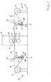
- FIG. 2 shows a rolling mill with the following details.
- a roll stand 12 is built on a foundation 11, in which two superimposed work rolls 13, 14 and two in a vertical alignment with these lying support rollers 15, 16 can be seen. Between the work rolls 13, 14 there is an adjustable or controllable roll gap 17 through which a metal strip 18 passes through from left to right.
- the tape comes from one first reel device 21, from the right-handed reel 22 of the band 18 the top is unwound.
- the tape runs from the reel device 21 into a Tape storage arrangement 23 with tape storage and tensile reinforcement function in the form a double roller assembly consisting of a fixed upper roller 24 and one movable lower roller 25 there. With a circular arrow 26 ' is indicated that the movable roller 25 in the device 23 about the axis the fixed roller 24 can pivot.
- the movable roller 25 can alternatively be adjustable in height.
- a Movement of the movable roller 25 changes in the hereby indicated Executions at least the length of the band strand between the reel 22 and the movable roller 25, in the second case (26 ") also the length of the belt run between the movable roller 25 and the fixed roller 24.
- the lower roller 25 is by means of a rocker 27 from its operating position (25) to an insertion position (25 ') to pivot over the belt line 28.
- the insertion position is with dashed lines (25 ') of the lower roller 25 indicated, in which the band 18 along the likewise Belt line 28 shown in dashed lines can be inserted into the roll stand 12. Only when the band 18 is fixed in the device 33 for reeling does the band pivot Roll 25 back into its operating position (25) shown with solid lines.
- a second reel device 31 is shown for reeling, on the right-handed one Reel 32 the rolled strip 18 is wound over the top.
- a further tape storage arrangement 33 is located on the stand 12 and the device 31 with tape storage and tensile reinforcement function, which consists of a fixed upper roll 34 and a movable lower roller 35.
- the movable roller 35 is opposite the fixed Roller 34 is pivotable about the axis of fixed roller 34, as by a vertical Double arrow 36 "indicated, the movable roller 35 can be moved up and down his.
- the above-mentioned tensile strengthening function results when at least one the rollers 24, 25 with brake means, not shown, and at least one of the rollers 34, 35 is connected to drive means, not shown, and is operated.
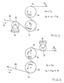
- FIG 3 is a tape storage device on the inlet side of the one to be assumed on the right Roll stand with an upper roller 24 and a lower roller 25 shown in the embodiment shown here, the lower roller 25 preferably the movable one Role is.
- the roll 25 On the side of the reel-off device to be assumed on the left is the roll 25 upstream of a further roller 19, over which the belt 18 is guided and deflected becomes.
- the roller 19 is supported on a fixed web via a load cell 20. When using this load cell, the roller 19 is preferably freely rotatable. However, the roller 19 can also be used to generate a controllable one Braking torque to be connected.
- a tape storage device is on the input side to the one to be assumed on the right Roll nip shown, the upper roller 24 and a lower roller 25th includes.
- the upper roller 24 is preferably controllably movable.
- a further roller 29 is arranged adjacent to the upper roller 24 and has a Load cell 30 is supported on a fixed web. The one running out of the roll 24 Band is deflected by the roller 29.
- Roll 29 is also in use here a load cell 30 preferably freely rotatable. If you do not Load cell can, however, also the role 29 with means for generating a Braking torque are connected.
- the arrangement shown can also be on the output side can be used for the roll gap, in which case the roller 29 may then be controlled Drive means can be connected.
Abstract
Description
Die Erfindung betrifft ein Verfahren zum Warm- oder Kaltwalzen von Metallband, insbesondere zum flexiblen Walzen von Band mit veränderlicher Bandenddicke, mit einer ersten Haspelvorrichtung zum Abhaspeln, von der Band mit einer definierten Bandausgangsdicke abgewickelt wird, einem Walzgerüst, insbesondere einem Reversiergerüst, das zumindest zwei Arbeitswalzen umfaßt, zwischen denen ein in der Weite steuerbarer und/oder regelbarer Walzspalt gebildet wird, einer zweiten Haspelvorrichtung zum Aufhaspeln, auf die Band mit einer gegenüber der definierten Bandausgangsdicke reduzierten Bandenddicke aufgewickelt wird, sowie mit ersten Bandspeichermitteln aus einer Mehrzahl von Rollen zwischen der ersten Haspelvorrichtung und dem Walzgerüst und mit zweiten Bandspeichermitteln aus einer Mehrzahl von Rollen zwischen dem Walzgerüst und der zweiten Haspelvorrichtung, wobei die Rollen der ersten und zweiten Bandspeichermittel zur Bandspeicherung im Betrieb in ihrer Stellung relativ zueinander verändert werden; die Erfindung betrifft weiterhin ein Walzwerk oder eine Walzanlage zum Warm- oder Kaltwalzen von Metallband, insbesondere zum Walzen von Band mit veränderlicher Bandenddicke, mit einer ersten Haspelvorrichtung zum Abhaspeln, von der Band mit einer definierten Bandausgangsdicke abwickelbar ist, einem Walzgerüst, insbesondere einem Reversiergerüst, das zumindest zwei Arbeitswalzen umfaßt, zwischen denen ein in der Weite steuerbarer und/oder regelbarer Walzspalt gebildet wird, einer zweiten Haspelvorrichtung zum Aufhaspeln, auf die Band mit einer gegenüber der definierten Bandausgangsdicke reduzierten Bandenddicke aufwickelbar ist, sowie mit ersten Bandspeichermitteln zwischen der ersten Haspelvorrichtung und dem Walzgerüst und mit zweiten Bandspeichermitteln zwischen dem Walzgerüst und der zweiten Haspelvorrichtung. In solchen Walzanlagen wird vorgewalztes Band auf eine reduzierte Enddicke gewalzt, die mit geringen Toleranzen im in der Weite steuerbaren und/oder regelbaren Walzspalt eingestellt und aufrechterhalten werden kann. Das vorgewalzte Band kann hierbei bereits flexibel gewalztes Band mit veränderlicher Bandausgangsdicke sein.The invention relates to a method for hot or cold rolling metal strip, in particular for flexible rolling of strips with variable strip thickness, with one first reel device for uncoiling, from the band with a defined Strip outlet thickness is unwound, a roll stand, in particular a reversing stand, which comprises at least two work rolls, between which one in the Wide controllable and / or adjustable roll gap is formed, a second reel device for reeling, on the tape with one opposite the defined one Strip output thickness is reduced to the final strip thickness, as well as with the first Tape storage means from a plurality of rolls between the first reel device and the roll stand and with second strip storage means from a plurality of rollers between the roll stand and the second reel device, wherein the roles of the first and second tape storage means for tape storage in operation be changed in their position relative to each other; the invention further relates to a rolling mill or a rolling plant for hot or cold rolling of metal strip, especially for rolling strip with variable strip thickness, with a first reel device for uncoiling, from the band with a defined Strip outlet thickness can be developed, a roll stand, in particular a reversing stand, which comprises at least two work rolls, between which one in the Wide controllable and / or adjustable roll gap is formed, a second reel device for reeling, on the tape with one opposite the defined one Tape output thickness reduced tape thickness is wound, as well as with the first Strip storage means between the first reel device and the roll stand and with second strip storage means between the roll stand and the second Coiler. In such rolling mills, pre-rolled strip is reduced to a reduced one Rolled final thickness, which can be controlled with small tolerances in width and / or adjustable roll gap can be set and maintained. The Pre-rolled strip can already be flexibly rolled strip with variable Tape exit thickness.
Durch das sogenannte flexible Walzen werden Metallbänder mit periodisch wechselnd definiert unterschiedlichen Dicken hergestellt. Das gewalzte Längsdickenprofil entspricht in Länge und Dicke beispielsweise dem späteren Belastungsfall eines Blechbauteils. Der Walzprozeß ist als Kalt- oder Warmbandwalzen auszulegen. Das zu walzende Bandmaterial wird von einem Coil abgehaspelt, gewalzt und anschließend wieder unter Zug aufgehaspelt. Die entsprechenden Walzanlagen können Reversieranlagen sein, d. h. nach Durchlaufen eines Coils von der ersten zur zweiten Haspelvorrichtung kann ein nächster Coil von der zweiten zur ersten Haspelvorrichtung durchlaufen lassen werden. Aus diesem Bandmaterial werden nach entsprechender Nachbehandlung Platinen vereinzelt, die für die Herstellung von Bauteilen mit unterschiedlichen Wandstärken verwendet werden. Als Weiterverarbeitungsprozeß kann in Abhängigkeit von der geforderten Geometrie jedes Blechumformverfahren verwendet werden, z. B. Tiefziehen, Streckziehen, Innenhochdruckumformung, Hochdruckblechumformung.The so-called flexible rolling means that metal strips change periodically defined different thicknesses. The rolled longitudinal thickness profile corresponds in length and thickness, for example, to the later load case Sheet metal component. The rolling process is to be designed as cold or hot strip rolling. The Strip material to be rolled is unwound from a coil, rolled and then rewound under train. The corresponding rolling mills can reverse plants be d. H. after passing through a coil from the first to the second Reel device can be a next coil from the second to the first reel device be run through. From this tape material, according to the corresponding Post-treatment of blanks used for the manufacture of components with different wall thicknesses can be used. As a processing process can do any sheet metal forming process depending on the required geometry are used, e.g. B. deep drawing, stretch drawing, hydroforming, High-pressure metal forming.
Beim flexiblen Walzen werden gravierende Banddickenunterschiede von bis zu 50% in einem einzigen Walzdurchgang (Stich) durch Veränderung des Walzspaltes mittels servo-hydraulischer oder servo-elektrischer Stellmittel für die Arbeitswalzen hergestellt. Bei einer Veränderung des Walzspaltes und damit der auslaufenden Bandenddicke entstehen aus der Bedingung der Volumenkonstanz am Walzspalt ein- und auslaufseitig Veränderungen der Bandgeschwindigkeit. Diese Veränderungen der Bandgeschwindigkeit erfolgen so schnell - beispielsweise innerhalb von 100ms - daß die Haspelgruppen nicht in der Lage sind, konstante Bandzüge am Walzspalt einzuhalten. Veränderungen der Bandzüge haben direkten Einfluß auf die auslaufseitigen Banddickentoleranzen. Um die Banddickentoleranzen zu verbessern, ist demnach ein Verfahren erforderlich, das konstante Bandzüge auch über stark veränderliche Bandgeschwindigkeiten ermöglicht. Hierzu werden seit Jahrzehnten sogenannte Tänzer in die Bandlinie eingesetzt, die in ihrer Funktion als Bandspeichermittel bei Geschwindigkeitsveränderungen den Bandzug konstant halten.With flexible rolling, there are serious strip thickness differences of up to 50% in one roll pass (pass) by changing the roll gap by means of Servo-hydraulic or servo-electric actuators for the work rolls. If the roll gap and thus the final strip thickness change arise from the condition of volume constancy at the roll gap Changes in the belt speed on the exit side. These changes in Belt speed is so fast - for example within 100ms - that the reel groups are unable to produce constant strip tension at the roll gap observed. Changes in the belt tension have a direct influence on the outlet side Strip thickness tolerances. Accordingly, in order to improve the strip thickness tolerances a process is required that allows constant strip tension even over highly variable ones Belt speeds enabled. So-called Dancers used in the band line, which in their function as tape storage means Changes in speed keep the belt tension constant.
Aus der WO 03/008122 A1 oder DE 100 04 532 A1 sind auch bereits Kaltwalzanlagen bekannt geworden, mit denen Warmband mit im wesentlichen konstanter Bandausgangsdicke mit größeren Toleranzen auf periodisch veränderliche Bandenddikken innerhalb geringerer Toleranzen kaltgewalzt werden kann. Hierbei wird die Bandenddicke üblicherweise zwischen zwei verschiedenen Werten periodisch veränderlich eingestellt. Generell sind bei Walzanlagen der genannten Art erste Bandspeichermittel zwischen der Abhaspelvorrichtung und dem Walzgerüst und zweite Bandspeichermittel zwischen dem Walzgerüst und der Aufhaspelvorrichtung erforderlich. Diese Vorrichtungen in Form von Tänzern dienen im wesentlichen dazu, am Walzspalt eine etwa konstante Zugbelastung aufrechtzuerhalten. Beim Walzen von Band mit periodisch wechselnder Bandenddicke haben die Bandspeichermittel darüber hinaus die Aufgabe, die Bandgeschwindigkeiten, die sich eingangsseitig in erheblichem Ausmaß und auch ausgangsseitig in geringerem Ausmaß periodisch verändern, bei im wesentlichen konstanten Haspelgeschwindigkeiten an den Haspeln auszugleichen, da bei einer konstanten Ausgangsdicke und wechselnden Enddicken des Bandmaterials die Eintrittsgeschwindigkeit des Bandmaterials am Walzspalt sprungartig wechselt. Hierbei entstehen besondere Probleme beim Aufhaspeln von Band mit periodisch wechselnder Bandenddicke, auf die nachstehend eingegangen wird. Das aufgewickelte Bandmaterial wird anschließend an das Walzen in aufgewickeltem Zustand geglüht. Hierbei hat sich gezeigt, daß unter zu hohem Zug aufgewickeltes Bandmaterial mit periodisch wechselnder Bandenddicke, das naturgemäß auf der Haspel nicht vollflächig aufeinanderliegt, nach dem Glühen und Auskühlen nicht mehr problemlos abgewickelt werden kann. Dies erfordert es bisher, das aufgewickelte Bandmaterial mit periodisch wechselnder Bandenddicke nach dem Walzen vor dem Glühen zunächst zugfrei umzuwickeln, um dann das Glühen in aufgewickeltem Zustand ohne Beeinträchtigung der problemlosen Abwickelbarkeit durchführen zu können.WO 03/008122 A1 or DE 100 04 532 A1 are also cold rolling mills become known with which hot strip with a substantially constant strip exit thickness with larger tolerances on periodically changing tape end thicknesses can be cold rolled within narrow tolerances. Here, the Band thickness usually varies periodically between two different values set. In general, the first strip storage means are in rolling mills of the type mentioned between the decoiler and the roll stand and second Strip storage means between the roll stand and the reel-up required. These devices in the form of dancers essentially serve maintain an approximately constant tensile load at the roll gap. When rolling of tape with periodically changing tape thickness have the tape storage means In addition, the task of determining the belt speeds that are in the input side considerable extent and also periodically on the output side to a lesser extent change at substantially constant reel speeds on the reels to compensate, since with a constant starting thickness and changing Final thickness of the strip material the entry speed of the strip material on Roll gap changes suddenly. This creates special problems when reeling of strip with periodically changing strip thickness, to the following is received. The wound tape material is then attached to the Rolls annealed in wound condition. It has been shown that under high tension coiled strip material with periodically changing strip thickness, which naturally does not lie completely on top of one another on the reel after annealing and cooling can no longer be handled easily. It requires it so far, the wound strip material with periodically changing strip thickness after rolling before annealing, first wrap without tension, and then the Annealed in the wound state without affecting the problem-free To be able to perform unwindability.
Bisher werden als Bandspeichermittel in den angegebenen Positionen innerhalb der Walzanlage Tänzerrollenanordnungen eingesetzt, die jeweils zwei feste Umlenkrollen und eine senkrecht zur Bandlinie (pass-line) steuerbar bewegliche Tänzerrolle umfassen. Aufgrund des dabei gegebenen Umschlingungswinkels sind mit Anordnungen dieser Art die erforderlichen Zugkräfte für große Dickenänderungen nicht immer sicherzustellen. Im übrigen erfordern solche Tänzerrollenanordnungen eine relativ große Baulänge der Walzanlage bzw. des Walztisches.So far as tape storage means in the specified positions within the Rolling system used dancer roller arrangements, each with two fixed deflection rollers and a dancer roll that can be controlled vertically to the band line (pass-line) include. Due to the wrap angle given there are arrangements this type does not have the required tensile forces for large changes in thickness always ensure. For the rest, such dancer roll arrangements require one relatively large length of the rolling mill or the rolling table.
Aus der DE 302 46 82 A1 ist ein Dressiergerüst mit vom Walzband in S-Form umschlungenen Zugwalzen bekannt, wobei die Zugwalzen mit regelbaren Antriebsmomenten angetrieben werden können oder von ihren Antrieben abgekuppelt werden, um als reine Umlenkrollen zu dienen.DE 302 46 82 A1 describes a skin pass mill with an S-shape wrapped around it by the rolled strip Draw rollers known, the draw rollers with adjustable drive torques can be driven or uncoupled from their drives, to serve as pure pulleys.
Um das Einführen von Bandenden- insbesondere von Bändern mit großer Steife ab einer Dicke von 2-3 mm zu erleichtern, ist jeweils eine der Zugrollen um die andere herum auf deren Gegenseite schwenkbar und nach erfolgtem Einlauf in ihre Arbeitsposition zurückführbar. Die Antriebe der schwenkbaren Zugrollen sind ortsfest, so daß diese Zugrollen im Betrieb ortsfest verriegelt werden müssen. Eine Funktion als Bandspeichermittel ist durch diese Zugwalzen nicht gegeben.To insert tape ends - especially tapes with great stiffness To facilitate a thickness of 2-3 mm, one of the pull rollers is one after the other can be swiveled around on the opposite side and after it has entered its working position recyclable. The drives of the swiveling pull rollers are stationary, so that these pull rollers must be locked in place during operation. A function as Tape storage means is not provided by these pull rollers.
Hiervon ausgehend liegt der vorliegenden Erfindung die Aufgabe zugrunde, ein Verfahren zum Walzen und eine Walzanlage der genannten Art bereitzustellen, durch die Bandspeichermittel mit kurzer Baulänge längs der Bandlinie möglich werden. Eine weiterführende Aufgabe liegt darin, ein Verfahren zum Walzen und eine Walzanlage der genannten Art bereitzustellen, bei der die Bandspeichermittel zum Aufbau hoher Bandzüge geeignet sind.Proceeding from this, the object of the present invention is a method for rolling and to provide a rolling system of the type mentioned, by the tape storage means with a short length along the belt line are possible. A further task is a process for rolling and a rolling mill to provide the type mentioned, in which the tape storage means for construction high belt tension are suitable.
Die Lösung hierfür besteht in einem Verfahren, das sich dadurch auszeichnet, daß das Metallband über zumindest eines der Bandspeichermittel in Form eines "S" mit zumindest teilweise übereinanderliegenden Bögen geführt wird, wobei beim Walzen durch eine aufgezwungene Bewegung zumindest einer der Rollen der Bandspeichermittel das "S" so verzerrt wird, daß die Länge des Metallbandes zwischen dem Einlauf und dem Auslauf in die bzw. aus den Bandspeichermitteln verändert wird. Insbesondere ist hierbei vorgesehen, daß das Metallband über die Bandspeichermittel in Form eines stehenden "S", mit zumindest teilweise in verschiedener Höhe liegenden Bögen, insbesondere mit zwei sich in horizontaler Richtung, d. h. in vertikaler Projektion, zumindest teilweise überdeckenden Bögen geführt wird. Eine weitere Verkürzung der Baulänge ist möglich, wenn die Zentren der übereinanderliegenden Bögen des "S" bei der Bewegung der Rollen zumindest zeitweise vertikal deckungsgleich übereinanderliegen.The solution to this lies in a process which is characterized in that the metal strip with at least one of the tape storage means in the form of an "S" sheets are at least partially superimposed, during the rolling by forced movement of at least one of the rolls of the tape storage means the "S" is distorted so that the length of the metal strip between the Inlet and outlet in or out of the tape storage means is changed. In particular, it is provided that the metal strip over the tape storage means in the form of a standing "S", with at least partially lying at different heights Arches, especially with two in the horizontal direction, d. H. in vertical Projection, at least partially overlapping arches is performed. Another The overall length can be shortened if the centers of the superimposed ones Arches of the "S" at least temporarily vertically congruent when the rollers move superimposed.
Mit der Definition eines "S" ist ein an einer vertikalen Ebene gespiegeltes "S" eingeschlossen. Das "S" hat hierbei zwei Bögen (Kreisbögen) entgegengesetzter Krümmung, die über eine tangential anschließende Gerade verbunden sind.The definition of an "S" includes an "S" mirrored on a vertical plane. The "S" has two arcs (circular arcs) of opposite curvature, which are connected by a tangential line.
Nach einer ersten günstigen Verfahrensführung kann vorgesehen sein, daß der oberer Bogen des "S" in seiner Lage gesteuert und/oder geregelt verändert wird, besonders wenn Geschwindigkeitsstörungen der Bandgeschwindigkeit vom Walzspalt herrühren. Dies ist der Fall, wenn flexibles Walzen mit variabler Bandenddicke zur Anwendung kommt. Nach einer alternativen Verfahrensführung kann vorgesehen sein, daß der untere Bogen des "S" in seiner Lage geregelt und/oder gesteuert verändert wird, und zwar insbesondere bei von der Haspelvorrichtung herrührenden Geschwindigkeitsstörungen. Eine solche Geschwindigkeitsstörung kann durch den sogenannten Bundschlag verursacht werden, d. h. die stufige Durchmesserveränderung am Coil radial über dem innenliegenden Bandanfang des Bandmaterials.After a first favorable procedure, it can be provided that the upper Bow of the "S" is controlled in its position and / or regulated changed, especially when speed disturbances of the strip speed originate from the roll gap. This is the case when using flexible rolling with variable strip thickness comes. According to an alternative procedure, it can be provided that that the lower bow of the "S" changed its position regulated and / or controlled , in particular in the case of speed disturbances originating from the reel device. Such a speed disturbance can be caused by the so-called Covenant caused, d. H. the step change in diameter on the coil radially above the inside band start of the band material.
Eine erfindungsgemäße Walzanlage zeichnet sich dadurch aus, daß zumindest eines der Bandspeichermittel aus einer Doppelrollenanordnung mit S-förmiger Bandumschlingung von zwei Rollen gebildet wird, deren Achsen in der Höhe unterschiedlich angeordnet sind, wobei eine erste Rolle das Band zwischen der Doppelrollenanordnung und dem Walzgerüst auf der Bandlinie (pass-line) spannt und eine zweite Rolle das Band zwischen der Doppelrollenanordnung und der entsprechenden Haspelvorrichtung spannt, und wobei durch eine Bewegung zumindest einer beweglichen der beiden Rollen die Länge des Bandtrums zwischen Haspel und beweglicher Rolle und/oder zwischen der beweglichen Rolle und der weiteren der beiden Rollen beim Walzen veränderbar ist. Hierbei kann die bewegliche Rolle im Betrieb senkrecht zur Bandlinie (pass-line) beweglich sein oder parallel zur Bandlinie (pass-line) beweglich sein oder um eine Drehachse pendelnd angeordnet sein, die außerhalb des Rollenquerschnitts, insbesondere auf der Drehachse der weiteren Rolle liegt. Mit der hiermit vorgeschlagenen Anordnung mit zwei übereinanderliegenden Rollen der Bandspeichermittel ist zum einen eine axial kurze Bauweise, zum anderen eine große Rollenumschlingung möglich. Mit einer derartigen Rollenumschlingung ist ein hoher Bandzug am Walzspalt aufzubauen. Bevorzugt weisen die Bandspeichermittel gerade nur diese zwei übereinanderliegenden Rollen auf. Bevorzugt ist hierbei eine im wesentlichen symmetrische Ausführung der Bandspeichermittel, bei der also sowohl vor dem Walzgerüst als auch hinter dem Walzgerüst eine erfindungsgemäße Doppelrollenanordnung verwendet wird. Die Verstellung der beweglichen Rollen kann mit geeigneten servo-hydraulischen oder servo-elektrischen Stellmitteln erfolgen, die eine Aufrechterhaltung hoher Zugkräfte bei kurzen Reaktionszeiten ermöglichen. Bei Variation der jeweiligen Bandenddicke, d. h. bei Änderung des eingestellten Walzspalts, ist eine konstante Bandzugkraft ohne Einschwingeffekte durch eine erfindungsgemäße Doppelrollenanordnung ohne großen zeitlichen Verzug einzuregeln.A rolling mill according to the invention is characterized in that at least one the tape storage means from a double roller arrangement with S-shaped belt wrap is formed by two roles, the axes of which differ in height are arranged, with a first roller the belt between the double roller arrangement and the roll stand on the belt line (pass-line) and a second roll the belt between the double roller assembly and the corresponding reel device spans, and being by a movement of at least one movable the the length of the belt run between the reel and the movable reel for both reels and / or between the movable role and the other of the two roles in Rolling is changeable. Here, the movable roller can be perpendicular to the operation Belt line (pass-line) can be movable or movable parallel to the belt line (pass-line) be or be arranged to oscillate about an axis of rotation that is outside the roller cross section, lies in particular on the axis of rotation of the further roller. With this proposed arrangement with two superposed rolls of tape storage means is on the one hand an axially short design, on the other hand a large roller wrap possible. With such a roll wrap is a high one Set up the strip tension at the roll gap. The tape storage means preferably point straight just these two superimposed roles. An im is preferred essentially symmetrical design of the tape storage means, so both a double roller arrangement according to the invention in front of the roll stand and also behind the roll stand is used. The moving rollers can be adjusted with suitable servo-hydraulic or servo-electric actuators, which enable maintenance of high tractive forces with short reaction times. at Variation of the respective final strip thickness, d. H. when changing the set roll gap, is a constant belt tension without transient effects by an inventive Adjust double roller arrangement without great delay.
Nach einer ersten Ausführungsform kann eine bewegliche Rolle über einer weiteren Rolle angeordnet sein, insbesondere wenn eine Störung der Bandgeschwindigkeit von Walzspalt ausgeht, also beim flexiblen Walzen wie oben erwähnt. Hierbei läuft das Band in den ersten Bandspeichermitteln an der weiteren Rolle ein und an der beweglichen Rolle aus und in den zweiten Bandspeichermitteln an der beweglichen Rolle ein und an der weiteren Rolle aus.According to a first embodiment, a movable roller can be placed over another Roll be arranged, especially if there is a disturbance of the belt speed starts from the roll gap, i.e. in flexible rolling as mentioned above. Here runs the tape in the first tape storage means on the further roll and on the movable roll from and in the second tape storage means on the movable Roll in and out of the further role.
Nach einer weiteren Ausführung kann eine bewegliche Rolle unter einer weiteren Rolle angeordnet sein, nämlich insbesondere wenn eine Störung der Bandgeschwindigkeit durch den Bundschlag von der Haspelvorrichtung ausgeht. Hierbei läuft in den ersten Bandspeichermitteln das Band an der beweglichen Rolle ein und an der weiteren Rolle aus, während bei den zweiten Bandspeichermitteln das Band an der weiteren Rolle ein und an der beweglichen Rolle ausläuft.According to another embodiment, a movable roller can be placed under another Roll be arranged, namely especially if a disturbance of the belt speed starts from the reel device by means of the collar. Here runs in the first tape storage means the tape on the movable roller and on the further role, while in the second tape storage means the tape on the another role and runs out on the movable role.
Die jeweils untere Rolle kann zum Einführen eines Bandanfangs von der Abhaspelvorrichtung in den Walzspalt und von dort auf die Aushaspelvorrichtung aus einer Betriebsposition in eine Einführposition auf die entgegengesetzte Seite der Bandlinie, also nach oberhalb der Bandlinie schwenkbar ausgeführt sein. Nach dem entsprechenden Fixieren des Bandanfangs auf der Aufhaspelvorrichtung kann die jeweils untere Rolle in ihre Betriebsposition zurückgeschwenkt werden, wobei dann das Band S-förmig um die schwenkbare untere Rolle und die im wesentlichen ortsfeste obere Rolle gezogen wird. Das Abwickeln von der Abhaspelvorrichtung ebenso wie das Aufwickeln auf die Aufhaspelvorrichtung kann bevorzugt über die Unterseite der entsprechenden Haspeln erfolgen. Dies ermöglicht einem Bediener eine gleichzeitige visuelle Bandkontrolle auf beiden Bandseiten. Das Abwickeln und Aufwickeln kann auch über die Oberseite der Haspeln erfolgen, z. B. um den Umschlingungswinkel an den Bandspeichermitteln günstig zu beeinflussen.The respective lower roll can be used to insert a beginning of the tape from the uncoiler into the roll gap and from there onto the uncoiler from one Operating position in an insertion position on the opposite side of the belt line, thus be designed to be pivotable above the belt line. After the corresponding one Fixing the beginning of the tape on the reel can each lower roller are pivoted back into their operating position, which then Band S-shaped around the swiveling lower roller and the essentially stationary upper roller is pulled. Unwinding from the uncoiler as well the winding onto the reel-up device can preferably be carried out via the underside of the appropriate reels. This enables an operator to simultaneously visual tape control on both sides of the tape. Unwinding and rewinding can also done over the top of the reels, e.g. B. by the wrap angle to influence the tape storage means favorably.
Eine bevorzugte Ausführung besteht in einem Verfahren der eingangs genannten Art, welches sich dadurch auszeichnet, daß zumindest eine Rolle der ersten Bandspeichermittel zur Zugverstärkung am Walzspalt mit steuerbar und/oder regelbar veränderlichem Bremsmoment abgebremst wird und zumindest eine Rolle der zweiten Bandspeichermittel zur Zugverstärkung am Walzspalt mit steuerbar und/oder regelbar veränderlichem Antriebsmoment angetrieben wird. Mit diesen Mitteln können die Bandzüge am Walzspalt erheblich erhöht werden, während die Brems- bzw. Antriebsmomente an den Haspeln, die bei Walzanlagen nach dem Stand der Technik für den Aufbau der Bandzugkräfte ausschlaggebend sind, wesentlich reduziert werden können. Absolut betrachtet ist hiermit eine Bandzugverstärkung am Walzspalt möglich.A preferred embodiment consists in a method of the aforementioned Type, which is characterized in that at least one role of the first tape storage means for tensile reinforcement at the roll gap with controllable and / or adjustable variable braking torque is braked and at least one role of the second Strip storage means for tensile reinforcement at the roll gap can be controlled and / or regulated variable drive torque is driven. With these means you can the strip tension at the roll gap can be increased significantly while the braking or driving torques on the reels used in state-of-the-art rolling mills crucial for the development of the tape tensile forces can be significantly reduced can. In absolute terms, this is a strip tension reinforcement at the roll gap possible.
Nach einer günstigen Weiterbildung kann vorgesehen werden, daß das Bremsmoment der genannten Rolle der ersten Bandspeichermittel und das Antriebsmoment der genannten Rolle der zweiten Bandspeichermittel beim Walzen von Band mit veränderlicher Banddicke auf konstanten Bandzug gesteuert und/oder geregelt wird. Weiterhin ist es möglich, daß die Steuerung und/oder Regelung des Bandzugs durch Veränderung des Bremsmomentes an mehreren Rollen der ersten Bandspeichermitteln und/oder durch Veränderung des Antriebsmomentes an mehreren Rollen der zweiten Bandspeichermitteln erfolgt. Eine weitere Ausgestaltung geht dahin, daß die Steuerung und/oder Regelung des Bandzugs zusätzlich durch Änderung der relativen Rollenpositionen der Rollen der ersten Bandspeichermitteln und/oder der relativen Rollenpositionen der Rollen der zweiten Bandspeichermitteln erfolgt. According to a favorable development, it can be provided that the braking torque the aforementioned role of the first tape storage means and the drive torque the aforementioned role of the second strip storage means when rolling strip with variable Strip thickness is controlled and / or regulated to constant strip tension. It is also possible that the control and / or regulation of the tape tension by Change in the braking torque on several roles of the first tape storage means and / or by changing the drive torque on several roles of second tape storage means. Another embodiment is that the Control and / or regulation of the strip tension additionally by changing the relative Role positions of the roles of the first tape storage means and / or the relative Roll positions of the roles of the second tape storage means takes place.
Eine vorteilhafte Ausführung einer der genannten Art ist dadurch gekennzeichnet, daß zumindest eine Rolle der ersten Bandspeichermittel mit Mitteln zur Erzeugung von gesteuert und/oder geregelt veränderbaren Bremsmomenten verbunden ist und zumindest eine Rolle der zweiten Bandspeichermittel mit Mitteln zur Erzeugung von gesteuert und/oder geregelt veränderbaren Antriebsmomenten verbunden ist. Hiermit ist eine Zugverstärkung, d. h. eine Erhöhung des Bandzuges zwischen Haspel und Walzspalt auf der Eingangs- und auf der Ausgangsseite, möglich, anders als bei Tänzeranordnungen nach dem Stand der Technik, bei denen nur die relativen Rollenpositionen zur Aufrechterhaltung konstanten Bandzuges kraftgeregelt und verstellt werden, im übrigen jedoch die Rollen frei drehen.An advantageous embodiment of one of the types mentioned is characterized in that that at least one role of the first tape storage means with means for generation is connected by controlled and / or regulated changeable braking torques and at least one role of the second tape storage means with means for generating controlled and / or regulated changeable drive torque is connected. Herewith is a train reinforcement, i.e. H. an increase in the band tension between reel and Roll gap on the input and on the output side, possible, unlike at State-of-the-art dancer arrangements in which only the relative role positions force-controlled and adjusted to maintain constant belt tension are, but otherwise rotate the roles freely.
Nach einer weiteren Ausführungsform ist vorgesehen, daß die Mittel zur Erzeugung der Bremsmomente und/oder die Mittel zu Erzeugung der Antriebsmomente durch elektrische Maschinen (Generator/E-Motor) gebildet werden. Eine Alternative hierzu besteht darin, daß die Mittel zur Erzeugung der Bremsmomente und/oder die Mittel zur Erzeugung der Antriebsmomente durch hydrostatische Maschinen (Hydropumpe/Hydromotor) gebildet werden.According to a further embodiment it is provided that the means for generating the braking torques and / or the means for generating the driving torques electrical machines (generator / electric motor) are formed. An alternative to this is that the means for generating the braking torques and / or the means to generate the drive torques by hydrostatic machines (hydraulic pump / hydraulic motor) be formed.
Bevorzugt sind jeweils zwei Rollen der erfindungsgemäßen Bandspeicher- und Bandzugmitteln ebenso wie die Arbeitswalzen und die Haspeln antreibbar. Hierbei muß eine erfindungsgemäße Doppelrollenanordnung vor dem Walzgerüst ein Bremsmoment gegenüber den Arbeitswalzen aufbauen und eine erfindungsgemäße Doppelrollenanordnung hinter dem Walzgerüst ein Antriebsmoment gegenüber den Arbeitswalzen.Two roles of the tape storage and are preferred Belt traction means as well as the work rolls and the reels can be driven. in this connection must a double roller assembly according to the invention in front of the roll stand Build braking torque against the work rolls and an inventive Double roller arrangement behind the roll stand a drive torque compared to Work rolls.
In bevorzugter Ausführung können den Bandspeichermitteln weitere frei drehende Rollen oder weitere abbremsbare bzw. antreibbare Rollen unmittelbar vor- oder nachgeordnet sein. Hierbei kann jeweils eine Rolle zur Messung des Bandzuges über eine Kraftmeßdose an einem festen Steg abgestützt sein, deren Meßwert in die Regelung auf konstantem Bandzug am Walzspalt eingeht.In a preferred embodiment, the tape storage means can rotate freely Roles or other brakable or drivable roles immediately forward or be subordinate. In this case, one role can be used to measure the strip tension be supported by a load cell on a fixed web, the measured value in the Control on constant strip tension at the roll gap is received.
Zwischen den im einzelnen angesprochenen Komponenten Haspelvorrichtungen, Bandspeicher- und Bandzugmitteln und Walzgerüst können weitere Anlagenteile in Form von Rollentischen oder ähnlichem zur Führung des Bandes längs der Bandlinie vorhanden sein.Between the components referred to in detail, reel devices, Belt storage and belt tensioning means and roll stand can further plant parts in Form of roller tables or the like for guiding the belt along the belt line to be available.
Bevorzugte Ausführungsbeispiele der Erfindung sind in den Zeichnungen dargestellt.
- Figur 1
- zeigt eine erfindungsgemäße Walzanlage als Prinzipbild in Seitenansicht in einer ersten Ausführung;
- Figur 2
- zeigt eine erfindungsgemäße Walzanlage als Prinzipbild in Seitenansicht in einer zweiten Ausführung;
- Figur 3
- zeigt Bandspeichermittel auf der Einlaufseite als Einzelheit in einer ersten Ausführung;
- Figur 4
- zeigt Bandspeichermittel auf der Einlaufseite als Einzelheit in einer zweiten Ausführung;
- Figure 1
- shows a rolling plant according to the invention as a schematic in side view in a first embodiment;
- Figure 2
- shows a rolling plant according to the invention as a schematic in side view in a second embodiment;
- Figure 3
- shows tape storage means on the entry side as a detail in a first embodiment;
- Figure 4
- shows tape storage means on the entry side as a detail in a second embodiment;
Figur 1 zeigt eine Walzanlage mit den folgenden Einzelheiten.Figure 1 shows a rolling mill with the following details.
Auf einem Fundament 11 ist ein Walzgerüst 12 aufgebaut, in dem zwei übereinanderliegende
Arbeitswalzen 13, 14 und zwei in einer vertikalen Flucht mit diesen liegende
Stützwalzen 15, 16 zu erkennen sind. Zwischen den Arbeitswalzen 13, 14 befindet
sich ein einstellbarer bzw. steuerbarer Walzspalt 17, durch welchen ein Metallband
18 von links nach rechts durchläuft. Das Band kommt von einer ersten Haspelvorrichtung
21, von deren linksdrehender Haspel 22 das Band 18 über die Unterseite
abgewickelt wird. Von der Haspelvorrichtung 21 läuft das Band in eine Bandspeicheranordnung
23 mit Bandspeicher- und Zugverstärkungsfunktion in Form einer
Doppelrollenanordnung, die aus einer beweglichen oberen Rolle 24 und einer festen
unteren Rolle 25 besteht. Mit einem horizontalen Doppelpfeil 26 ist angedeutet, daß
die bewegliche Rolle 24 in der Vorrichtung 23 gesteuert horizontal verschoben werden
kann. Eine Bewegung der beweglichen Rolle 24 ändert in der hiermit angedeuteten
Ausführung die Länge des Bandtrums zwischen der beweglichen Rolle 24 und
dem Walzspalt 17, und ebenfalls die Länge des Bandtrums zwischen der beweglichen
Rolle 24 und der festen Rolle 25. Die untere, an sich feste Rolle 25, ist mittels
einer Schwinge 27 aus ihrer Betriebsposition (25) in eine Einführposition (25') über
der Bandlinie 28 zu schwenken. Mit gestrichelten Linien ist die Einführposition (25')
der unteren Rolle 25 angedeutet, in der das Band 18 längs der ebenfalls gestrichelt
dargestellten Bandlinie 28 in das Walzgerüst 12 eingeführt werden kann. Erst wenn
das Band 18 in der Vorrichtung 33 zum Aufhaspeln fixiert ist, schwenkt die Rolle 25
in ihre mit durchgezogenen Linien dargestellte Betriebsposition (25) zurück.A roll stand 12 is built on a foundation 11, in which two superposed ones
Work rolls 13, 14 and two lying in a vertical alignment with these
Back-up rolls 15, 16 can be seen. Located between the work rolls 13, 14
there is an adjustable or
In Produktionsrichtung hinter dem Gerüst 12 und damit rechts von dem Gerüst ist
eine zweite Haspelvorrichtung 31 zum Aufhaspeln gezeigt, auf dessen linksdrehende
Haspel 32 das gewalzte Band 18 über die Unterseite aufgewickelt wird. Zwischen
Gerüst 12 und Vorrichtung 31 liegt eine weitere Bandspeicheranordnung 33 mit
Bandspeicher- und Zugverstärkungsfunktion, die aus einer beweglichen oberen Rolle
34 und einer festen unteren Rolle 35 besteht. Wie durch einen horizontalen Doppelpfeil
36 angedeutet, ist die bewegliche Rolle 35 gegenüber der festen Rolle 34 in der
Vorrichtung 33 gesteuert verschiebbar. Hiermit ändert sich gleichzeitig die Länge des
Bandtrums zwischen der beweglichen Rolle 34 und der festen Rolle 35 wie auch die
Länge de Bandtrums zwischen der beweglichen Rolle 34 und dem Walzspalt 17. Mit
gestrichelten Linien ist die Rolle 35 in einer mittels einer Schwinge 37 aus ihrer Betriebsposition
(35) über die Bandlinie 28' geschwenkten Einführposition (35') gezeigt,
die zum Einführen eines Bandanfangs längs der wiederum gestrichelt dargestellten
Bandlinie 28' dient. Wenn der Bandanfang auf der Haspel 32 fixiert ist, schwenkt die
Rolle 35 in ihre durchgezogen dargestellte Betriebsstellung (35) zurück. Neben den
hier dargestellten Bewegungsmöglichkeiten der beweglichen Rollen 24, 34 sind andere
Bewegungen denkbar, wie sie in Figur 2 noch dargestellt werden.In the direction of production behind the
Die oben genannte Zugverstärkungsfunktion ergibt sich dann, wenn zumindest eine
der Rollen 24, 25 mit nicht dargestellten Bremsmitteln und zumindest eine der Rollen
34, 35 mit nicht dargestellten Antriebsmitteln verbunden ist und betrieben wird.The above-mentioned tensile strengthening function results when at least one
the
Figur 2 zeigt eine Walzanlage mit folgenden Einzelheiten. Figure 2 shows a rolling mill with the following details.
Auf einem Fundament 11 ist ein Walzgerüst 12 aufgebaut, in dem zwei
übereinanderliegende Arbeitswalzen 13, 14 und zwei in einer vertikalen Flucht mit
diesen liegende Stützwalzen 15, 16 zu erkennen sind. Zwischen den Arbeitswalzen
13, 14 befindet sich ein einstellbarer bzw. steuerbarer Walzspalt 17, durch welchen
ein Metallband 18 von links nach rechts durchläuft. Das Band kommt von einer
ersten Haspelvorrichtung 21, von deren rechtsdrehender Haspel 22 das Band 18 auf
der Oberseite abgespult wird. Von der Haspelvorrichtung 21 läuft das Band in eine
Bandspeicheranordnung 23 mit Bandspeicher- und Zugverstärkungsfunktion in Form
einer Doppelrollenanordnung, die aus einer festen oberen Rolle 24 und einer
beweglichen unteren Rolle 25 besteht. Mit einem kreisbogenförmigen Doppelpfeil 26'
ist angedeutet, daß die bewegliche Rolle 25 in der Vorrichtung 23 etwa um die Achse
der festen Rolle 24 schwenken kann. Mit einem vertikalen Doppelpfeil 26" ist
angedeutet, daß die bewegliche Rolle 25 alternativ höhenverstellbar sein kann. Eine
Bewegung der beweglichen Rolle 25 ändert in den hiermit angedeuteten
Ausführungen zumindest die Länge des Bandtrums zwischen der Haspel 22 und der
beweglichen Rolle 25, im zweiten Fall (26") auch die Länge des Bandtrums
zwischen der beweglichen Rolle 25 und der festen Rolle 24. Die untere Rolle 25 ist
mittels einer Schwinge 27 aus ihrer Betriebsposition (25) in eine Einführposition (25')
über der Bandlinie 28 zu schwenken. Mit gestrichelten Linien ist die Einführposition
(25') der unteren Rolle 25 angedeutet, in der das Band 18 längs der ebenfalls
gestrichelt dargestellten Bandlinie 28 in das Walzgerüst 12 eingeführt werden kann.
Erst wenn das Band 18 in der Vorrichtung 33 zum Aufhaspeln fixiert ist, schwenkt die
Rolle 25 in ihre mit durchgezogenen Linien dargestellte Betriebsposition (25) zurück.A roll stand 12 is built on a foundation 11, in which two
superimposed work rolls 13, 14 and two in a vertical alignment with
these lying
In Produktionsrichtung hinter dem Gerüst 12 und damit rechts von dem Gerüst ist
eine zweite Haspelvorrichtung 31 zum Aufhaspeln gezeigt, auf dessen rechtsdrehende
Haspel 32 das gewalzte Band 18 über die Oberseite aufgewickelt wird. Zwischen
Gerüst 12 und Vorrichtung 31 liegt eine weitere Bandspeicheranordnung 33
mit Bandspeicher- und Zugverstärkungsfunktion, die aus einer festen oberen Rolle
34 und einer beweglichen unteren Rolle 35 besteht. Wie durch einen kreisbogenförmigen
Doppelpfeil 36' angeordnet, ist die bewegliche Rolle 35 gegenüber der festen
Rolle 34 etwa um die Achse der festen Rolle 34 schwenkbar, wie durch einen vertikalen
Doppelpfeil 36" angedeutet, kann die bewegliche Rolle 35 auf- und abbeweglich
sein. Hiermit ändert sich zumindest die Länge de Bandtrums zwischen der beweglichen
Rolle 35 und der Haspel 32, im zweiten Fall (36") auch die Länge des
Bandtrums zwischen der festen Rolle 34 und der beweglichen Rolle 35. Mit gestrichelten
Linien ist die Rolle 35 in einer mittels einer Schwinge 37 aus ihrer Betriebsposition
(35) über die Bandlinie 28' geschwenkten Einführposition (35') gezeigt, die
zum Einführen eines Bandanfangs längs der wiederum gestrichelt dargestellten
Bandlinie 28' dient. Wenn der Bandanfang auf der Haspel 32 fixiert ist, schwenkt die
Rolle 35 in ihre durchgezogen dargestellte Betriebsstellung (35) zurück. Neben den
hier dargestellten beiden Bewegungsmöglichkeiten der beweglichen Rollen 25, 35 ist
in der Betriebsstellung eine Bewegung der beweglichen Rolle parallel zur Bandlinie
28, also horizontal denkbar, wie sie in Figur 1 gezeigt wurde.In the direction of production behind the
Die oben genannte Zugverstärkungsfunktion ergibt sich dann, wenn zumindest eine
der Rollen 24, 25 mit nicht dargestellten Bremsmitteln und zumindest eine der Rollen
34, 35 mit nicht dargestellten Antriebsmitteln verbunden ist und betrieben wird.The above-mentioned tensile strengthening function results when at least one
the
Je größer die Umschlingung der Rollen 24, 25, 34, 35 durch das Band 18 ist, um so
größere Bandzugkräfte können von den Bandspeicher- und Zugverstärkungsmitteln
aufgebaut werden. Hierbei sollen die Bandzugkräfte am Gerüst 12 bzw. im Walzspalt
17 hoch sein, während die Haspeln 22, 32 möglichst weitgehend von Zugkräften entlastet
werden sollen. Weitere Abwandlungsmöglichkeiten stehen dem Fachmann im
Rahmen des oben offenbarten zur Verfügung.The greater the wrap of the
In Figur 3 ist eine Bandspeichervorrichtung auf der Einlaufseite des rechts anzunehmenden
Walzgerüsts mit einer oberen Rolle 24 und einer unteren Rolle 25 gezeigt,
wobei in der hier gezeigten Ausführung bevorzugt die untere Rolle 25 die bewegliche
Rolle ist. Auf Seite der links anzunehmenden Vorrichtung zum Abhaspeln ist der Rolle
25 eine weitere Rolle 19 vorgeschaltet, über die das Band 18 geführt und umgelenkt
wird. Die Rolle 19 ist über eine Kraftmeßdose 20 an einem festen Steg abgestützt.
Bei Einsatz dieser Kraftmeßdose ist die Rolle 19 bevorzugt frei drehbar gelagert.
Die Rolle 19 kann jedoch auch mit Mitteln zur Erzeugung eines steuerbaren
Bremsmomentes verbunden sein. In Figure 3 is a tape storage device on the inlet side of the one to be assumed on the right
Roll stand with an
In spiegelsymmetrischer Umkehr kann die gezeigte Anordnung ausgangsseitig zum
Walzspalt verwendet werden, wobei dann gegebenenfalls die Rolle 19 mit steuerbaren
Antriebsmitteln verbunden werden kann.In mirror-symmetrical reversal, the arrangement shown on the output side can
Roll gap are used, in which case the
In Figur 4 ist eine Bandspeichervorrichtung auf der Eingangsseite zum rechts anzunehmenden
Walzspalt dargestellt, die eine obere Rolle 24 und eine untere Rolle 25
umfaßt. In dieser Konfiguration ist bevorzugt die obere Rolle 24 steuerbar beweglich.
Benachbart zur oberen Rolle 24 ist eine weitere Rolle 29 angeordnet, die über eine
Kraftmeßdose 30 an einem festen Steg abgestützt ist. Das von der Rolle 24 ablaufende
Band wird durch die Rolle 29 umgelenkt. Auch hier ist die Rolle 29 bei Verwendung
einer Kraftmeßdose 30 vorzugsweise frei drehbar. Bei Verzicht auf die
Kraftmeßdose kann jedoch auch die Rolle 29 mit Mitteln zur Erzeugung eines
Bremsmomentes verbunden werden.In Figure 4, a tape storage device is on the input side to the one to be assumed on the right
Roll nip shown, the
In spiegelsymmetrischer Umkehr kann die gezeigte Anordnung auch ausgangsseitig
zum Walzspalt verwendet werden, wobei dann gegebenenfalls die Rolle 29 mit steuerbaren
Antriebsmitteln verbunden werden kann.In mirror-symmetrical reversal, the arrangement shown can also be on the output side
can be used for the roll gap, in which case the
In den Figuren 3 und 4 sind die Beziehungen der Abwickelgeschwindigkeit Vo, der Einlaufgeschwindigkeit Ve und der Rollenbewegungsgeschwindigkeit VR bei konstanten Rollendrehzahlen w(Vo) während einer Bandspeicherphase eingetragen. The relationships of the unwinding speed V o , the running-in speed V e and the roll movement speed V R at constant roll speeds w (V o ) during a tape storage phase are entered in FIGS. 3 and 4.
- 1111
- Fundamentfoundation
- 1212
- Walzgerüstrolling mill
- 1313
- ArbeitswalzeStripper
- 1414
- ArbeitswalzeStripper
- 1515
- Stützwalzesupporting roll
- 1616
- Stützwalzesupporting roll
- 1717
- Walzspaltnip
- 1818
- Bandtape
- 1919
- Rollerole
- 2020
- Kraftmeßdoseload cell
- 2121
- Haspelvorrichtungcoiler
- 2222
- Haspelreel
- 2323
- BandspeicheranordnungTape storage arrangement
- 2424
- obere Rolletop roll
- 2525
- untere Rollelower roll
- 2626
- Doppelpfeildouble arrow
- 2727
- Schwingewing
- 2828
- Bandlinieband line
- 2929
- Rollerole
- 3030
- Kraftmeßdoseload cell
- 3131
- Haspelvorrichtung coiler
- 3232
- Haspelreel
- 3333
- BandspeicheranordnungTape storage arrangement
- 3434
- obere Rolletop roll
- 3535
- untere Rollelower roll
- 3636
- Doppelpfeildouble arrow
- 3737
- Schwingewing
Claims (26)
dadurch gekennzeichnet, daß das Metallband (18) über zumindest eines der Bandspeichermittel (23, 33) in Form eines "S" geführt wird, wobei beim Walzen durch gesteuerte und/oder geregelte Bewegung zumindest einer der Rollen (24, 25, 34, 35) der Bandspeichermittel (23, 33) das S so verzerrt wird, daß die Länge des Metallbandes zwischen dem Einlauf und dem Auslauf in die bzw. aus den Bandspeichermitteln (23, 33) verändert wird. Method for hot or cold rolling of metal strip (18), in particular for flexible rolling of strip with variable final strip thickness, with a first reel device (21) for uncoiling, from which strip (18) with a defined initial strip thickness is unwound, a roll stand (12) , in particular a reversing stand which comprises at least two work rolls (13, 14), between which a roll gap (17) which can be controlled and / or regulated is formed, a second reel device (31) for reeling onto the belt (18) a reduced strip end thickness compared to the defined strip exit thickness, and with first strip storage means (23) consisting of a plurality of rolls between the first reel device (21) and the roll stand (12), and with second strip storage means (33) consisting of a plurality of rolls between the Roll stand (12) and the second reel device (31), the rollers of the first and second strip storage means for strip storage g are changed in their position relative to each other,
characterized in that the metal strip (18) is guided over at least one of the strip storage means (23, 33) in the form of an "S", with at least one of the rollers (24, 25, 34, 35 ) the tape storage means (23, 33) the S is distorted so that the length of the metal strip between the inlet and the outlet in or out of the tape storage means (23, 33) is changed.
dadurch gekennzeichnet, daß das Metallband (18) über die Bandspeichermittel (23, 33) in Form eines stehenden S, mit zumindest teilweise in verschiedener Höhe liegenden Bögen, insbesondere mit sich in vertikaler Projektion zumindest teilweise überdeckenden Bögen geführt wird.Method according to claim 1,
characterized in that the metal strip (18) is guided over the strip storage means (23, 33) in the form of a standing S, with arches lying at least partially at different heights, in particular with arches overlapping at least partially in vertical projection.
dadurch gekennzeichnet, daß die Zentren der übereinanderliegenden Bögen des S bei der Bewegung der Rollen zumindest zeitweise vertikal übereinanderliegen.Method according to claim 2,
characterized in that the centers of the superposed arches of the S lie at least temporarily vertically one above the other when the rollers are moved.
dadurch gekennzeichnet, daß der obere Bogen des "S" in seiner Lage verändert wird, insbesondere bei einer vom Walzspalt (17) herrührenden Geschwindigkeitsstörung.Method according to one of claims 1 to 3,
characterized in that the position of the upper curve of the "S" is changed, in particular in the event of a speed disturbance resulting from the roll gap (17).
dadurch gekennzeichnet, daß der untere Bogen des "S" in seiner Lage verändert wird, insbesondere bei einer von den Haspelvorrichtungen (22, 32) herrührenden Geschwindigkeitsstörung. Method according to one of claims 1 to 3,
characterized in that the position of the lower curve of the "S" is changed, in particular in the event of a speed disturbance caused by the reel devices (22, 32).
dadurch gekennzeichnet, daß zumindest eine Rolle (24, 25) der ersten Bandspeichermittel (23) zur Verstärkung des Bandzugs am Walzspalt (17) mit steuerbarem und/oder regelbarem Bremsmoment abgebremst wird und zumindest eine Rolle (34, 35) der zweiten Bandspeichermittel (33) zur Verstärkung des Bandzugs am Walzspalt (17) mit steuerbarem und/oder regelbarem Antriebsmoment angetrieben wird.Method for hot or cold rolling of metal strip (18), in particular for flexible rolling of strip with variable final strip thickness, with a first reel device (21) for uncoiling, from which strip (18) is unwound with a defined initial strip thickness, a roll stand (12) , in particular a reversing stand which comprises at least two work rolls (13, 14), between which a roll gap (17) which can be controlled and / or regulated is formed, a second reel device (31) for reeling onto the belt (18) a reduced strip end thickness compared to the defined strip exit thickness, and with first strip storage means (23) consisting of a plurality of rolls between the first reel device (21) and the roll stand (12), and with second strip storage means (33) consisting of a plurality of rolls between the Roll stand (12) and the second reel device (31), the rollers of the first and second strip storage means for strip storage g are changed in their position relative to one another, in particular according to one of claims 1 to 5,
characterized in that at least one roller (24, 25) of the first strip storage means (23) for increasing the strip tension at the roll gap (17) is braked with a controllable and / or adjustable braking torque and at least one roller (34, 35) of the second strip storage means (33 ) is driven to reinforce the strip tension at the roll gap (17) with controllable and / or regulatable drive torque.
dadurch gekennzeichnet, daß das Bremsmoment der Rolle der ersten Bandspeichermittel (23) und das Antriebsmoment der Rolle der zweiten Bandspeichermittel (33) beim Walzen von Band (18) mit veränderlicher Banddicke auf konstanten Bandzug geregelt wird. Method according to claim 6,
characterized in that the braking torque of the roll of the first strip storage means (23) and the driving torque of the roll of the second strip storage means (33) are regulated to a constant strip tension when rolling strip (18) with a variable strip thickness.
dadurch gekennzeichnet, daß die Steuerung und/oder Regelung des Bandzugs durch Veränderung des Bremsmomentes an mehreren Rollen der ersten Bandspeichermittel (23) und/oder durch Veränderung des Antriebsmomentes an mehreren Rollen der zweiten Bandspeichermittel (33) erfolgt.Method according to one of claims 6 or 7,
characterized in that the control and / or regulation of the belt tension takes place by changing the braking torque on several rollers of the first belt storage means (23) and / or by changing the drive torque on several rollers of the second belt storage means (33).
dadurch gekennzeichnet, daß die Steuerung und/oder Regelung des Bandzugs zusätzlich durch Änderung der relativen Rollenpositionen der Rollen der ersten Bandspeichermittel (23) und/oder der relativen Rollenpositionen der Rollen der zweiten Bandspeichermittel (33) erfolgt.Method according to one of claims 6 to 8,
characterized in that the control and / or regulation of the strip tension is additionally effected by changing the relative roll positions of the rolls of the first strip storage means (23) and / or the relative roll positions of the rolls of the second strip storage means (33).
einer zweiten Haspelvorrichtung (31) zum Aufhaspeln, auf die Band (18) mit einer gegenüber der definierten Bandausgangsdicke reduzierten Bandenddicke aufwickelbar ist, sowie mit ersten Bandspeichermitteln (23) aus einer Mehrzahl von Rollen zwischen der ersten Haspelvorrichtung (21) und dem Walzgerüst (12) und mit zweiten Bandspeichermitteln (33) aus einer Mehrzahl von Rollen zwischen dem Walzgerüst (12) und der zweiten Haspelvorrichtung (31),
dadurch gekennzeichnet, daß zumindest eines der Bandspeichermittel (23, 33) aus einer Doppelrollenanordnung mit S-förmiger Bandumschlingung von zwei Rollen (24, 25; 34, 35) gebildet wird, deren Achsen in der Höhe unterschiedlich angeordnet sind, wobei eine erste Rolle (24, 34) das Band (18) zwischen der Doppelrollenanordnung (23, 33) und dem Walzgerüst (12) spannt und eine zweite Rolle (25, 35) das Band (18) zwischen der Doppelrollenanordnung (23, 33) und der entsprechenden Haspelvorrichtung (21, 31) spannt und durch eine Bewegung zumindest einer beweglichen Rolle (24, 34; 25, 35) die Länge des Bandtrums zwischen Haspelvorrichtung (21, 31) und zweiter Rolle (25, 35) und/oder zwischen zweiter Rolle (25, 35) und erster Rolle (24, 34) beim Walzen veränderbar ist.Rolling plant for hot or cold rolling of metal strip (18), in particular for flexible rolling of strip with variable strip end thickness, with a first reel device (21) for uncoiling, from which strip (18) with a defined strip starting thickness can be unwound, a roll stand (12), in particular a reversing stand which comprises at least two work rolls (13, 14) between which a roll gap (17) which can be controlled and / or regulated is formed,
a second reel device (31) for reeling, onto which strip (18) can be wound with a final strip thickness that is reduced compared to the defined strip starting thickness, and with first strip storage means (23) consisting of a plurality of rolls between the first reel device (21) and the roll stand (12 ) and with second belt storage means (33) from a plurality of rollers between the roll stand (12) and the second reel device (31),
characterized in that at least one of the band storage means (23, 33) is formed from a double-roller arrangement with an S-shaped band wrap by two rollers (24, 25; 34, 35), the axes of which are arranged at different heights, a first roller ( 24, 34) the band (18) between the double roller arrangement (23, 33) and the roll stand (12) and a second roller (25, 35) the band (18) between the double roller arrangement (23, 33) and the corresponding reel device (21, 31) and by moving at least one movable roller (24, 34; 25, 35) the length of the belt run between the reel device (21, 31) and the second roller (25, 35) and / or between the second roller (25 , 35) and first roller (24, 34) can be changed during rolling.
dadurch gekennzeichnet, daß die Rollen der Bandspeichermittel (23, 33) sich in vertikaler Projektion zumindest teilweise überdecken.Rolling plant according to claim 10,
characterized in that the roles of the tape storage means (23, 33) overlap at least partially in a vertical projection.
dadurch gekennzeichnet, daß die Achsen der Rollen der Bandspeichermittel (23, 33) bei ihrer Bewegung zumindest zeitweise vertikal übereinanderliegen.Rolling plant according to claim 11,
characterized in that the axes of the rollers of the tape storage means (23, 33) are at least temporarily vertically one above the other as they move.
dadurch gekennzeichnet, daß eine bewegliche Rolle (24, 35) über einer weiteren Rolle (25, 35) angeordnet ist und daß das Bandmaterial in den ersten Bandspeichermitteln (23) über die weitere Rolle (25) einläuft und über die bewegliche Rolle (24) ausläuft, und in den zweiten Bandspeichermitteln (33) über die bewegliche Rolle (34) einläuft und über die weitere Rolle (35) ausläuft.Rolling plant according to one of claims 10 to 12,
characterized in that a movable roller (24, 35) is arranged over a further roller (25, 35) and in that the strip material enters the first strip storage means (23) over the further roller (25) and over the movable roller (24) runs out, and in the second tape storage means (33) runs in via the movable roller (34) and runs out via the further roller (35).
dadurch gekennzeichnet, daß eine bewegliche Rolle (25, 35) unter einer weiteren Rolle (24, 34) angeordnet ist und daß das Bandmaterial in den ersten Bandspeichermitteln (23) über die bewegliche Rolle (25) einläuft und über die weitere Rolle (24) ausläuft und in den zweiten Bandspeichermitteln (33) über die weitere Rolle (34) einläuft und über die bewegliche Rolle (35) ausläuft.Rolling plant according to one of claims 10 to 12,
characterized in that a movable roll (25, 35) is arranged under a further roll (24, 34) and in that the strip material enters the first strip storage means (23) via the movable roll (25) and over the further roll (24) runs out and enters the second tape storage means (33) via the further roller (34) and ends via the movable roller (35).
dadurch gekennzeichnet, daß die bewegliche Rolle (24, 34; 25, 35) im Betrieb senkrecht zur Bandlinie (pass-line) (28) beweglich ist.Rolling plant according to one of claims 10 to 14,
characterized in that the movable roller (24, 34; 25, 35) is movable perpendicular to the pass line (28) during operation.
dadurch gekennzeichnet, daß die bewegliche Rolle (24, 34; 25, 35) im Betrieb parallel zur Bandlinie (pass-line) (28) beweglich ist.Rolling plant according to one of claims 10 to 14,
characterized in that the movable roller (24, 34; 25, 35) is movable parallel to the pass line (28) during operation.
dadurch gekennzeichnet, daß die bewegliche Rolle (24, 34; 25, 35) um eine Drehachse pendelnd angeordnet ist, die außerhalb ihres Rollenquerschnitts, insbesondere auf der Drehachse der weiteren Rolle (25, 35; 24, 34) liegt.Rolling plant according to one of claims 10 to 14,
characterized in that the movable roller (24, 34; 25, 35) is arranged to oscillate about an axis of rotation which lies outside its roller cross-section, in particular on the axis of rotation of the further roller (25, 35; 24, 34).
dadurch gekennzeichnet, daß eine untere Rolle (25, 35) zum Einführen eines Bandanfangs von der ersten Haspelvorrichtung (21) in den Walzspalt (17) und aus dem Walzspalt (17) auf die zweite Haspelvorrichtung (31) aus ihrer Betriebsposition (25, 35) auf die entgegengesetzte Seite der Bandlinie (pass-line) (28) in eine Einführposition (25', 35') schwenkbar ist.Rolling plant according to one of claims 10 to 17,
characterized in that a lower roller (25, 35) for introducing a strip start from the first reel device (21) into the roll gap (17) and from the roll gap (17) onto the second reel device (31) from its operating position (25, 35 ) on the opposite side of the band line (pass-line) (28) in an insertion position (25 ', 35') is pivotable.
dadurch gekennzeichnet, daß das Band (18) von der Unterseite der ersten Haspelvorrichtung (21) abläuft.Rolling plant according to one of claims 10 to 18,
characterized in that the band (18) runs from the underside of the first reel device (21).
dadurch gekennzeichnet, daß das Band (18) auf der Unterseite der zweiten Haspelvorrichtung (31) einläuft.Rolling plant according to one of claims 10 to 19,
characterized in that the band (18) runs in on the underside of the second reel device (31).
einer zweiten Haspelvorrichtung (31) zum Aufhaspeln, auf die Band (18) mit einer gegenüber der definierten Bandausgangsdicke reduzierten Bandenddicke aufwickelbar ist, sowie mit ersten Bandspeichermitteln (23) aus einer Mehrzahl von Rollen zwischen der ersten Haspelvorrichtung (21) und dem Walzgerüst (12) und mit zweiten Bandspeichermitteln aus einer Mehrzahl von Rollen zwischen dem Walzgerüst (12) und der zweiten Haspelvorrichtung (31), insbesondere nach einem der Ansprüche 10 bis 20,
dadurch gekennzeichnet, daß zumindest eine Rolle der ersten Bandspeichermittel (23) mit Mitteln zur Erzeugung von gesteuert und/oder geregelt veränderbaren Bremsmomenten verbunden ist und zumindest eine Rolle der zweiten Bandspeichermittel (33) mit Mitteln zur Erzeugung von gesteuert und/oder geregelt veränderbaren Antriebsmomenten verbunden ist.Rolling plant for hot or cold rolling of metal strip (18), in particular for flexible rolling of strip with variable final strip thickness, with a first reel device (21) for uncoiling, from which strip (18) can be unwound with a defined initial strip thickness, a rolling stand (12) , in particular a reversing stand which comprises at least two work rolls (13, 14), between which a roll gap (17) which can be controlled and / or regulated is formed,
a second reel device (31) for reeling, onto which strip (18) can be wound with a final strip thickness that is reduced compared to the defined strip starting thickness, and with first strip storage means (23) consisting of a plurality of rolls between the first reel device (21) and the roll stand (12 ) and with second band storage means from a plurality of rollers between the roll stand (12) and the second reel device (31), in particular according to one of claims 10 to 20,
characterized in that at least one role of the first tape storage means (23) is connected to means for generating controlled and / or regulated changeable braking torques and at least one role of the second tape storage means (33) is connected to means for generating controlled and / or regulated changeable driving torques is.
dadurch gekennzeichnet, daß die Mittel zur Erzeugung der Bremsmomente und/oder die Mittel zu Erzeugung der Antriebsmomente durch elektrische Maschinen (Generatoren/E-Motoren) gebildet werden.Rolling plant according to claim 21,
characterized in that the means for generating the braking torques and / or the means for generating the driving torques are formed by electrical machines (generators / electric motors).
dadurch gekennzeichnet, daß die Mittel zur Erzeugung der Bremsmomente und/oder die Mittel zur Erzeugen der Antriebsmomente durch hydrostatische Maschinen (Hydropumpen/Hydromotoren) gebildet werden. Rolling plant according to claim 21,
characterized in that the means for generating the braking torques and / or the means for generating the driving torques are formed by hydrostatic machines (hydraulic pumps / hydraulic motors).
dadurch gekennzeichnet, daß den Bandspeichermitteln (23, 33) weitere frei drehende Rollen (19, 29) unmittelbar vor- oder nachgeordnet sind.Rolling plant according to one of claims 21 to 23,
characterized in that the tape storage means (23, 33) are directly upstream or downstream of further freely rotating rollers (19, 29).
dadurch gekennzeichnet, daß den Bandspeichermitteln (23, 33) weitere abbremsbare bzw. antreibbare Rollen (19, 29) unmittelbar vor- oder nachgeordnet sind.Rolling plant according to one of claims 21 to 24,
characterized in that the tape storage means (23, 33) are further braked or drivable rollers (19, 29) immediately upstream or downstream.
dadurch gekennzeichnet, daß weitere Rollen (19, 29) zur Messung des Bandzuges über Kraftmeßdosen (20, 30) an festen Stegen abgestützt sind.Rolling plant according to one of claims 21 to 25,
characterized in that further rollers (19, 29) for measuring the strip tension are supported on fixed webs via load cells (20, 30).
Applications Claiming Priority (2)
| Application Number | Priority Date | Filing Date | Title |
|---|---|---|---|
| DE10315357 | 2003-04-03 | ||
| DE10315357A DE10315357B4 (en) | 2003-04-03 | 2003-04-03 | Process for rolling and rolling plant for rolling metal strip |
Publications (2)
| Publication Number | Publication Date |
|---|---|
| EP1464415A2 true EP1464415A2 (en) | 2004-10-06 |
| EP1464415A3 EP1464415A3 (en) | 2006-08-16 |
Family
ID=32842250
Family Applications (1)
| Application Number | Title | Priority Date | Filing Date |
|---|---|---|---|
| EP04007926A Withdrawn EP1464415A3 (en) | 2003-04-03 | 2004-04-01 | Method and installation for rolling metal strip |
Country Status (4)
| Country | Link |
|---|---|
| US (1) | US7185523B2 (en) |
| EP (1) | EP1464415A3 (en) |
| JP (1) | JP2004344974A (en) |
| DE (1) | DE10315357B4 (en) |
Cited By (6)
| Publication number | Priority date | Publication date | Assignee | Title |
|---|---|---|---|---|
| WO2006021324A1 (en) * | 2004-08-26 | 2006-03-02 | Sms Demag Ag | Rolling mill for rolling a metallic strip |
| WO2006119998A1 (en) * | 2005-05-11 | 2006-11-16 | Corus Staal Bv | Method and apparatus for producing strip having a variable thickness |
| DE102006024939A1 (en) * | 2006-05-29 | 2007-12-06 | Siemens Ag | Tension roller set for influencing tensile stress in a metal strip, comprises two tension rollers rotatably arranged around its respective axis, drive unit for rotating the rollers around the axes of the roller set, and a connection unit |
| EP1908534A1 (en) * | 2006-10-07 | 2008-04-09 | ACHENBACH BUSCHHÜTTEN GmbH | Rolling mill and method for flexible cold or hot one-way or reverse rolling of a metal strip |
| WO2012084638A1 (en) * | 2010-12-22 | 2012-06-28 | Sms Siemag Ag | Device and method for rolling a metal band |
| CN103537487A (en) * | 2013-10-31 | 2014-01-29 | 中冶南方工程技术有限公司 | Method for controlling tension between last two racks of multiple-rack rolling mill |
Families Citing this family (13)
| Publication number | Priority date | Publication date | Assignee | Title |
|---|---|---|---|---|
| WO2008102012A1 (en) | 2007-02-23 | 2008-08-28 | Corus Staal Bv | Method of thermomechanical shaping a final product with very high strength and a product produced thereby |
| CN101755063A (en) * | 2007-07-19 | 2010-06-23 | 科鲁斯斯塔尔有限公司 | Be used for the steel band that has different thickness at length direction is carried out the annealed method |
| CN101802230B (en) * | 2007-07-19 | 2012-10-17 | 塔塔钢铁艾默伊登有限责任公司 | A strip of steel having a variable thickness in length direction |
| EP2025771A1 (en) * | 2007-08-15 | 2009-02-18 | Corus Staal BV | Method for producing a coated steel strip for producing taylored blanks suitable for thermomechanical shaping, strip thus produced, and use of such a coated strip |
| CN102320000B (en) * | 2011-07-08 | 2013-01-30 | 邢台纳科诺尔极片轧制设备有限公司 | Rolling and slitting system for battery plate |
| CN103717322B (en) * | 2011-08-08 | 2016-09-28 | 首要金属科技奥地利有限责任公司 | Rolling equipment and the method for rolling |
| CN105772512B (en) * | 2014-12-23 | 2018-04-27 | 宝山钢铁股份有限公司 | Tension stability method during Varying Thickness Plates coil rolling |
| DK3097992T3 (en) * | 2015-05-29 | 2017-08-21 | Giebel Kaltwalzwerk Gmbh | PROCEDURE FOR STEP COLLECTION OF A METAL TAPE |
| CN105499699A (en) * | 2016-01-21 | 2016-04-20 | 山东裴森动力新能源有限公司 | Automatic-control type lithium battery pole piece cutting mechanism |
| EP3610961B1 (en) | 2018-08-15 | 2023-04-19 | Muhr und Bender KG | Device, rolling mill and method for regulating strip tension during the flexible rolling of metal strips |
| DE102019215265A1 (en) | 2018-12-06 | 2020-06-10 | Sms Group Gmbh | Method for operating a roll stand for step rolling |
| DE102019132133A1 (en) | 2019-11-27 | 2021-05-27 | Muhr Und Bender Kg | PLANT AND PROCESS FOR FLEXIBLE ROLLING OF METALLIC STRIP MATERIAL |
| CN117000759B (en) * | 2023-10-07 | 2023-12-08 | 福建紫金英菲迅应用材料有限公司 | Gold-tin alloy product production equipment and application method thereof |
Citations (8)
| Publication number | Priority date | Publication date | Assignee | Title |
|---|---|---|---|---|
| US2647743A (en) * | 1949-06-29 | 1953-08-04 | Eastern Metals Res Co Inc | Spring device |
| GB1545114A (en) * | 1977-05-16 | 1979-05-02 | Head Wrightson & Co Ltd | Method and apparatus for producing strip material |
| DE3024682A1 (en) * | 1980-06-30 | 1982-01-28 | Schloemann-Siemag AG, 4000 Düsseldorf | Finishing rolling mill - passes cold rolled strip in S-loop through traction roller pairs before and after mill |
| JPS6289512A (en) * | 1985-10-14 | 1987-04-24 | Kawasaki Steel Corp | Outlet side device for cold rolling mill |
| JPH04182019A (en) * | 1990-11-15 | 1992-06-29 | Ishikawajima Harima Heavy Ind Co Ltd | Device for controlling sheet thickness on rolling mill |
| JPH04182017A (en) * | 1990-11-14 | 1992-06-29 | Ishikawajima Harima Heavy Ind Co Ltd | Rolling device |
| WO2003008122A1 (en) * | 2001-07-11 | 2003-01-30 | Sms Demag Aktiengesellschaft | Cold rolling mill and method for cold roll forming a metallic strip |
| EP1454681A2 (en) * | 2003-03-07 | 2004-09-08 | Sundwig GmbH | Device and method for rolling metal strips |
Family Cites Families (3)
| Publication number | Priority date | Publication date | Assignee | Title |
|---|---|---|---|---|
| DE100532C (en) | ||||
| US3709017A (en) * | 1969-06-26 | 1973-01-09 | V Vydrin | Method of rolling metal sheet articles between the driven rolls of the roll mill |
| DE10004532A1 (en) * | 2000-02-02 | 2001-08-30 | Josef Froehling Gmbh Walzwerks | Device for rolling strips with a periodically variable strip thickness |
-
2003
- 2003-04-03 DE DE10315357A patent/DE10315357B4/en not_active Expired - Fee Related
-
2004
- 2004-04-01 EP EP04007926A patent/EP1464415A3/en not_active Withdrawn
- 2004-04-01 JP JP2004109013A patent/JP2004344974A/en active Pending
- 2004-04-02 US US10/817,084 patent/US7185523B2/en not_active Expired - Fee Related
Patent Citations (8)
| Publication number | Priority date | Publication date | Assignee | Title |
|---|---|---|---|---|
| US2647743A (en) * | 1949-06-29 | 1953-08-04 | Eastern Metals Res Co Inc | Spring device |
| GB1545114A (en) * | 1977-05-16 | 1979-05-02 | Head Wrightson & Co Ltd | Method and apparatus for producing strip material |
| DE3024682A1 (en) * | 1980-06-30 | 1982-01-28 | Schloemann-Siemag AG, 4000 Düsseldorf | Finishing rolling mill - passes cold rolled strip in S-loop through traction roller pairs before and after mill |
| JPS6289512A (en) * | 1985-10-14 | 1987-04-24 | Kawasaki Steel Corp | Outlet side device for cold rolling mill |
| JPH04182017A (en) * | 1990-11-14 | 1992-06-29 | Ishikawajima Harima Heavy Ind Co Ltd | Rolling device |
| JPH04182019A (en) * | 1990-11-15 | 1992-06-29 | Ishikawajima Harima Heavy Ind Co Ltd | Device for controlling sheet thickness on rolling mill |
| WO2003008122A1 (en) * | 2001-07-11 | 2003-01-30 | Sms Demag Aktiengesellschaft | Cold rolling mill and method for cold roll forming a metallic strip |
| EP1454681A2 (en) * | 2003-03-07 | 2004-09-08 | Sundwig GmbH | Device and method for rolling metal strips |
Non-Patent Citations (4)
| Title |
|---|
| EYRING H ET AL: "NEUBAU EINES ZWEIGER]STIGEN NACHWALZWERKES F]R DAS DRESSIEREN UND REDUZIEREN VON FEINSTBLECH" STAHL UND EISEN, VERLAG STAHLEISEN, D]SSELDORF, DE, Bd. 112, Nr. 4, 15. April 1992 (1992-04-15), Seiten 73-81,154, XP000274132 ISSN: 0340-4803 * |
| PATENT ABSTRACTS OF JAPAN Bd. 011, Nr. 296 (M-627), 25. September 1987 (1987-09-25) -& JP 62 089512 A (KAWASAKI STEEL CORP), 24. April 1987 (1987-04-24) * |
| PATENT ABSTRACTS OF JAPAN Bd. 016, Nr. 494 (M-1324), 13. Oktober 1992 (1992-10-13) -& JP 04 182017 A (ISHIKAWAJIMA HARIMA HEAVY IND CO LTD), 29. Juni 1992 (1992-06-29) * |
| PATENT ABSTRACTS OF JAPAN Bd. 016, Nr. 494 (M-1324), 13. Oktober 1992 (1992-10-13) -& JP 04 182019 A (ISHIKAWAJIMA HARIMA HEAVY IND CO LTD), 29. Juni 1992 (1992-06-29) * |
Cited By (9)
| Publication number | Priority date | Publication date | Assignee | Title |
|---|---|---|---|---|
| WO2006021324A1 (en) * | 2004-08-26 | 2006-03-02 | Sms Demag Ag | Rolling mill for rolling a metallic strip |
| WO2006119998A1 (en) * | 2005-05-11 | 2006-11-16 | Corus Staal Bv | Method and apparatus for producing strip having a variable thickness |
| DE102006024939A1 (en) * | 2006-05-29 | 2007-12-06 | Siemens Ag | Tension roller set for influencing tensile stress in a metal strip, comprises two tension rollers rotatably arranged around its respective axis, drive unit for rotating the rollers around the axes of the roller set, and a connection unit |
| DE102006024939B4 (en) * | 2006-05-29 | 2008-05-29 | Siemens Ag | Tensioning pulley set with at least two tensioning rollers, rolling train with several rolling stands and at least one tensioning pulley set and method for influencing the tension in a metal belt by means of two tensioning rollers |
| EP1908534A1 (en) * | 2006-10-07 | 2008-04-09 | ACHENBACH BUSCHHÜTTEN GmbH | Rolling mill and method for flexible cold or hot one-way or reverse rolling of a metal strip |
| DE102006047463A1 (en) * | 2006-10-07 | 2008-04-17 | ACHENBACH BUSCHHüTTEN GMBH | Rolling mill and method for flexible cold or hot one-way or reverse rolling of metal strip |
| WO2012084638A1 (en) * | 2010-12-22 | 2012-06-28 | Sms Siemag Ag | Device and method for rolling a metal band |
| CN103537487A (en) * | 2013-10-31 | 2014-01-29 | 中冶南方工程技术有限公司 | Method for controlling tension between last two racks of multiple-rack rolling mill |
| CN103537487B (en) * | 2013-10-31 | 2016-04-20 | 中冶南方工程技术有限公司 | A kind of control method of two interstand tensions in end of multi-set of rolling mill |
Also Published As
| Publication number | Publication date |
|---|---|
| DE10315357A1 (en) | 2004-11-04 |
| EP1464415A3 (en) | 2006-08-16 |
| US20040255633A1 (en) | 2004-12-23 |
| US7185523B2 (en) | 2007-03-06 |
| DE10315357B4 (en) | 2005-05-25 |
| JP2004344974A (en) | 2004-12-09 |
Similar Documents
| Publication | Publication Date | Title |
|---|---|---|
| DE10315357B4 (en) | Process for rolling and rolling plant for rolling metal strip | |
| EP1406735B1 (en) | Cold rolling mill and method for cold roll forming a metallic strip | |
| DE2519988C3 (en) | Winding process for pre-rolled hot metal strips and winding device for carrying out this process | |
| EP1784266B1 (en) | Rolling mill for rolling a metallic strip | |
| EP3210681B1 (en) | Device and method for rolling a strip of material with variable thickness | |
| WO1989008512A1 (en) | Installation for manufacturing hot-rolled steel strip | |
| EP1446242B1 (en) | Method and device for the continuous production of a rolled metal strip from a molten metal | |
| EP1908534A1 (en) | Rolling mill and method for flexible cold or hot one-way or reverse rolling of a metal strip | |
| DE69909332T2 (en) | INTEGRATED CONTINUOUS CONTINUOUS CASTING AND INLINE HOT ROLLING METHOD AND CORRESPONDING METHOD WITH INTERLOCKING AND UNWINDING OF THE STRIP | |
| WO2013156316A1 (en) | Method and device for descaling a scaled metal strip | |
| DE10310399B4 (en) | Apparatus and method for rolling metal strips | |
| DE60004948T2 (en) | METHOD FOR THE CONTINUOUS PRODUCTION OF A METAL STRIP | |
| WO2012084638A1 (en) | Device and method for rolling a metal band | |
| DE2613459A1 (en) | Arrangement for avoiding scrap in a rolling mill - for wide strip material, during break down of the prodn. line and/or the strip winding arrangement | |
| DE19821301A1 (en) | Arrangement and method for producing steel strip | |
| DE3024682A1 (en) | Finishing rolling mill - passes cold rolled strip in S-loop through traction roller pairs before and after mill | |
| EP3873685B1 (en) | Roll line | |
| DE3513831C2 (en) | ||
| AT407613B (en) | DEVICE FOR CONTINUOUSLY WINDING TAPE MATERIAL | |
| DE10100105C2 (en) | Roll cutting and winding machine | |
| AT514371B1 (en) | Method and device for rolling up fiber webs, in particular paper and board webs | |
| DE10162433B4 (en) | Method and device for driving metal strips | |
| AT265825B (en) | Equipment for the continuous production of welded steel pipes of small dimensions | |
| EP3932585A1 (en) | Combined casting rolling installation with a carousel reel and method for operating such an installation | |
| DE102022204368A1 (en) | Rolling plant and method for rolling rolled strip |
Legal Events
| Date | Code | Title | Description |
|---|---|---|---|
| PUAI | Public reference made under article 153(3) epc to a published international application that has entered the european phase |
Free format text: ORIGINAL CODE: 0009012 |
|
| AK | Designated contracting states |
Kind code of ref document: A2 Designated state(s): AT BE BG CH CY CZ DE DK EE ES FI FR GB GR HU IE IT LI LU MC NL PL PT RO SE SI SK TR |
|
| AX | Request for extension of the european patent |
Extension state: AL HR LT LV MK |
|
| PUAL | Search report despatched |
Free format text: ORIGINAL CODE: 0009013 |
|
| AK | Designated contracting states |
Kind code of ref document: A3 Designated state(s): AT BE BG CH CY CZ DE DK EE ES FI FR GB GR HU IE IT LI LU MC NL PL PT RO SE SI SK TR |
|
| AX | Request for extension of the european patent |
Extension state: AL HR LT LV MK |
|
| 17P | Request for examination filed |
Effective date: 20060915 |
|
| AKX | Designation fees paid |
Designated state(s): AT BE BG CH CY CZ DE DK EE ES FI FR GB GR HU IE IT LI LU MC NL PL PT RO SE SI SK TR |
|
| RIN1 | Information on inventor provided before grant (corrected) |
Inventor name: HAUGER, ANDREAS, DR. ING. |
|
| STAA | Information on the status of an ep patent application or granted ep patent |
Free format text: STATUS: THE APPLICATION HAS BEEN WITHDRAWN |
|
| 18W | Application withdrawn |
Effective date: 20080404 |