EP1463166A1 - Bistabile Verriegelungsvorrichtung für ein elektrisches Gerät - Google Patents
Bistabile Verriegelungsvorrichtung für ein elektrisches Gerät Download PDFInfo
- Publication number
- EP1463166A1 EP1463166A1 EP04101255A EP04101255A EP1463166A1 EP 1463166 A1 EP1463166 A1 EP 1463166A1 EP 04101255 A EP04101255 A EP 04101255A EP 04101255 A EP04101255 A EP 04101255A EP 1463166 A1 EP1463166 A1 EP 1463166A1
- Authority
- EP
- European Patent Office
- Prior art keywords
- pawl
- locking device
- lock
- latch
- unlocked position
- Prior art date
- Legal status (The legal status is an assumption and is not a legal conclusion. Google has not performed a legal analysis and makes no representation as to the accuracy of the status listed.)
- Granted
Links
- 230000006835 compression Effects 0.000 claims abstract description 6
- 238000007906 compression Methods 0.000 claims abstract description 6
- 230000000295 complement effect Effects 0.000 claims abstract description 4
- 239000000463 material Substances 0.000 claims description 3
- 239000004033 plastic Substances 0.000 claims description 2
- 239000007769 metal material Substances 0.000 claims 1
- 230000000694 effects Effects 0.000 description 3
- 230000006978 adaptation Effects 0.000 description 1
- 210000003323 beak Anatomy 0.000 description 1
- 230000000903 blocking effect Effects 0.000 description 1
- 238000010586 diagram Methods 0.000 description 1
- 238000006073 displacement reaction Methods 0.000 description 1
- 238000012423 maintenance Methods 0.000 description 1
- 239000002184 metal Substances 0.000 description 1
- 239000002991 molded plastic Substances 0.000 description 1
- 230000000087 stabilizing effect Effects 0.000 description 1
- 230000002459 sustained effect Effects 0.000 description 1
Images

Classifications
-
- H—ELECTRICITY
- H02—GENERATION; CONVERSION OR DISTRIBUTION OF ELECTRIC POWER
- H02B—BOARDS, SUBSTATIONS OR SWITCHING ARRANGEMENTS FOR THE SUPPLY OR DISTRIBUTION OF ELECTRIC POWER
- H02B1/00—Frameworks, boards, panels, desks, casings; Details of substations or switching arrangements
- H02B1/015—Boards, panels, desks; Parts thereof or accessories therefor
- H02B1/04—Mounting thereon of switches or of other devices in general, the switch or device having, or being without, casing
- H02B1/052—Mounting on rails
- H02B1/0523—Mounting on rails locked into position by a sliding member
Definitions
- the present invention relates to a bistable locking device for quickly hanging an electrical low-voltage switch device, particular a contactor, a circuit breaker, a contactor-breaker or other, on a mounting bracket.
- the invention also relates to an apparatus comprising such a device.
- electrical switch devices include generally on their rear side a hanging system intended to be able to fix them on a mounting bracket, especially inside a box or cabinet.
- a hanging system intended to be able to fix them on a mounting bracket, especially inside a box or cabinet.
- Such system is often used to allow the device to be hung on a rail profile fixing, such as a horizontal DIN rail, of hat-shaped section having two opposite edges and whose section dimensions are standard.
- a rail profile fixing such as a horizontal DIN rail
- this system presents the advantage of being more flexible and faster so that the assembly of the devices is more easily implemented by a user. Once hung, it's easy to electrically connect the devices.
- the attachment system of a switch device comprises a notch or a hooking jaw arranged over all or part of the width from the rear of the device and which allows the upper edge of the rail to be wedged.
- the hanging system also has a latch which can trap the lower edge of the rail so that the device can be locked against the rail.
- This lock is removable manually or automatically by elastic means between a withdrawn position, in which it releases the rail (unlocked position) and a position locked, in which it immobilizes the device by pinching the lower edge of the rail against the device (locked position).
- an operator first hooks the jaw of the device against the upper edge of the rail then activates the elastic means of the system attachment, for example using a tool or directly by an inclined plane, to ability to freely position the device against the bottom edge of the rail. Once the device well positioned, the elastic means are released so as to lock the device completely against the rail.
- bistable system benefiting from a locked position and from a stable unlocked position
- high-caliber switchgear such as for example low voltage protection and / or control for 100 kW motors or plus, the weight of which can make it difficult to mount and precisely position it.
- the invention describes a device for locking an electrical appliance switch on a mounting support, comprising a movable lock in translation along a vertical axis between a stable unlocked position in which the device is unlocked from the mounting bracket and a stable locked position in which the device is locked by the lock against the mounting bracket.
- the device comprises a pawl capable of pivoting along a substantially tilting axis perpendicular to the axis of translation and provided with retaining means which cooperate with complementary means arranged on the lock to keep the device in unlocked position.
- the device also includes elastic means intended to keep the device in the locked position and of which a first end presses against the latch and a second opposite end presses against the pawl.
- the pawl comprises an actuatable tongue from the front of the switch device, allowing the ratchet to tilt and switch the device to the locked position. So the locking action of the device is extremely simple since it consists simply in actuating this tab of the ratchet from the front of the device.
- the lock has an orifice allowing the device to be placed in the unlocked position, for example at using a tool.
- the latch, the pawl and the elastic means are separate parts which can therefore be easily made from different materials adapted to each other's efforts.
- the lock can only slide along a vertical axis. Unlike other solutions, it does not need to snap or hang on by making any movement in a another direction, since it is a separate ratchet that pivots to hold the latch in unlocked position. This characteristic makes it possible to significantly improve the rigidity of the lock and therefore keeping the device in the locked position.
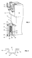
- an electrical switch device comprises a housing 10 of approximately parallelepiped shape having a rear wall 12 with a notch 13 intended to receive a mounting support 5 itself fixed for example in a box, a cabinet or a frame.
- the mounting support 5 is a substantially horizontal DIN rail
- the cross section has a known hat shape with two opposite edges.
- the notch 13 has on its upper part a beak or a jaw 11 in which is housed on the upper edge of the rail 5, so as to place the device on the rail mounting 5.
- the locking device comprises a lock 40 of elongated shape which slides in translation along a vertical axis and which has at its upper end a nose 41.
- the locking device has two stable positions: one position unlocked in which the nose 41 of the lock 40 disappears from the rail (FIG. 3) and a locked position in which the nose 41 of the lock 40 jams the lower edge of the mounting rail 5 against the switch device thus allowing it to be locked (figure 2).
- the latch 40 is composed of a part median 44 vertical surrounded by two lateral parts 46 approximately perpendicular to the middle portion 44.
- the side portions 46 are themselves extended on each side towards the outside by vertical walls forming runners 43 parallel to the middle part 44.
- the nose of the lock 40 is composed, for example, of two tabs transverse 41 located in the extension of the lateral parts 46 and having each an oblique face which engages with the lower edge of the mounting rail 5 (see figure 2) to wedge it. Between the two tabs of the nose 41, the middle part 44 of the lock 40 is further extended by a substantially horizontal face 42.
- the vertical slides 43 allow the lock 40 to slide in corresponding vertical grooves 17 arranged in the rear face 12 of the housing 10, below the notch 13, thus authorizing the displacement of the lock only along the vertical axis.
- the lock 40 does not require any elastic part which would serve to facilitate its maintenance in a given position, by example by snap or other. It is then simple in design and easily achievable in a rigid material such as metal, more resistant than plastic. His only degree of freedom from the device is a vertical movement framed by the interlocking of the slides 43 in the corresponding grooves 17. It is therefore strong enough and well suited to hold against a mounting rail electrical appliances including heavy gauge.
- the central part 44 of the latch 40 has an orifice 49 close to its lower end and capable in particular of receiving a tool allowing a operator to easily pull the latch down to put it in position unlocked.
- the locking device also comprises a pawl 30 composed of a main arm 31 substantially perpendicular to a secondary arm 32 thus forming an inverted L-shaped cross section.
- the pawl 30 can pivot according to a horizontal tilting axis materialized by two teeth 34 extending outwards, on each side of the main arm 31. These teeth 34 rest in housings adapted (not shown) arranged on the rear face 12 of the device.
- the pawl 30 can thus swing around this axis 34 between a stable position said moved back (corresponding to the locked position of the device - Figure 2) and a stable position called advanced (corresponding to the unlocked position of the device - figure 3).
- the pawl comprises retaining means 35 which cooperate with complementary means 45 arranged on the latch 40 making it possible to maintain the device in unlocked position.
- these means of retainers consist of two pins 35 projecting from the main arm 31 in the same direction as the secondary arm 32 and placed on either side of the arm secondary 32.
- the pins 35 are introduced in two corresponding hooking notches 45, such as holes arranged in the slides 43 of the lock.
- the notches 45 are positioned on the slides 43 at a height such that, when the lugs 35 are inserted therein, the latch 40 is in unlocked position and is held by the pawl 30.
- the bottom of the main arm 31 of the pawl 30 rests against an inclined plane 15 arranged for this purpose in the rear face 12 of the device.
- Plane 15 is slightly inclined downwards and is located below the axis 34.
- the movement of the pawl 30 around the pivot axis 34 is therefore limited between these two inclined planes 14.15.
- the advanced position is obtained from that the pins 35 can be inserted into the hooking notches 45.
- the pawl 30 can be easily made of molded plastic for example since it does not act directly on the mounting rail 5 and therefore does not directly support the efforts to keep the device on the rail. However, it can also be metallic.
- the middle part 44 and the two lateral parts 46 of the latch 40 form between them a space 47 (see FIG. 4) used to install elastic means 20 which exert a force along the vertical axis of movement of the latch 40.
- these elastic means are constituted by one or more springs ordinary and therefore economical helical compression.
- the mode of embodiment presented comprises a single compression spring 20, but one could consider equivalently several compression springs in space 47.
- the compression spring 20 placed in the space 47, bears on a first of its ends 21 against the face 42 of the latch 40 and at a second opposite end 22 against the secondary arm 32 of the pawl 30. Like the pawl 30 can only pivot along the horizontal tilting axis 34, the vertical pressure force generated by the spring 20 therefore acts mainly on the latch 40.
- the operation of the locking device is as follows:
- the pawl 30 When the device is in the locked position ( Figure 2), the pawl 30 is locked in the retracted position against the inclined plane 14 by the ends of the lugs 35 which rest against the runners 43, but which do not prevent the lock from moving.
- the secondary arm 32 of the pawl serves as a base for the lower end 22 of the spring 20.
- the other end 21 of the spring presses on the face 42 and drives the latch 40 towards the high until the teeth 41 wedge the rail 5.
- a stop 16 is arranged on the rear face 12 of the device and against which the face 42 of the lock abuts so as to limit the stroke of the spring 20.
- an operator can introduce a tool into the orifice 49 and pull the latch 40 downwards.
- the pawl 30 will tilt in position advanced under the effect of the spring 20 which presses on the secondary arm 32 and the pins 35 will be introduced into the hooking notches 45, thus blocking the latch 40 and stabilizing the unlocked position of the locking device.
- this advanced position of the pawl is stable because the device according to the invention is designed so that, relative to the pivot axis 34, the moment of the pressure force of the spring 20 exerted downwards on the secondary arm 32 or higher at the time of the spring pressure force 20 exerted upwards on the notches 45 of the lock 40.
- This is due to the fact that the distance d1 (see FIG. 3) between the axis tilt 34 and the center of the secondary arm 32 (considered to be the point spring support) is greater than the distance d2 between the pivot axis 34 and the point of support of the notches 45 on the lugs 35. Consequently, apart from any external intervention, the pawl 30 is naturally pushed against the inclined plane 15 and therefore stabilized in the forward position.
- the main arm 31 of the pawl 30 extends beyond the underside of the apparatus so as to form a tongue 39 which can be actuated from the front of the device.
- an operator simply push this tab 39 backwards by a frontal action, this which has the effect of releasing the pins 35 from their notches 45.
- the lock 40 is then released and driven upwards by the action of the spring 20 towards the locked position and the pawl 30 switches to stable position retracted.
- the effort to provide on this tab 39 to release the pins 35 is a function of the distance between the tilting axis 34 and the push point on the tongue 39.
- the dimensions of the pawl 30 are obviously designed to be able to tilt it with a reasonable pushing force on the tab 39.
- the invention also relates to an electrical switch device having of such a locking device.
- certain devices additionally have several fixing holes 18,19 (see FIG. 1) intended to be able to fix them, for example using screws, on another type of mounting support, such as a mounting plate.
- the same device can advantageously be mounted either on a plate-type support or on a rail-type support, depending on the application desired by the user.
- the invention provides an economical solution consisting in that the orifice 49 of the central part 44 of the lock 40, used initially to pull the lock into position unlocked, has a suitable shape so that it can also be used as one of the fixing holes.
- the example in Figure 1 thus shows a device which could also be fixed on a mounting plate by means of two fixing holes 18,19 retractable positioned near the top corners of the device and through the hole 49 of the latch 40 in the lower middle part of the device.
Landscapes
- Engineering & Computer Science (AREA)
- Power Engineering (AREA)
- Switch Cases, Indication, And Locking (AREA)
- Train Traffic Observation, Control, And Security (AREA)
Applications Claiming Priority (2)
| Application Number | Priority Date | Filing Date | Title |
|---|---|---|---|
| FR0303973A FR2853147B1 (fr) | 2003-03-27 | 2003-03-27 | Dispositif de verrouillage bistable pour appareil electrique interrupteur |
| FR0303973 | 2003-03-27 |
Publications (2)
| Publication Number | Publication Date |
|---|---|
| EP1463166A1 true EP1463166A1 (de) | 2004-09-29 |
| EP1463166B1 EP1463166B1 (de) | 2015-10-14 |
Family
ID=32799785
Family Applications (1)
| Application Number | Title | Priority Date | Filing Date |
|---|---|---|---|
| EP04101255.0A Expired - Lifetime EP1463166B1 (de) | 2003-03-27 | 2004-03-26 | Bistabile Verriegelungsvorrichtung für ein elektrisches Gerät |
Country Status (4)
| Country | Link |
|---|---|
| EP (1) | EP1463166B1 (de) |
| CN (1) | CN1534842B (de) |
| ES (1) | ES2553603T3 (de) |
| FR (1) | FR2853147B1 (de) |
Cited By (2)
| Publication number | Priority date | Publication date | Assignee | Title |
|---|---|---|---|---|
| FR2967833A1 (fr) * | 2010-11-23 | 2012-05-25 | Legrand France | Appareil electrique a fixation reversible, demontable sans outil |
| US20130216304A1 (en) * | 2010-08-20 | 2013-08-22 | Ralf Schumacher | Mounting rail and module latching system |
Families Citing this family (3)
| Publication number | Priority date | Publication date | Assignee | Title |
|---|---|---|---|---|
| CN104466694B (zh) * | 2014-11-20 | 2017-05-24 | 河南耐博电气科技有限公司 | 一种配电箱内开关的安装装置 |
| FR3058004B1 (fr) * | 2016-10-24 | 2021-10-22 | Mersen France Sb Sas | Appareil electrique comprenant un dispositif de verrouillage pour verrouiller cet appareil electrique sur un rail de fixation |
| EP3376617B1 (de) * | 2017-03-14 | 2019-01-09 | Sick AG | Befestigungsvorrichtung |
Citations (3)
| Publication number | Priority date | Publication date | Assignee | Title |
|---|---|---|---|---|
| DE2337351A1 (de) * | 1973-07-23 | 1975-02-06 | Siemens Ag | Elektrisches geraet |
| DE3922551A1 (de) * | 1989-07-08 | 1991-01-17 | Geyer Gmbh & Co Christian | Vorrichtung zur befestigung eines elektrischen schaltgeraetes |
| DE4107075A1 (de) * | 1990-03-15 | 1991-09-19 | Abb Patent Gmbh | Schnappbefestigung fuer ein elektrisches installationsgeraet auf einer hutprofiltragschiene |
Family Cites Families (1)
| Publication number | Priority date | Publication date | Assignee | Title |
|---|---|---|---|---|
| JP2001327009A (ja) * | 2000-05-15 | 2001-11-22 | Kawamura Electric Inc | 分電盤のブレーカ取付構造 |
-
2003
- 2003-03-27 FR FR0303973A patent/FR2853147B1/fr not_active Expired - Lifetime
-
2004
- 2004-03-26 EP EP04101255.0A patent/EP1463166B1/de not_active Expired - Lifetime
- 2004-03-26 ES ES04101255.0T patent/ES2553603T3/es not_active Expired - Lifetime
- 2004-03-29 CN CN2004100430909A patent/CN1534842B/zh not_active Expired - Lifetime
Patent Citations (3)
| Publication number | Priority date | Publication date | Assignee | Title |
|---|---|---|---|---|
| DE2337351A1 (de) * | 1973-07-23 | 1975-02-06 | Siemens Ag | Elektrisches geraet |
| DE3922551A1 (de) * | 1989-07-08 | 1991-01-17 | Geyer Gmbh & Co Christian | Vorrichtung zur befestigung eines elektrischen schaltgeraetes |
| DE4107075A1 (de) * | 1990-03-15 | 1991-09-19 | Abb Patent Gmbh | Schnappbefestigung fuer ein elektrisches installationsgeraet auf einer hutprofiltragschiene |
Cited By (3)
| Publication number | Priority date | Publication date | Assignee | Title |
|---|---|---|---|---|
| US20130216304A1 (en) * | 2010-08-20 | 2013-08-22 | Ralf Schumacher | Mounting rail and module latching system |
| US9263861B2 (en) * | 2010-08-20 | 2016-02-16 | Weidmueller Interface Gmbh & Co. Kg | Mounting rail and module latching system |
| FR2967833A1 (fr) * | 2010-11-23 | 2012-05-25 | Legrand France | Appareil electrique a fixation reversible, demontable sans outil |
Also Published As
| Publication number | Publication date |
|---|---|
| FR2853147B1 (fr) | 2005-05-06 |
| CN1534842B (zh) | 2010-04-28 |
| CN1534842A (zh) | 2004-10-06 |
| EP1463166B1 (de) | 2015-10-14 |
| FR2853147A1 (fr) | 2004-10-01 |
| ES2553603T3 (es) | 2015-12-10 |
Similar Documents
| Publication | Publication Date | Title |
|---|---|---|
| EP2458607B1 (de) | Verriegelungsvorrichtung zur Sicherung des Zugangs zur Kabeldose einer Stromzelle, und Stromzelle, die eine solche Vorrichtung enthält | |
| EP2059985A1 (de) | Installationsmechanismus zur anbringung hinter einer installationshalterung und elektrische geräte mit einem solchen mechanismus | |
| FR2723667A1 (fr) | Dispositif pour l'extraction d'un ensemble enfichable | |
| EP1463166B1 (de) | Bistabile Verriegelungsvorrichtung für ein elektrisches Gerät | |
| EP0785606B1 (de) | Vorrichtung zum Befestigen eines elektrischen Gerätes | |
| FR2967829A1 (fr) | Prise electrique comportant des montants lateraux mobiles en translation | |
| EP2369698A1 (de) | Schienenauflagerung zur Montage von elektrischen Geräten in einem elektrischen Schaltkasten | |
| EP3813089B1 (de) | Elektrischer minischalter vom typ normalerweise geschlossen, mit einer verriegelungsposition des offenem kontaktes | |
| EP0683350A1 (de) | Vorrichtung zum Befestigen von Kameras auf einem Dreibeinstativ | |
| FR2553247A3 (fr) | Telephone, en particulier telephone pour automobile, equipe d'un dispositif de verrouillage perfectionne | |
| EP0651483B1 (de) | Schnellbefestigungsvorrichtung für einem Träger in einem Schaltschrank | |
| EP2369699B1 (de) | Elektrischer Verteiler- oder Schaltkasten, der eine entfernbare Schienenauflagerung für die Montage von elektrischen Geräten umfasst | |
| FR2564887A1 (fr) | Dispositif auxiliaire de verrouillage pour tiroir de coffret de rangement et tiroir destine a recevoir ce dispositif. | |
| FR2877138A1 (fr) | Sectionneur a fusibles | |
| BE1024155B1 (fr) | Systeme pour le montage d'un cadre de support pour appareils electriques modulaires | |
| WO2023209147A1 (fr) | Dispositif de positionnement d'un châssis d'armoire électrique, et armoire électrique associée | |
| BE1009657A3 (fr) | Interrupteur modulaire a coulisseau reversible. | |
| EP2613337B1 (de) | Zusammenbau eines elektrischen Geräts zum Schutz von Stromleitungen, das aus zwei Blöcken besteht | |
| FR3028103A3 (fr) | Tableau de distribution d'energie electrique avec traverse d'assemblage inclinable pour le support d'unites electriques modulaires | |
| FR2708390A1 (fr) | Dispositif de fixation d'un appareil électrique sur un profilé de support. | |
| CH716357B1 (fr) | Appareil modulaire électrique muni d'un élément de blocage. | |
| FR3102106A1 (fr) | Dispositif de fixation d’une assise de banquette sur un chassis de vehicule automobile | |
| FR2662298A1 (fr) | Assemblage a verrouillage compact pour disjoncteur a boitier moule. | |
| FR2952274A1 (fr) | Dispositif de montage d'un montant de chassis sur le fond d'un coffret electrique et coffret electrique comprenant un tel dispositif | |
| FR2952275A1 (fr) | Dispositif de montage d'un montant de chassis sur le fond d'un coffret electrique et coffret electrique comprenant un tel dispositif |
Legal Events
| Date | Code | Title | Description |
|---|---|---|---|
| PUAI | Public reference made under article 153(3) epc to a published international application that has entered the european phase |
Free format text: ORIGINAL CODE: 0009012 |
|
| AK | Designated contracting states |
Kind code of ref document: A1 Designated state(s): AT BE BG CH CY CZ DE DK EE ES FI FR GB GR HU IE IT LI LU MC NL PL PT RO SE SI SK TR |
|
| AX | Request for extension of the european patent |
Extension state: AL LT LV MK |
|
| 17P | Request for examination filed |
Effective date: 20041020 |
|
| AKX | Designation fees paid |
Designated state(s): DE ES GB IT |
|
| RAP1 | Party data changed (applicant data changed or rights of an application transferred) |
Owner name: SCHNEIDER ELECTRIC INDUSTRIES SAS |
|
| GRAP | Despatch of communication of intention to grant a patent |
Free format text: ORIGINAL CODE: EPIDOSNIGR1 |
|
| INTG | Intention to grant announced |
Effective date: 20150806 |
|
| GRAS | Grant fee paid |
Free format text: ORIGINAL CODE: EPIDOSNIGR3 |
|
| GRAA | (expected) grant |
Free format text: ORIGINAL CODE: 0009210 |
|
| AK | Designated contracting states |
Kind code of ref document: B1 Designated state(s): DE ES GB IT |
|
| REG | Reference to a national code |
Ref country code: GB Ref legal event code: FG4D Free format text: NOT ENGLISH |
|
| REG | Reference to a national code |
Ref country code: DE Ref legal event code: R096 Ref document number: 602004048052 Country of ref document: DE |
|
| REG | Reference to a national code |
Ref country code: ES Ref legal event code: FG2A Ref document number: 2553603 Country of ref document: ES Kind code of ref document: T3 Effective date: 20151210 |
|
| REG | Reference to a national code |
Ref country code: DE Ref legal event code: R097 Ref document number: 602004048052 Country of ref document: DE |
|
| PLBE | No opposition filed within time limit |
Free format text: ORIGINAL CODE: 0009261 |
|
| STAA | Information on the status of an ep patent application or granted ep patent |
Free format text: STATUS: NO OPPOSITION FILED WITHIN TIME LIMIT |
|
| 26N | No opposition filed |
Effective date: 20160715 |
|
| PGFP | Annual fee paid to national office [announced via postgrant information from national office to epo] |
Ref country code: IT Payment date: 20230321 Year of fee payment: 20 Ref country code: GB Payment date: 20230321 Year of fee payment: 20 Ref country code: DE Payment date: 20230328 Year of fee payment: 20 |
|
| PGFP | Annual fee paid to national office [announced via postgrant information from national office to epo] |
Ref country code: ES Payment date: 20230424 Year of fee payment: 20 |
|
| REG | Reference to a national code |
Ref country code: DE Ref legal event code: R071 Ref document number: 602004048052 Country of ref document: DE |
|
| REG | Reference to a national code |
Ref country code: ES Ref legal event code: FD2A Effective date: 20240404 |
|
| PG25 | Lapsed in a contracting state [announced via postgrant information from national office to epo] |
Ref country code: ES Free format text: LAPSE BECAUSE OF EXPIRATION OF PROTECTION Effective date: 20240327 |
|
| REG | Reference to a national code |
Ref country code: GB Ref legal event code: PE20 Expiry date: 20240325 |
|
| PG25 | Lapsed in a contracting state [announced via postgrant information from national office to epo] |
Ref country code: ES Free format text: LAPSE BECAUSE OF EXPIRATION OF PROTECTION Effective date: 20240327 Ref country code: GB Free format text: LAPSE BECAUSE OF EXPIRATION OF PROTECTION Effective date: 20240325 |