EP1463166A1 - Bistable locking device for an electrical switching device - Google Patents
Bistable locking device for an electrical switching device Download PDFInfo
- Publication number
- EP1463166A1 EP1463166A1 EP04101255A EP04101255A EP1463166A1 EP 1463166 A1 EP1463166 A1 EP 1463166A1 EP 04101255 A EP04101255 A EP 04101255A EP 04101255 A EP04101255 A EP 04101255A EP 1463166 A1 EP1463166 A1 EP 1463166A1
- Authority
- EP
- European Patent Office
- Prior art keywords
- pawl
- locking device
- lock
- latch
- unlocked position
- Prior art date
- Legal status (The legal status is an assumption and is not a legal conclusion. Google has not performed a legal analysis and makes no representation as to the accuracy of the status listed.)
- Granted
Links
- 230000006835 compression Effects 0.000 claims abstract description 6
- 238000007906 compression Methods 0.000 claims abstract description 6
- 230000000295 complement effect Effects 0.000 claims abstract description 4
- 239000000463 material Substances 0.000 claims description 3
- 239000004033 plastic Substances 0.000 claims description 2
- 239000007769 metal material Substances 0.000 claims 1
- 230000000694 effects Effects 0.000 description 3
- 230000006978 adaptation Effects 0.000 description 1
- 210000003323 beak Anatomy 0.000 description 1
- 230000000903 blocking effect Effects 0.000 description 1
- 238000010586 diagram Methods 0.000 description 1
- 238000006073 displacement reaction Methods 0.000 description 1
- 238000012423 maintenance Methods 0.000 description 1
- 239000002184 metal Substances 0.000 description 1
- 239000002991 molded plastic Substances 0.000 description 1
- 230000000087 stabilizing effect Effects 0.000 description 1
- 230000002459 sustained effect Effects 0.000 description 1
Images

Classifications
-
- H—ELECTRICITY
- H02—GENERATION; CONVERSION OR DISTRIBUTION OF ELECTRIC POWER
- H02B—BOARDS, SUBSTATIONS OR SWITCHING ARRANGEMENTS FOR THE SUPPLY OR DISTRIBUTION OF ELECTRIC POWER
- H02B1/00—Frameworks, boards, panels, desks, casings; Details of substations or switching arrangements
- H02B1/015—Boards, panels, desks; Parts thereof or accessories therefor
- H02B1/04—Mounting thereon of switches or of other devices in general, the switch or device having, or being without, casing
- H02B1/052—Mounting on rails
- H02B1/0523—Mounting on rails locked into position by a sliding member
Definitions
- the present invention relates to a bistable locking device for quickly hanging an electrical low-voltage switch device, particular a contactor, a circuit breaker, a contactor-breaker or other, on a mounting bracket.
- the invention also relates to an apparatus comprising such a device.
- electrical switch devices include generally on their rear side a hanging system intended to be able to fix them on a mounting bracket, especially inside a box or cabinet.
- a hanging system intended to be able to fix them on a mounting bracket, especially inside a box or cabinet.
- Such system is often used to allow the device to be hung on a rail profile fixing, such as a horizontal DIN rail, of hat-shaped section having two opposite edges and whose section dimensions are standard.
- a rail profile fixing such as a horizontal DIN rail
- this system presents the advantage of being more flexible and faster so that the assembly of the devices is more easily implemented by a user. Once hung, it's easy to electrically connect the devices.
- the attachment system of a switch device comprises a notch or a hooking jaw arranged over all or part of the width from the rear of the device and which allows the upper edge of the rail to be wedged.
- the hanging system also has a latch which can trap the lower edge of the rail so that the device can be locked against the rail.
- This lock is removable manually or automatically by elastic means between a withdrawn position, in which it releases the rail (unlocked position) and a position locked, in which it immobilizes the device by pinching the lower edge of the rail against the device (locked position).
- an operator first hooks the jaw of the device against the upper edge of the rail then activates the elastic means of the system attachment, for example using a tool or directly by an inclined plane, to ability to freely position the device against the bottom edge of the rail. Once the device well positioned, the elastic means are released so as to lock the device completely against the rail.
- bistable system benefiting from a locked position and from a stable unlocked position
- high-caliber switchgear such as for example low voltage protection and / or control for 100 kW motors or plus, the weight of which can make it difficult to mount and precisely position it.
- the invention describes a device for locking an electrical appliance switch on a mounting support, comprising a movable lock in translation along a vertical axis between a stable unlocked position in which the device is unlocked from the mounting bracket and a stable locked position in which the device is locked by the lock against the mounting bracket.
- the device comprises a pawl capable of pivoting along a substantially tilting axis perpendicular to the axis of translation and provided with retaining means which cooperate with complementary means arranged on the lock to keep the device in unlocked position.
- the device also includes elastic means intended to keep the device in the locked position and of which a first end presses against the latch and a second opposite end presses against the pawl.
- the pawl comprises an actuatable tongue from the front of the switch device, allowing the ratchet to tilt and switch the device to the locked position. So the locking action of the device is extremely simple since it consists simply in actuating this tab of the ratchet from the front of the device.
- the lock has an orifice allowing the device to be placed in the unlocked position, for example at using a tool.
- the latch, the pawl and the elastic means are separate parts which can therefore be easily made from different materials adapted to each other's efforts.
- the lock can only slide along a vertical axis. Unlike other solutions, it does not need to snap or hang on by making any movement in a another direction, since it is a separate ratchet that pivots to hold the latch in unlocked position. This characteristic makes it possible to significantly improve the rigidity of the lock and therefore keeping the device in the locked position.
- an electrical switch device comprises a housing 10 of approximately parallelepiped shape having a rear wall 12 with a notch 13 intended to receive a mounting support 5 itself fixed for example in a box, a cabinet or a frame.
- the mounting support 5 is a substantially horizontal DIN rail
- the cross section has a known hat shape with two opposite edges.
- the notch 13 has on its upper part a beak or a jaw 11 in which is housed on the upper edge of the rail 5, so as to place the device on the rail mounting 5.
- the locking device comprises a lock 40 of elongated shape which slides in translation along a vertical axis and which has at its upper end a nose 41.
- the locking device has two stable positions: one position unlocked in which the nose 41 of the lock 40 disappears from the rail (FIG. 3) and a locked position in which the nose 41 of the lock 40 jams the lower edge of the mounting rail 5 against the switch device thus allowing it to be locked (figure 2).
- the latch 40 is composed of a part median 44 vertical surrounded by two lateral parts 46 approximately perpendicular to the middle portion 44.
- the side portions 46 are themselves extended on each side towards the outside by vertical walls forming runners 43 parallel to the middle part 44.
- the nose of the lock 40 is composed, for example, of two tabs transverse 41 located in the extension of the lateral parts 46 and having each an oblique face which engages with the lower edge of the mounting rail 5 (see figure 2) to wedge it. Between the two tabs of the nose 41, the middle part 44 of the lock 40 is further extended by a substantially horizontal face 42.
- the vertical slides 43 allow the lock 40 to slide in corresponding vertical grooves 17 arranged in the rear face 12 of the housing 10, below the notch 13, thus authorizing the displacement of the lock only along the vertical axis.
- the lock 40 does not require any elastic part which would serve to facilitate its maintenance in a given position, by example by snap or other. It is then simple in design and easily achievable in a rigid material such as metal, more resistant than plastic. His only degree of freedom from the device is a vertical movement framed by the interlocking of the slides 43 in the corresponding grooves 17. It is therefore strong enough and well suited to hold against a mounting rail electrical appliances including heavy gauge.
- the central part 44 of the latch 40 has an orifice 49 close to its lower end and capable in particular of receiving a tool allowing a operator to easily pull the latch down to put it in position unlocked.
- the locking device also comprises a pawl 30 composed of a main arm 31 substantially perpendicular to a secondary arm 32 thus forming an inverted L-shaped cross section.
- the pawl 30 can pivot according to a horizontal tilting axis materialized by two teeth 34 extending outwards, on each side of the main arm 31. These teeth 34 rest in housings adapted (not shown) arranged on the rear face 12 of the device.
- the pawl 30 can thus swing around this axis 34 between a stable position said moved back (corresponding to the locked position of the device - Figure 2) and a stable position called advanced (corresponding to the unlocked position of the device - figure 3).
- the pawl comprises retaining means 35 which cooperate with complementary means 45 arranged on the latch 40 making it possible to maintain the device in unlocked position.
- these means of retainers consist of two pins 35 projecting from the main arm 31 in the same direction as the secondary arm 32 and placed on either side of the arm secondary 32.
- the pins 35 are introduced in two corresponding hooking notches 45, such as holes arranged in the slides 43 of the lock.
- the notches 45 are positioned on the slides 43 at a height such that, when the lugs 35 are inserted therein, the latch 40 is in unlocked position and is held by the pawl 30.
- the bottom of the main arm 31 of the pawl 30 rests against an inclined plane 15 arranged for this purpose in the rear face 12 of the device.
- Plane 15 is slightly inclined downwards and is located below the axis 34.
- the movement of the pawl 30 around the pivot axis 34 is therefore limited between these two inclined planes 14.15.
- the advanced position is obtained from that the pins 35 can be inserted into the hooking notches 45.
- the pawl 30 can be easily made of molded plastic for example since it does not act directly on the mounting rail 5 and therefore does not directly support the efforts to keep the device on the rail. However, it can also be metallic.
- the middle part 44 and the two lateral parts 46 of the latch 40 form between them a space 47 (see FIG. 4) used to install elastic means 20 which exert a force along the vertical axis of movement of the latch 40.
- these elastic means are constituted by one or more springs ordinary and therefore economical helical compression.
- the mode of embodiment presented comprises a single compression spring 20, but one could consider equivalently several compression springs in space 47.
- the compression spring 20 placed in the space 47, bears on a first of its ends 21 against the face 42 of the latch 40 and at a second opposite end 22 against the secondary arm 32 of the pawl 30. Like the pawl 30 can only pivot along the horizontal tilting axis 34, the vertical pressure force generated by the spring 20 therefore acts mainly on the latch 40.
- the operation of the locking device is as follows:
- the pawl 30 When the device is in the locked position ( Figure 2), the pawl 30 is locked in the retracted position against the inclined plane 14 by the ends of the lugs 35 which rest against the runners 43, but which do not prevent the lock from moving.
- the secondary arm 32 of the pawl serves as a base for the lower end 22 of the spring 20.
- the other end 21 of the spring presses on the face 42 and drives the latch 40 towards the high until the teeth 41 wedge the rail 5.
- a stop 16 is arranged on the rear face 12 of the device and against which the face 42 of the lock abuts so as to limit the stroke of the spring 20.
- an operator can introduce a tool into the orifice 49 and pull the latch 40 downwards.
- the pawl 30 will tilt in position advanced under the effect of the spring 20 which presses on the secondary arm 32 and the pins 35 will be introduced into the hooking notches 45, thus blocking the latch 40 and stabilizing the unlocked position of the locking device.
- this advanced position of the pawl is stable because the device according to the invention is designed so that, relative to the pivot axis 34, the moment of the pressure force of the spring 20 exerted downwards on the secondary arm 32 or higher at the time of the spring pressure force 20 exerted upwards on the notches 45 of the lock 40.
- This is due to the fact that the distance d1 (see FIG. 3) between the axis tilt 34 and the center of the secondary arm 32 (considered to be the point spring support) is greater than the distance d2 between the pivot axis 34 and the point of support of the notches 45 on the lugs 35. Consequently, apart from any external intervention, the pawl 30 is naturally pushed against the inclined plane 15 and therefore stabilized in the forward position.
- the main arm 31 of the pawl 30 extends beyond the underside of the apparatus so as to form a tongue 39 which can be actuated from the front of the device.
- an operator simply push this tab 39 backwards by a frontal action, this which has the effect of releasing the pins 35 from their notches 45.
- the lock 40 is then released and driven upwards by the action of the spring 20 towards the locked position and the pawl 30 switches to stable position retracted.
- the effort to provide on this tab 39 to release the pins 35 is a function of the distance between the tilting axis 34 and the push point on the tongue 39.
- the dimensions of the pawl 30 are obviously designed to be able to tilt it with a reasonable pushing force on the tab 39.
- the invention also relates to an electrical switch device having of such a locking device.
- certain devices additionally have several fixing holes 18,19 (see FIG. 1) intended to be able to fix them, for example using screws, on another type of mounting support, such as a mounting plate.
- the same device can advantageously be mounted either on a plate-type support or on a rail-type support, depending on the application desired by the user.
- the invention provides an economical solution consisting in that the orifice 49 of the central part 44 of the lock 40, used initially to pull the lock into position unlocked, has a suitable shape so that it can also be used as one of the fixing holes.
- the example in Figure 1 thus shows a device which could also be fixed on a mounting plate by means of two fixing holes 18,19 retractable positioned near the top corners of the device and through the hole 49 of the latch 40 in the lower middle part of the device.
Abstract
Description
La présente invention se rapporte à un dispositif de verrouillage bistable permettant d'accrocher rapidement un appareil électrique interrupteur basse tension, en particulier un contacteur, un disjoncteur, un contacteur-disjoncteur ou autre, sur un support de montage. L'invention concerne également un appareil comportant un tel dispositif.The present invention relates to a bistable locking device for quickly hanging an electrical low-voltage switch device, particular a contactor, a circuit breaker, a contactor-breaker or other, on a mounting bracket. The invention also relates to an apparatus comprising such a device.
Il est connu que les appareils électriques interrupteurs comportent généralement sur leur face arrière un système d'accrochage destiné à pouvoir les fixer sur un support de montage, notamment àl'intérieur d'un coffret ou d'une armoire. Un tel système est souvent utilisé pour permettre un accrochage de l'appareil sur un rail de fixation profilé, tel qu'un rail DIN horizontal, de section en forme de chapeau présentant deux bords opposés et dont les dimensions de la section sont standards. Par rapport à un accrochage classique sur une platine àl'aide de vis de fixation, ce système présente l'avantage d'être plus souple et plus rapide de sorte que le montage des appareils est plus facilement mis en oeuvre par un utilisateur. Une fois accrochés, il est facile de raccorder électriquement les appareils.It is known that electrical switch devices include generally on their rear side a hanging system intended to be able to fix them on a mounting bracket, especially inside a box or cabinet. Such system is often used to allow the device to be hung on a rail profile fixing, such as a horizontal DIN rail, of hat-shaped section having two opposite edges and whose section dimensions are standard. Compared to a classic hooking on a plate using fixing screws, this system presents the advantage of being more flexible and faster so that the assembly of the devices is more easily implemented by a user. Once hung, it's easy to electrically connect the devices.
Habituellement, le système d'accrochage d'un appareil interrupteur comporte une encoche ou une mâchoire d'accrochage disposée sur toute ou partie de la largeur de la face arrière de l'appareil et qui permet de coincer le bord supérieur du rail. Le système d'accrochage comporte également un verrou qui est susceptible de coincer le bord inférieur du rail de façon àpouvoir verrouiller l'appareil contre le rail. Ce verrou est amovible manuellement ou automatiquement grâce àdes moyens élastiques entre une position retirée, dans laquelle il libère le rail (position déverrouillée) et une position verrouillée, dans laquelle il immobilise l'appareil en venant pincer le bord inférieur du rail contre l'appareil (position verrouillée).Usually, the attachment system of a switch device comprises a notch or a hooking jaw arranged over all or part of the width from the rear of the device and which allows the upper edge of the rail to be wedged. The hanging system also has a latch which can trap the lower edge of the rail so that the device can be locked against the rail. This lock is removable manually or automatically by elastic means between a withdrawn position, in which it releases the rail (unlocked position) and a position locked, in which it immobilizes the device by pinching the lower edge of the rail against the device (locked position).
Pour fixer un appareil, un opérateur accroche d'abord la mâchoire de l'appareil contre le bord supérieur du rail puis actionne les moyens élastiques du système d'accrochage, par exemple à l'aide d'un outil ou directement par un plan incliné, pour pouvoir positionner librement l'appareil contre le bord inférieur du rail. Une fois l'appareil bien positionné, les moyens élastiques sont relâchés de manière à verrouiller complètement l'appareil contre le rail.To fix a device, an operator first hooks the jaw of the device against the upper edge of the rail then activates the elastic means of the system attachment, for example using a tool or directly by an inclined plane, to ability to freely position the device against the bottom edge of the rail. Once the device well positioned, the elastic means are released so as to lock the device completely against the rail.
Cependant, un tel système d'accrochage ne possède qu'une position stable, correspondant à la position verrouillée. L'autre position, correspondant à la position déverrouillée, ne peut être obtenue que par une action maintenue de l'opérateur sur les moyens élastiques.However, such a hanging system only has a stable position, corresponding to the locked position. The other position, corresponding to the position unlocked, can only be obtained by a sustained action of the operator on the elastic means.
On veut parfois conserver la possibilité de déplacer librement plusieurs appareils le long du rail, après avoir positionné leur mâchoire sur le bord supérieur, avant de les fixer définitivement. Cela permet entre autres de régler facilement leur position précise les uns par rapport aux autres. Dans ce cas, un opérateur avec un seul outil pourra rencontrer des difficultés à positionner deux appareils ou plus l'un par rapport à l'autre, en étant obligé de maintenir simultanément les deux systèmes d'accrochage en position déverrouillée. Il s'ensuit une perte de temps durant le montage des appareils.Sometimes we want to keep the possibility of freely moving several devices along the rail, after positioning their jaws on the upper edge, before finally fixing them. This allows, among other things, to easily adjust their precise position in relation to each other. In this case, an operator with only one tool may have difficulty positioning two or more devices, one by relation to the other, by being obliged to maintain both systems simultaneously hooking in unlocked position. This results in a loss of time during assembly machines.
Il est donc intéressant de disposer d'un système possédant deux positions stables de façon àce que l'appareil puisse être déplacé librement sur le rail sans l'aide d'un outil avant d'être verrouillé. De telles solutions existent déjà notamment dans les documents DE3513762, DE4003408, DE4011446, FR2666482, EP0978913, DE20216516. Néanmoins, les systèmes présentés dans ces documents sont souvent destinés à des appareils de faible poids ou encombrement, tels que des appareils modulaires, et ils ne sont pas forcément adaptés à supporter de gros appareils interrupteurs.It is therefore interesting to have a system with two positions stable so that the device can be moved freely on the rail without assistance a tool before being locked. Such solutions already exist in particular in documents DE3513762, DE4003408, DE4011446, FR2666482, EP0978913, DE20216516. However, the systems presented in these documents are often intended for devices of light weight or bulk, such as devices modular, and they are not necessarily suitable for supporting large devices switches.
Or, la présence d'un système bistable, bénéficiant d'une position verrouillée et d'une position déverrouillée stables, est encore plus intéressante dans le cas d'appareils interrupteurs de fort calibre, comme par exemple des appareils de protection et/ou de commande basse tension destinés à des moteurs de 100 kW ou plus, dont le poids peut rendre pénible le montage et le positionnement précis. De plus, on est parfois amené àfixer simultanément sur un même rail plusieurs gros appareils préalablement raccordés ensemble, en particulier dans le cas de deux contacteurs moteur précâblés en inverseurs. Il serait donc avantageux de concevoir un dispositif de verrouillage bistable économique et simple d'utilisation mais qui soit suffisamment fiable et robuste pour être capable de maintenir efficacement sur un rail tout appareil, en particulier des appareils de fort calibre.However, the presence of a bistable system, benefiting from a locked position and from a stable unlocked position, is even more interesting in the case high-caliber switchgear, such as for example low voltage protection and / or control for 100 kW motors or plus, the weight of which can make it difficult to mount and precisely position it. Moreover, sometimes we have to fix several large devices simultaneously on the same rail previously connected together, in particular in the case of two contactors motor pre-wired in reversers. It would therefore be advantageous to design a economical and easy to use, but sufficiently reliable bistable locking and robust to be able to efficiently hold any device on a rail, while especially heavy gauge devices.
Pour cela, l'invention décrit un dispositif de verrouillage d'un appareil électrique interrupteur sur un support de montage, comprenant un verrou mobile en translation selon un axe vertical entre une position déverrouillée stable dans laquelle l'appareil est déverrouillé du support de montage et une position verrouillée stable dans laquelle l'appareil est verrouillé par le verrou contre le support de montage. Le dispositif comporte un cliquet susceptible de pivoter selon un axe de basculement sensiblement perpendiculaire àl'axe de translation et muni de moyens de retenue qui coopèrent avec des moyens complémentaires agencés sur le verrou pour maintenir le dispositif en position déverrouillée. Le dispositif comporte également des moyens élastiques destinés à maintenir le dispositif en position verrouillée et dont une première extrémité prend appui contre le verrou et une seconde extrémité opposée prend appui contre le cliquet.For this, the invention describes a device for locking an electrical appliance switch on a mounting support, comprising a movable lock in translation along a vertical axis between a stable unlocked position in which the device is unlocked from the mounting bracket and a stable locked position in which the device is locked by the lock against the mounting bracket. The device comprises a pawl capable of pivoting along a substantially tilting axis perpendicular to the axis of translation and provided with retaining means which cooperate with complementary means arranged on the lock to keep the device in unlocked position. The device also includes elastic means intended to keep the device in the locked position and of which a first end presses against the latch and a second opposite end presses against the pawl.
Selon une caractéristique, le cliquet comporte une languette actionnable depuis l'avant de l'appareil interrupteur, permettant de faire basculer le cliquet et de passer le dispositif en position verrouillée. Ainsi, l'action de verrouillage de l'appareil est extrêmement simple puisqu'elle consiste simplement à actionner cette languette du cliquet àpartir de l'avant de l'appareil. Selon une autre caractéristique le verrou présente un orifice permettant de mettre le dispositif en position déverrouillée, par exemple à l'aide d'un outil.According to one characteristic, the pawl comprises an actuatable tongue from the front of the switch device, allowing the ratchet to tilt and switch the device to the locked position. So the locking action of the device is extremely simple since it consists simply in actuating this tab of the ratchet from the front of the device. According to another characteristic, the lock has an orifice allowing the device to be placed in the unlocked position, for example at using a tool.
Grâce à l'invention, le verrou, le cliquet et les moyens élastiques sont des pièces distinctes qui peuvent ainsi être fabriquées aisément avec différents matériaux adaptés aux efforts de chacune. De plus, le verrou ne peut uniquement que coulisser selon un axe vertical. Contrairement à d'autres solutions, il n'a pas besoin de s'encliqueter ou de s'accrocher en effectuant un quelconque mouvement dans une autre direction, puisque c'est un cliquet séparé qui pivote pour maintenir le verrou en position déverrouillée. Cette caractéristique permet d'améliorer notablement la rigidité du verrou et donc le maintien de l'appareil en position verrouillée.Thanks to the invention, the latch, the pawl and the elastic means are separate parts which can therefore be easily made from different materials adapted to each other's efforts. In addition, the lock can only slide along a vertical axis. Unlike other solutions, it does not need to snap or hang on by making any movement in a another direction, since it is a separate ratchet that pivots to hold the latch in unlocked position. This characteristic makes it possible to significantly improve the rigidity of the lock and therefore keeping the device in the locked position.
D'autres caractéristiques et avantages vont apparaítre dans la description détaillée qui suit en se référant à un mode de réalisation donné à titre d'exemple et représenté par les figures annexées sur lesquelles :
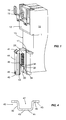
- la figure 1 représente un schéma simplifié d'une vue éclatée en perspective d'un appareil interrupteur muni d'un dispositif de verrouillage conforme àl'invention,
- les figures 2 et 3 montrent le dispositif de verrouillage en coupe transversale, selon un plan vertical avant-arrière, respectivement en position verrouillée et déverrouillée,
- la figure 4 schématise une coupe horizontale d'un exemple de verrou.
- FIG. 1 represents a simplified diagram of an exploded perspective view of a switch device provided with a locking device according to the invention,
- FIGS. 2 and 3 show the locking device in cross section, along a front-rear vertical plane, respectively in the locked and unlocked position,
- Figure 4 shows schematically a horizontal section of an example of a lock.
En référence aux figures, un appareil électrique interrupteur comporte un
boítier 10 de forme approximativement parallélépipédique présentant une paroi arrière
12 avec une échancrure 13 destinée àrecevoir un support de montage 5 lui-même fixé
par exemple dans un coffret, une armoire ou un châssis. Dans le mode de réalisation
représenté, le support de montage 5 est un rail DIN sensiblement horizontal dont la
section transversale a une forme connue de chapeau avec deux bords opposés.
L'échancrure 13 présente sur sa partie supérieure un bec ou une mâchoire 11 dans
laquelle vient se loger le bord supérieur du rail 5, de façon àposer l'appareil sur le rail de
montage 5. Une fois l'appareil posé, un opérateur peut encore le déplacer le long du rail
5 notamment pour le positionner précisément. Puis, pour fixer l'appareil, il suffit ensuite
de coincer le bord inférieur du rail 5 contre l'appareil à l'aide d'un dispositif de
verrouillage, objet de l'invention.With reference to the figures, an electrical switch device comprises a
Le dispositif de verrouillage comprend un verrou 40 de forme allongée qui
coulisse en translation selon un axe vertical et qui présente à son extrémité haute un
nez 41. Le dispositif de verrouillage comporte deux positions stables : une position
déverrouillée dans laquelle le nez 41 du verrou 40 s'efface du rail (figure 3) et une
position verrouillée dans laquelle le nez 41 du verrou 40 vient coincer le bord inférieur du
rail de montage 5 contre l'appareil interrupteur permettant ainsi de verrouiller celui-ci
(figure 2). En référence àl'exemple de la figure 4, le verrou 40 est composé d'une partie
médiane 44 verticale entourée de deux parties latérales 46 approximativement
perpendiculaires à la partie médiane 44. Les parties latérales 46 sont elles-mêmes
prolongées de chaque côté vers l'extérieur par des parois verticales formant des
glissières 43 parallèles àla partie médiane 44. The locking device comprises a
Le nez du verrou 40 est composé, par exemple, de deux languettes
transversales 41 situées dans le prolongement des parties latérales 46 et ayant
chacune une face oblique qui vient en prise avec le bord inférieur du rail de montage 5
(voir figure 2) pour le coincer. Entre les deux languettes du nez 41, la partie médiane 44
du verrou 40 est par ailleurs prolongée par une face 42 sensiblement horizontale.The nose of the
Les glissières verticales 43 permettent au verrou 40 de coulisser dans des
rainures verticales correspondantes 17 aménagées dans la face arrière 12 du boítier
10, au-dessous de l'échancrure 13, autorisant ainsi le déplacement du verrou
uniquement selon l'axe vertical. Avantageusement, le verrou 40 ne nécessite aucune
partie élastique qui servirait à faciliter son maintien dans une position donnée, par
exemple par encliquetage ou autre. Il est alors simple de conception et facilement
réalisable dans un matériau rigide tel que du métal, plus résistant que du plastique. Son
seul degré de liberté par rapport à l'appareil est un mouvement vertical encadré par
l'emboítement des glissières 43 dans les rainures correspondantes 17. Il est donc
suffisamment robuste et bien adapté pour maintenir contre un rail de montage des
appareils électriques y compris de fort calibre.The
Par ailleurs, la partie médiane 44 du verrou 40 possède un orifice 49 proche de
son extrémité basse et susceptible notamment de recevoir un outil permettant à un
opérateur de tirer aisément le verrou vers le bas afin de le mettre en position
déverrouillée.Furthermore, the
Le dispositif de verrouillage comporte également un cliquet 30 composé d'un
bras principal 31 sensiblement perpendiculaire à un bras secondaire 32 formant ainsi
une section transversale en forme de L renversé. Le cliquet 30 peut pivoter selon un
axe de basculement horizontal matérialisé par deux dents 34 s'étendant vers l'extérieur,
de chaque côté du bras principal 31. Ces dents 34 reposent dans des logements
adaptés (non schématisés) agencés sur la face arrière 12 de l'appareil.The locking device also comprises a
Le cliquet 30 peut ainsi basculer autour de cet axe 34 entre une position stable
dite reculée (correspondant à la position verrouillée du dispositif - figure 2) et une
position stable dite avancée (correspondant à la position déverrouillée du dispositif -
figure 3). Le cliquet comprend des moyens de retenue 35 qui coopèrent avec des
moyens complémentaires 45 agencés sur le verrou 40 permettant de maintenir le
dispositif en position déverrouillée. Dans le mode de réalisation préféré, ces moyens de
retenue sont constitués par deux ergots 35 débordant du bras principal 31 dans la
même direction que le bras secondaire 32 et placés de part et d'autre du bras
secondaire 32. Lorsque le cliquet est en position avancée, les ergots 35 s'introduisent
dans deux crans d'accrochage correspondants 45, tels que des trous agencés dans
les glissières 43 du verrou. Les crans 45 sont positionnés sur les glissières 43 à une
hauteur telle que, lorsque les ergots 35 sont insérés dedans, le verrou 40 se trouve en
position déverrouillée et est maintenu par le cliquet 30.The
Quand le verrou 40 n'est pas en position déverrouillée, les extrémités des
ergots 35 frottent contre les glissières 43, en dehors des crans 45, ce qui a pour effet
de maintenir le cliquet en position reculée. Dans cette position reculée, le haut du bras
principal 31 du cliquet 30 repose contre un plan incliné 14 aménagé àcet effet dans la
face arrière 12 de l'appareil. Ce plan 14 est légèrement incliné vers le haut et est situé
au-dessus de l'axe de basculement 34.When the
De même, en position avancée, le bas du bras principal 31 du cliquet 30
repose contre un plan incliné 15 aménagé à cet effet dans la face arrière 12 de
l'appareil. Le plan 15 est légèrement incliné vers le bas et est situé au-dessous de l'axe
de basculement 34. Le mouvement du cliquet 30 autour de l'axe de basculement 34 est
donc limité entre ces deux plans inclinés 14,15. La position avancée est obtenue dès
que les ergots 35 peuvent s'insérer dans les crans d'accrochage 45. Le cliquet 30 peut
être sans difficulté réalisé en matière plastique moulée par exemple puisqu'il n'agit pas
directement sur le rail de montage 5 et qu'il ne supporte donc pas directement les
efforts de maintien de l'appareil sur le rail. Néanmoins, il peut aussi être métallique.Similarly, in the advanced position, the bottom of the
La partie médiane 44 et les deux parties latérales 46 du verrou 40 forment
entre elles un espace 47 (voir figure 4) utilisé pour installer des moyens élastiques 20
qui exercent un effort selon l'axe vertical de déplacement du verrou 40.
Préférentiellement ces moyens élastiques sont constitués par un ou plusieurs ressorts
de compression hélicoïdaux 20 ordinaires et donc économiques. Le mode de
réalisation présenté comporte un seul ressort de compression 20, mais on pourrait
envisager de façon équivalente plusieurs ressorts de compression dans l'espace 47.The
Le ressort de compression 20, placé dans l'espace 47, prend appui à une
première de ses extrémités 21 contre la face 42 du verrou 40 et à une seconde
extrémité opposée 22 contre le bras secondaire 32 du cliquet 30. Comme le cliquet 30
ne peut que pivoter selon l'axe de basculement horizontal 34, l'effort de pression vertical
généré par le ressort 20 agit donc principalement sur le verrou 40. The
Ainsi, grâce à la solution décrite dans l'invention, on peut modifier l'effort de
pression que le dispositif de verrouillage doit exercer pour maintenir un appareil, sans
modifier le cliquet 30 ni le verrou 40, mais simplement en jouant sur le type et/ou le
nombre de ressorts 20. De cette façon, l'adaptation du dispositif àtoute une gamme
d'appareils plus ou moins lourds et encombrants devient extrêmement facile.Thus, thanks to the solution described in the invention, it is possible to modify the effort of
pressure that the locking device must exert to maintain a device, without
modify the
Le fonctionnement du dispositif de verrouillage est le suivant :The operation of the locking device is as follows:
Lorsque le dispositif est en position verrouillée (figure 2), le cliquet 30 est
bloqué en position reculée contre le plan incliné 14 par les extrémités des ergots 35 qui
reposent contre les glissières 43, mais qui n'empêchent pas le verrou de se déplacer.
Le bras secondaire 32 du cliquet sert de base pour l'extrémité basse 22 du ressort 20.
L'autre extrémité 21 du ressort appuie sur la face 42 et entraíne le verrou 40 vers le
haut jusqu'àce que les dents 41 coincent le rail 5. Dans le cas où le rail 5 ne serait pas
présent, une butée 16 est aménagée sur la face arrière 12 de l'appareil et contre
laquelle la face 42 du verrou vient buter de façon àlimiter la course du ressort 20.When the device is in the locked position (Figure 2), the
Pour passer de la position verrouillée à la position déverrouillée, un opérateur
peut introduire un outil dans l'orifice 49 et tirer le verrou 40 vers le bas. Au moment où
les ergots 35 vont venir en face des crans 45, le cliquet 30 va basculer en position
avancée sous l'effet du ressort 20 qui appuie sur le bras secondaire 32 et les ergots 35
vont s'introduire dans les crans d'accrochage 45, bloquant ainsi le verrou 40 et
stabilisant la position déverrouillée du dispositif de verrouillage.To switch from the locked position to the unlocked position, an operator
can introduce a tool into the
En effet, cette position avancée du cliquet est stable car le dispositif selon
l'invention est conçu pour que, par rapport àl'axe de basculement 34, le moment de la
force de pression du ressort 20 exercée vers le bas sur le bras secondaire 32 soit
supérieur au moment de la force de pression du ressort 20 exercée vers le haut sur les
crans 45 du verrou 40. Cela provient du fait que la distance d1 (voir figure 3) entre l'axe
de basculement 34 et le centre du bras secondaire 32 (considéré comme étant le point
d'appui du ressort) est supérieure à la distance d2 entre l'axe de basculement 34 et le
point d'appui des crans 45 sur les ergots 35. En conséquence, en dehors de toute
intervention extérieure, le cliquet 30 est naturellement poussé contre le plan incliné 15 et
donc stabilisé en position avancée.Indeed, this advanced position of the pawl is stable because the device according to
the invention is designed so that, relative to the
Le bras principal 31 du cliquet 30 se prolonge au-delàde la face inférieure de
l'appareil de façon à former une languette 39 qui est actionnable depuis l'avant de
l'appareil. Pour passer de la position déverrouillée àla position verrouillée, un opérateur
n'a simplement qu'à pousser cette languette 39 vers l'arrière par une action frontale, ce
qui a pour effet de libérer les ergots 35 de leurs crans 45. Le verrou 40 est alors libéré
et entraíné vers le haut sous l'action du ressort 20 vers la position verrouillée et le
cliquet 30 bascule en position stable reculée. L'effort à fournir sur cette languette 39
pour libérer les ergots 35 est fonction de la distance entre l'axe de basculement 34 et le
point de poussée sur la languette 39. Les dimensions du cliquet 30 sont évidemment
conçues pour pouvoir le basculer avec un effort de poussée raisonnable sur la
languette 39.The
L'invention concerne également un appareil électrique interrupteur disposant
d'un tel dispositif de verrouillage. Selon une caractéristique supplémentaire, certains
appareils comportent en plus plusieurs orifices de fixation 18,19 (voir figure 1) destinés
àpouvoir les fixer, par exemple àl'aide de vis, sur un autre type de support de montage,
tel qu'une platine de montage. Ainsi, un même appareil peut être avantageusement
monté soit sur un support de type platine, soit sur un support de type rail, en fonction de
l'application voulue par l'utilisateur. Pour limiter le nombre de pièces dans un tel
appareil, l'invention propose une solution économique consistant en ce que l'orifice 49
de la partie médiane 44 du verrou 40, servant initialement àtirer le verrou en position
déverrouillée, ait une forme adaptée pour pouvoir en plus être utilisée comme un des
orifices de fixation. L'exemple de la figure 1 montre ainsi un appareil qui pourrait aussi
être fixé sur une platine de montage au moyen de deux orifices de fixation 18,19
rétractables positionnés près des coins supérieurs de l'appareil et au moyen de l'orifice
49 du verrou 40 dans la partie médiane basse de l'appareil.The invention also relates to an electrical switch device having
of such a locking device. According to an additional characteristic, certain
devices additionally have several fixing
Il est bien entendu que l'on peut, sans sortir du cadre de l'invention, imaginer d'autres variantes et perfectionnements de détail et de même envisager l'emploi de moyens équivalents.It is understood that one can, without departing from the scope of the invention, imagine other variations and refinements of detail and likewise consider the use of equivalent means.
Claims (11)
Applications Claiming Priority (2)
| Application Number | Priority Date | Filing Date | Title |
|---|---|---|---|
| FR0303973A FR2853147B1 (en) | 2003-03-27 | 2003-03-27 | BISTABLE LOCKING DEVICE FOR ELECTRICAL DEVICE SWITCH |
| FR0303973 | 2003-03-27 |
Publications (2)
| Publication Number | Publication Date |
|---|---|
| EP1463166A1 true EP1463166A1 (en) | 2004-09-29 |
| EP1463166B1 EP1463166B1 (en) | 2015-10-14 |
Family
ID=32799785
Family Applications (1)
| Application Number | Title | Priority Date | Filing Date |
|---|---|---|---|
| EP04101255.0A Expired - Lifetime EP1463166B1 (en) | 2003-03-27 | 2004-03-26 | Bistable locking device for an electrical switching device |
Country Status (4)
| Country | Link |
|---|---|
| EP (1) | EP1463166B1 (en) |
| CN (1) | CN1534842B (en) |
| ES (1) | ES2553603T3 (en) |
| FR (1) | FR2853147B1 (en) |
Cited By (2)
| Publication number | Priority date | Publication date | Assignee | Title |
|---|---|---|---|---|
| FR2967833A1 (en) * | 2010-11-23 | 2012-05-25 | Legrand France | Electrical apparatus, has clamp movable remotely from support surface against elastic return force and along one axis perpendicular to other two axes, on course equal to height of step pin in recess of fixation unit |
| US20130216304A1 (en) * | 2010-08-20 | 2013-08-22 | Ralf Schumacher | Mounting rail and module latching system |
Families Citing this family (3)
| Publication number | Priority date | Publication date | Assignee | Title |
|---|---|---|---|---|
| CN104466694B (en) * | 2014-11-20 | 2017-05-24 | 河南耐博电气科技有限公司 | Installing device for switch in power distribution cabinet |
| FR3058004B1 (en) * | 2016-10-24 | 2021-10-22 | Mersen France Sb Sas | ELECTRICAL APPARATUS INCLUDING A LOCKING DEVICE FOR LOCKING THIS ELECTRICAL APPARATUS ON A MOUNTING RAIL |
| EP3376617B1 (en) * | 2017-03-14 | 2019-01-09 | Sick AG | Attachment device |
Citations (3)
| Publication number | Priority date | Publication date | Assignee | Title |
|---|---|---|---|---|
| DE2337351A1 (en) * | 1973-07-23 | 1975-02-06 | Siemens Ag | Spring clip assembly for installation mounting on support rails - has spring-loaded slider holding gear to rail and locked out for gear removal |
| DE3922551A1 (en) * | 1989-07-08 | 1991-01-17 | Geyer Gmbh & Co Christian | Electrical switchgear fixture with spring-biased rotary lever - having right-angled arm under cable clamp, and straight arm urging slider against supporting rail |
| DE4107075A1 (en) * | 1990-03-15 | 1991-09-19 | Abb Patent Gmbh | Snap fastener for protective circuit breaker - has slider movable for circuit breaker dismounting and having movable lug on rail facing end |
Family Cites Families (1)
| Publication number | Priority date | Publication date | Assignee | Title |
|---|---|---|---|---|
| JP2001327009A (en) * | 2000-05-15 | 2001-11-22 | Kawamura Electric Inc | Breaker-mounting structure for distribution board |
-
2003
- 2003-03-27 FR FR0303973A patent/FR2853147B1/en not_active Expired - Lifetime
-
2004
- 2004-03-26 EP EP04101255.0A patent/EP1463166B1/en not_active Expired - Lifetime
- 2004-03-26 ES ES04101255.0T patent/ES2553603T3/en not_active Expired - Lifetime
- 2004-03-29 CN CN2004100430909A patent/CN1534842B/en not_active Expired - Lifetime
Patent Citations (3)
| Publication number | Priority date | Publication date | Assignee | Title |
|---|---|---|---|---|
| DE2337351A1 (en) * | 1973-07-23 | 1975-02-06 | Siemens Ag | Spring clip assembly for installation mounting on support rails - has spring-loaded slider holding gear to rail and locked out for gear removal |
| DE3922551A1 (en) * | 1989-07-08 | 1991-01-17 | Geyer Gmbh & Co Christian | Electrical switchgear fixture with spring-biased rotary lever - having right-angled arm under cable clamp, and straight arm urging slider against supporting rail |
| DE4107075A1 (en) * | 1990-03-15 | 1991-09-19 | Abb Patent Gmbh | Snap fastener for protective circuit breaker - has slider movable for circuit breaker dismounting and having movable lug on rail facing end |
Cited By (3)
| Publication number | Priority date | Publication date | Assignee | Title |
|---|---|---|---|---|
| US20130216304A1 (en) * | 2010-08-20 | 2013-08-22 | Ralf Schumacher | Mounting rail and module latching system |
| US9263861B2 (en) * | 2010-08-20 | 2016-02-16 | Weidmueller Interface Gmbh & Co. Kg | Mounting rail and module latching system |
| FR2967833A1 (en) * | 2010-11-23 | 2012-05-25 | Legrand France | Electrical apparatus, has clamp movable remotely from support surface against elastic return force and along one axis perpendicular to other two axes, on course equal to height of step pin in recess of fixation unit |
Also Published As
| Publication number | Publication date |
|---|---|
| ES2553603T3 (en) | 2015-12-10 |
| FR2853147B1 (en) | 2005-05-06 |
| EP1463166B1 (en) | 2015-10-14 |
| CN1534842B (en) | 2010-04-28 |
| FR2853147A1 (en) | 2004-10-01 |
| CN1534842A (en) | 2004-10-06 |
Similar Documents
| Publication | Publication Date | Title |
|---|---|---|
| EP2458607B1 (en) | Interlocking device intended for securing access to the cable box of an electric cell and electric cell comprising such a device | |
| EP2059985A1 (en) | Installation mechanism to be mounted behind an installation support and electrical equipment including such a mechanism | |
| FR2723667A1 (en) | DEVICE FOR EXTRACTING A PLUG-IN ASSEMBLY | |
| EP1463166B1 (en) | Bistable locking device for an electrical switching device | |
| EP0785606B1 (en) | Mounting device for an electrical apparatus | |
| FR2967829A1 (en) | ELECTRICAL SOCKET HAVING MOBILE SIDE MOUNTS IN TRANSLATION | |
| EP2369698A1 (en) | Bracket of a rail for mounting electrical switchgear in a switch box | |
| EP3813089B1 (en) | Miniature electric switch of the normally closed type comprising an open contact locking position | |
| EP0683350A1 (en) | Device for securing cameras to a tripod | |
| FR2553247A3 (en) | TELEPHONE, ESPECIALLY TELEPHONE FOR AUTOMOBILE, EQUIPPED WITH AN IMPROVED LOCKING DEVICE | |
| EP2369699B1 (en) | Power distribution box or panel comprising a removable rail for mounting electrical switchgear | |
| EP0651483A1 (en) | Snap mounting means for a mounting element in a switchgear cabinet | |
| FR2877138A1 (en) | Fusible disconnect switch for opening circuit, has drawer with housings to permit insertion of cartridge fuses till position in which contact zone of fuses is separated from lower contact and opposed contact zone is engaged in upper contact | |
| BE1024155B1 (en) | SYSTEM FOR MOUNTING A SUPPORT FRAME FOR MODULAR ELECTRICAL EQUIPMENT | |
| WO2023209147A1 (en) | Device for positioning a frame of an electrical cabinet and associated electrical cabinet | |
| BE1009657A3 (en) | Switch slide reversible modular. | |
| EP0834425B1 (en) | Cradle for securing an apparatus, such as a digital audio equipment, and an arrangement thereof in a vehicle | |
| EP2613337B1 (en) | Assembly of an electrical appliance for line protection in two blocks. | |
| FR3028103A3 (en) | ELECTRIC POWER DISTRIBUTION PANEL WITH RECLINING ASSEMBLY RAIL FOR SUPPORT OF MODULAR ELECTRICAL UNITS | |
| FR2708390A1 (en) | Device for fixing an electrical appliance to a support profile. | |
| CH716357B1 (en) | Electrical modular device provided with a blocking element. | |
| FR3102106A1 (en) | DEVICE FOR FIXING A BENCH SEAT ON A MOTOR VEHICLE FRAME | |
| FR2662298A1 (en) | COMPACT LOCKING ASSEMBLY FOR MOLDED CASE CIRCUIT BREAKER. | |
| FR2952274A1 (en) | DEVICE FOR MOUNTING A CHASSIS AMOUNT ON THE BACKGROUND OF AN ELECTRICAL BOX AND AN ELECTRICAL BOX COMPRISING SUCH A DEVICE | |
| FR2952275A1 (en) | DEVICE FOR MOUNTING A CHASSIS AMOUNT ON THE BACKGROUND OF AN ELECTRICAL BOX AND AN ELECTRICAL BOX COMPRISING SUCH A DEVICE |
Legal Events
| Date | Code | Title | Description |
|---|---|---|---|
| PUAI | Public reference made under article 153(3) epc to a published international application that has entered the european phase |
Free format text: ORIGINAL CODE: 0009012 |
|
| AK | Designated contracting states |
Kind code of ref document: A1 Designated state(s): AT BE BG CH CY CZ DE DK EE ES FI FR GB GR HU IE IT LI LU MC NL PL PT RO SE SI SK TR |
|
| AX | Request for extension of the european patent |
Extension state: AL LT LV MK |
|
| 17P | Request for examination filed |
Effective date: 20041020 |
|
| AKX | Designation fees paid |
Designated state(s): DE ES GB IT |
|
| RAP1 | Party data changed (applicant data changed or rights of an application transferred) |
Owner name: SCHNEIDER ELECTRIC INDUSTRIES SAS |
|
| GRAP | Despatch of communication of intention to grant a patent |
Free format text: ORIGINAL CODE: EPIDOSNIGR1 |
|
| INTG | Intention to grant announced |
Effective date: 20150806 |
|
| GRAS | Grant fee paid |
Free format text: ORIGINAL CODE: EPIDOSNIGR3 |
|
| GRAA | (expected) grant |
Free format text: ORIGINAL CODE: 0009210 |
|
| AK | Designated contracting states |
Kind code of ref document: B1 Designated state(s): DE ES GB IT |
|
| REG | Reference to a national code |
Ref country code: GB Ref legal event code: FG4D Free format text: NOT ENGLISH |
|
| REG | Reference to a national code |
Ref country code: DE Ref legal event code: R096 Ref document number: 602004048052 Country of ref document: DE |
|
| REG | Reference to a national code |
Ref country code: ES Ref legal event code: FG2A Ref document number: 2553603 Country of ref document: ES Kind code of ref document: T3 Effective date: 20151210 |
|
| REG | Reference to a national code |
Ref country code: DE Ref legal event code: R097 Ref document number: 602004048052 Country of ref document: DE |
|
| PLBE | No opposition filed within time limit |
Free format text: ORIGINAL CODE: 0009261 |
|
| STAA | Information on the status of an ep patent application or granted ep patent |
Free format text: STATUS: NO OPPOSITION FILED WITHIN TIME LIMIT |
|
| 26N | No opposition filed |
Effective date: 20160715 |
|
| PGFP | Annual fee paid to national office [announced via postgrant information from national office to epo] |
Ref country code: IT Payment date: 20230321 Year of fee payment: 20 Ref country code: GB Payment date: 20230321 Year of fee payment: 20 Ref country code: DE Payment date: 20230328 Year of fee payment: 20 |
|
| PGFP | Annual fee paid to national office [announced via postgrant information from national office to epo] |
Ref country code: ES Payment date: 20230424 Year of fee payment: 20 |
|
| REG | Reference to a national code |
Ref country code: DE Ref legal event code: R071 Ref document number: 602004048052 Country of ref document: DE |
|
| REG | Reference to a national code |
Ref country code: ES Ref legal event code: FD2A Effective date: 20240404 |
|
| PG25 | Lapsed in a contracting state [announced via postgrant information from national office to epo] |
Ref country code: ES Free format text: LAPSE BECAUSE OF EXPIRATION OF PROTECTION Effective date: 20240327 |
|
| REG | Reference to a national code |
Ref country code: GB Ref legal event code: PE20 Expiry date: 20240325 |