EP1460587A2 - Methode de compression video double pour un reseau de cameras et pour un enregistreur video numerique (vdr) - Google Patents
Methode de compression video double pour un reseau de cameras et pour un enregistreur video numerique (vdr) Download PDFInfo
- Publication number
- EP1460587A2 EP1460587A2 EP04005377A EP04005377A EP1460587A2 EP 1460587 A2 EP1460587 A2 EP 1460587A2 EP 04005377 A EP04005377 A EP 04005377A EP 04005377 A EP04005377 A EP 04005377A EP 1460587 A2 EP1460587 A2 EP 1460587A2
- Authority
- EP
- European Patent Office
- Prior art keywords
- network
- moving picture
- camera
- data
- video
- Prior art date
- Legal status (The legal status is an assumption and is not a legal conclusion. Google has not performed a legal analysis and makes no representation as to the accuracy of the status listed.)
- Withdrawn
Links
Images


Classifications
-
- H—ELECTRICITY
- H04—ELECTRIC COMMUNICATION TECHNIQUE
- H04N—PICTORIAL COMMUNICATION, e.g. TELEVISION
- H04N7/00—Television systems
- H04N7/18—Closed-circuit television [CCTV] systems, i.e. systems in which the video signal is not broadcast
-
- G—PHYSICS
- G11—INFORMATION STORAGE
- G11B—INFORMATION STORAGE BASED ON RELATIVE MOVEMENT BETWEEN RECORD CARRIER AND TRANSDUCER
- G11B31/00—Arrangements for the associated working of recording or reproducing apparatus with related apparatus
- G11B31/006—Arrangements for the associated working of recording or reproducing apparatus with related apparatus with video camera or receiver
Definitions
- the present invention relates to a network camera and a network digital video recorder (hereinafter, referred to as "a network DVR"). Specifically, the invention relates to a dual moving picture compression method that executes both moving picture compression for displaying a moving picture with high picture quality at a high speed in real-time and moving picture compression for recording the moving picture at a high compression ratio and a low speed, and a network camera and a network DVR employing the same.
- a network DVR comes within the category of a digital video recorder that is a device indispensable for video monitoring.
- the digital video recorder serves to compress video signals captured by a plurality of video cameras (four or sixteen channels, for example) into digital video data and stores it in hard discs. Then, the digital video recorder reproduces, transmits or backs up the stored digital video data if required.
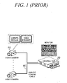
- FIG.1 shows the construction of a conventional DVR system.
- a video signal captured by each video camera 10 is converted into an analog video signal by a video encoder embedded in the video camera 10 to be applied to a DVR 20 through a cable 15.
- the analog video signal inputted to the DVR 20 is converted into digital video data through a video decoder chip, compressed by a moving picture encoder, and then stored in a hard disc.
- the video signal outputted from the video camera 10 is an analog signal and it is inputted to the DVR 20 through a coaxial cable 15.
- the cable 15 connected between the video camera 10 and DVR 20 transfers analog signals while the video camera 10 and DVR 20 handles digital signals.
- the cable 15 must be connected between the video camera 10 and DVR 20 in a one-to-one manner because it should transmit analog signals, which makes it difficult to install the cable and results in increased installation cost. For instance, in the case where 1600 video cameras are installed in a large building, 1600 cables are required.
- FIG.2 shows the construction of a conventional network camera and network DVR.
- Techniques associated with the network DVR are disclosed in International Patent Publication WO 2002/80033 and Korean Patent Laid-Open Publication No. 2002-0018988.
- a network camera 55 has a camera module 30 and a moving picture encoder 50 embedded therein in order not to use analog cables that are costly and occupy a large installation space.
- the camera module 30 and moving picture encoder 50 can be integrated into the network camera 55 or separated from the network camera.
- the camera module is directly connected to the moving picture encoder in digital fashion.
- the network camera separated from the camera module and moving picture encoder includes a video decoder chip instead of the camera module so as to receive analog video signals transmitted from a conventional video camera.
- the separation type network camera is generally installed in close proximity to the video camera to be connected with the video camera through a coaxial cable as short as several meters.
- a digital video signal inputted to the moving picture encoder 50 embedded in the network camera 55 is digitally compressed and outputted as bit stream data.
- This bit stream data is transmitted to the network DVR 60 through a network 70 such as the Ethernet.
- Moving image data transmitted from each network camera is displayed on the monitor of the network DVR 60 in real time and, simultaneously, stored in a hard disc.
- the operator of the network DVR 60 can reproduce, transmit or back up the stored data if required.
- the network cameras use the network 70, but not analog cables, in order to transmit images so that they can be easily connected in parallel with the network 70 within a range that does not exceed the bandwidth of the network 70 using parallelism that is characteristic of the Ethernet. Accordingly, the number of network LAN cables 70 for connecting the network cameras to the network DVR becomes remarkably smaller than that of the network cameras so that the space and cost for installing cables can be decreased.
- the DVR has a function of displaying a video signal inputted thereto on its monitor in real time and a function of recording the digitally compressed video data in a hard disc.
- display when the operator operates the DVR, he/she wants to display all of images captured by cameras on the monitor in real time (30 frames per second in the case of NTSC and 25 frames per second in the case of PAL, explanation is made based on NTSC hereinafter).
- the operator wants to record the images at a speed as low as 1-8fps, but not at the maximum speed, in order to save the hard disc space because real-time recording at the same speed as the displaying speed (30 frames per second) requires a hard disc capacity several times the capacity needed for low-speed recording.
- the conventional DVR shown in FIG.1 generally includes a real-time display board that displays video signals outputted from video cameras in real time all the time and a capture board for recording by which a user can record images at a desired speed within a range of less than 30 frames per second for each camera.
- the network camera and network DVR shown in FIG.2 have technical problems due to the' aforementioned requirement.
- the network camera converts a video signal captured by the camera module 30 into digital video data, compresses the converted digital video data through the moving picture compressor 50 to transmit the compressed data to the network DVR 60 through the network 70.
- the network DVR 60 stores the compressed data in a hard disc and, simultaneously, decompresses the compressed data to display it on the monitor.
- the display speed and recording speed of the network DVR become identical to each other theoretically when the network camera compresses images to transmit them to the network DVR.
- the moving picture compression technique such as MPEG is based on an algorithm that compresses a moving picture on the basis of a difference between a current frame and a previous frame of the moving picture to reduce the size of compressed bit stream data.
- bit stream data cannot be extracted at a low rate corresponding to 1 - 29 frames per second and VHS-graded resolution from bit stream data compressed at 30 frames per second and DVD-graded resolution.
- the operator has no choice but to select one of a method of recording images at a high speed corresponding to the real-time display speed or a method of displaying the images at a low speed corresponding to a low recording speed.
- bit stream data compressed at a rate of 30 frames per second bit stream data with the same picture quality as that of the compressed data and 1-29 frames per second can be extracted.
- the JPEG or Wavelet compression technique has a compression ratio lower than that of the MEPG method so as to increase storage capacity twice to three times for the same resolution.
- the present invention is directed to a network camera and a network digital video recorder that substantially obviate one or more problems due to limitations and disadvantages of the related art.
- An object of the present invention is to provide a data processing method and apparatus in a network camera and network digital video recorder system, which can simultaneously satisfy two conflicting requirements for displaying a moving image with high picture quality and smooth motion on a monitor in real time and recording the moving image at a low speed and low picture quality to save the capacity of a hard disc while using a moving picture compression technique such as MPEG.
- a network camera including a first moving picture encoder for real-time moving picture display and a second moving picture encoder for recording.
- the first and second moving picture encoders compress a digital image captured by the camera module at different picture qualities and rates (the number of frames per second) separately from each other and transmit the separately compressed images to a network DVR.
- a network digital video recorder that receives data, which is obtained by dually compressing an image at different picture qualities and rates, from the network cameras through a network, decompresses data compressed by a first moving picture encoder to display it on a monitor in real time, and stores data compressed by a second moving picture encoder without decompressing it.
- the network DVR can reproduce, transmit or backs up the stored data if required.
- the present invention applies a moving picture compression algorithm that compresses moving pictures with a very high compression ratio, such as MPEG, H.263 and differential wavelet, instead of the still image compression algorithm such as JPEG and wavelet to the network camera and network DVR.
- a moving picture compression algorithm that compresses moving pictures with a very high compression ratio, such as MPEG, H.263 and differential wavelet, instead of the still image compression algorithm such as JPEG and wavelet to the network camera and network DVR.
- FIG.3 shows the construction of the network camera and network DVR according to the present invention.
- the network camera shown in FIG.3 is a separation type network camera that does not include a camera module.
- the network camera receives analog video signals from a conventional video camera 10.
- the present invention converts an analog video signal inputted from the video camera 10 into digital video data through a video decoder 110 of the network camera and multiplexes the digital video data to apply the multiplexed data items to first and second moving picture encoders 120 and 130, respectively.
- the first and second moving picture encoders 120 and 130 compress the received data items separately from each other.
- the network camera can have two video decoders 110.
- the two video decoders can be respectively connected to the two moving picture encoders 120 and 130.
- the first moving picture encoder 120 is a moving picture compressor only for real-time moving picture display. To display an image with the highest picture quality and smooth motion within a bandwidth of a network, the first moving picture encoder 120 compresses the video data at a low compression ratio, the maximum rate and the maximum resolution.
- the first moving picture encoder can compress the video data at 30 frames per second with 740 x 480 resolution in the case of NTSC images and at 25 frames per second with 720x576 resolution in the case of PAL images.
- a bitrate that is inversely proportional to the compression ratio is generally used rather than the compression ratio.
- the highest picture quality as high as DVD grade can be achieved when images are compressed at a bitrate corresponding to 4-5Mbps through CBR (Constant Bit-Rate) control. If the network has an insufficient bandwidth, compression can be performed at a higher compression ratio (lower bitrate), lower resolution and lower rate.
- the second moving picture encoder 130 is a moving picture compressor only for recording. In general, recording is carried out at a lower speed and picture quality than those of the displaying operation in order to reduce the bandwidth and hard disc capacity.
- data is compressed at 4 frames per second through VBR (Variable Bit-Rate) using MPEG-4 algorithm. Since the second moving picture encoder independently compresses the video data, it can compress the video data at the same rate and picture quality as those of the real-time display if the operator wants to do and there are sufficient hard disc capacity and bandwidth.
- VBR Very Bit-Rate
- the moving picture encoders can set resolutions as well as picture qualities and rates separately from each other because the two video decoders can carry out analog-digital conversion at different resolutions.
- the manufacturing cost is slightly increased because the two video decoders are used.
- a central processing unit (CPU) 140 controls the video decoder 110, first and second video encoders 120 and 130.
- a software used for the central control unit 140 to execute its control operation is generally stored in a flash memory 141.
- the central processing unit 140 can control a network chip 150 for the Ethernet and a transceiver (not shown), used for transmitting the video data through a network 160 such as the Ethernet.
- the central processing unit 140 transmits bit stream packets compressed through the two moving picture compressors to a network digital video recorder 170 through the Ethernet 160 with TCP/IP or UDP/IP protocol.
- the video camera 10, video decoder 110, first and second moving picture encoders 120 and 130, central processing unit 140 and network chip 150 can be integrated into a single network camera system or constructed separately from one another.
- the hardware circuit can be simplified in such a manner that the two moving picture encoders are integrated into the central processing unit if the central processing unit integrated with the moving picture encoders has a sufficiently high processing speed and can be directly interfaced with the video decoder.
- the network DVR 170 receives the bit stream data, which is obtained by dually compressing a single image captured by the network camera. Then, the network digital video recorder 170 decompresses the data compressed by the first moving picture encoder 120 to display it on a monitor in real time (175 and 180) and stores the data compressed by the second.moving picture encoder 130 without decompressing it to record the data (176 and 181).
- the operator of the network DVR 170 can reproduce, transmit or back up the recorded data if required.
- the network DVR 170 of the present invention processes all of the above-described operations through software, distinguished from the conventional DVR shown in FIG.1, so that it does not require an additional real-time display board or capture board, resulting in a simplified system configuration.
- the present invention can dually compress an image inputted to the network camera through two moving picture encoders embedded in the network camera. Furthermore, the present invention can display the image in real time and record the image through the network DVR.
- network video cameras can be connected in parallel with a network to save installation space and cost, similarly to the conventional network camera and network DVR system.
- the present invention can simultaneously satisfy the requirements of the DVR for displaying moving pictures in real time with a high picture quality and recording the moving pictures at a low speed with a low picture quality.
Landscapes
- Engineering & Computer Science (AREA)
- Multimedia (AREA)
- Signal Processing (AREA)
- Television Signal Processing For Recording (AREA)
- Closed-Circuit Television Systems (AREA)
- Studio Devices (AREA)
Applications Claiming Priority (2)
| Application Number | Priority Date | Filing Date | Title |
|---|---|---|---|
| KR10-2003-0017420A KR100537305B1 (ko) | 2003-03-20 | 2003-03-20 | 네트워크 디지털 비디오 레코더의 동영상 압축 저장 방법 |
| KR2003017420 | 2003-03-20 |
Publications (2)
| Publication Number | Publication Date |
|---|---|
| EP1460587A2 true EP1460587A2 (fr) | 2004-09-22 |
| EP1460587A3 EP1460587A3 (fr) | 2005-08-24 |
Family
ID=32822746
Family Applications (1)
| Application Number | Title | Priority Date | Filing Date |
|---|---|---|---|
| EP04005377A Withdrawn EP1460587A3 (fr) | 2003-03-20 | 2004-03-06 | Methode de compression video double pour un reseau de cameras et pour un enregistreur video numerique (vdr) |
Country Status (4)
| Country | Link |
|---|---|
| US (1) | US20040184531A1 (fr) |
| EP (1) | EP1460587A3 (fr) |
| JP (1) | JP2004289833A (fr) |
| KR (1) | KR100537305B1 (fr) |
Cited By (2)
| Publication number | Priority date | Publication date | Assignee | Title |
|---|---|---|---|---|
| EP1624695A1 (fr) * | 2004-08-05 | 2006-02-08 | Vicon Industries Inc. | Contrôle de la distribution d'un flux vidéo à différentes fréquences d'images à divers récepteurs |
| KR100644727B1 (ko) | 2004-11-29 | 2006-11-15 | (주)아이디스 | 원격 영상 및 음향 감시 장치 및 방법 |
Families Citing this family (20)
| Publication number | Priority date | Publication date | Assignee | Title |
|---|---|---|---|---|
| US20050278642A1 (en) * | 2004-06-10 | 2005-12-15 | Chang Nelson L A | Method and system for controlling a collaborative computing environment |
| KR100490948B1 (ko) * | 2004-10-26 | 2005-05-24 | (주)유디피 | 영상 전송 방법 및 상기 방법을 이용하는 네트워크 카메라시스템 |
| JP2006270346A (ja) * | 2005-03-23 | 2006-10-05 | Megachips System Solutions Inc | 映像配信システムおよびネットワークカメラ |
| WO2007043227A1 (fr) * | 2005-10-11 | 2007-04-19 | Megachips Corporation | Caméra, vidéo-enregistreur et système de caméra |
| KR100778229B1 (ko) * | 2006-02-20 | 2007-11-22 | 박창영 | 클라이언트에서의 효율적인 네트워크 동영상 검색을 위한다중 동영상저장, 검색지원 네트워크 보안시스템 |
| KR100831704B1 (ko) * | 2006-10-13 | 2008-05-26 | 주식회사 엠아이비전 | 듀얼코덱을 이용한 영상처리보드 및 이를 이용한 고화질의영상표시 방법 |
| US20080225940A1 (en) * | 2007-03-16 | 2008-09-18 | Chen Ma | Digital video apparatus and method thereof for video playing and recording |
| US8571384B2 (en) | 2007-03-16 | 2013-10-29 | Realtek Semiconductor Corp. | Digital video recorder, digital video system, and video playback method thereof |
| US8965183B1 (en) * | 2008-01-30 | 2015-02-24 | Dominic M. Kotab | Systems and methods for creating and storing reduced quality video data |
| US9232174B1 (en) | 2008-06-25 | 2016-01-05 | Dominic M. Kotab | Methods for receiving and sending video to a handheld device |
| JP5369599B2 (ja) * | 2008-10-20 | 2013-12-18 | 富士通株式会社 | 映像符号化装置、映像符号化方法 |
| KR100919799B1 (ko) * | 2008-12-08 | 2009-10-01 | (주)리얼허브 | 폐쇄회로티브이의 고화질 영상 제공 시스템 |
| JP2011053655A (ja) * | 2009-08-07 | 2011-03-17 | Sanyo Electric Co Ltd | 画像表示制御装置およびそれを搭載した撮像装置、ならびに画像処理装置およびそれを用いた撮像装置 |
| US10028018B1 (en) * | 2011-03-07 | 2018-07-17 | Verint Americas Inc. | Digital video recorder with additional video inputs over a packet link |
| US20120294586A1 (en) * | 2010-11-18 | 2012-11-22 | David John Weaver | Controlling time-sensitive content in a time-shifted environment |
| JP2014191849A (ja) * | 2013-03-27 | 2014-10-06 | Dainippon Printing Co Ltd | 画像記憶装置、画像記憶方法、画像記憶装置用のプログラム、および、撮像装置 |
| KR101305356B1 (ko) * | 2013-04-17 | 2013-09-06 | 주식회사 씨트링 | 더블 인코딩한 영상을 표시하는 방법 및 장치 |
| US9800842B2 (en) | 2013-04-22 | 2017-10-24 | Utc Fire & Security Corporation | Efficient data transmission |
| WO2016201562A1 (fr) * | 2015-06-18 | 2016-12-22 | University Of New Brunswick | Systèmes et procédés d'imagerie de caméra |
| KR102509939B1 (ko) | 2015-10-13 | 2023-03-15 | 삼성전자 주식회사 | 전자 장치 및 전자 장치의 영상 인코딩 방법 |
Citations (6)
| Publication number | Priority date | Publication date | Assignee | Title |
|---|---|---|---|---|
| EP0979009A2 (fr) * | 1998-08-05 | 2000-02-09 | Matsushita Electronics Corporation | Système, appareil et caméra de surveillance et de télésurveillance |
| WO2000033568A1 (fr) * | 1998-11-30 | 2000-06-08 | Diva Systems Corporation | Procede et appareil de production de television en temps reel a la demande |
| US20020051061A1 (en) * | 2000-10-28 | 2002-05-02 | Alcatel | Image monitoring |
| US6414725B1 (en) * | 1998-04-16 | 2002-07-02 | Leitch Technology Corporation | Method and apparatus for synchronized multiple format data storage |
| US20020194610A1 (en) * | 2001-06-15 | 2002-12-19 | Kuo-Liang Lin | Surveillance digital video recorder |
| US20030025599A1 (en) * | 2001-05-11 | 2003-02-06 | Monroe David A. | Method and apparatus for collecting, sending, archiving and retrieving motion video and still images and notification of detected events |
Family Cites Families (7)
| Publication number | Priority date | Publication date | Assignee | Title |
|---|---|---|---|---|
| JPH07177464A (ja) * | 1993-12-16 | 1995-07-14 | Pioneer Video Corp | リアルタイム画像圧縮処理装置 |
| JP3570785B2 (ja) * | 1995-07-18 | 2004-09-29 | 株式会社ルネサステクノロジ | 動画像伸張再生方法および装置 |
| KR0176157B1 (ko) * | 1995-08-14 | 1999-05-01 | 김광호 | 개선된 검색기능을 갖는 cctv시스템 및 이에 적합한 검색방법 |
| US6466248B1 (en) * | 2000-04-05 | 2002-10-15 | Dialogic Corporation | Videoconference recording |
| US6442328B1 (en) * | 2000-05-31 | 2002-08-27 | Keen Personal Media, Inc. | Digital video recorder connectable to an auxiliary interface of a set-top box that provides video data stream to a display device based on selection between recorded video signal received from the dig |
| KR100414159B1 (ko) * | 2001-06-15 | 2004-01-07 | 주식회사 성진씨앤씨 | 다채널 입력의 고화질 다중 화면 분할 장치 및 방법 |
| US8505063B2 (en) * | 2002-02-22 | 2013-08-06 | Qwest Communications International Inc. | Systems and methods for providing redundant back-up to a video transmission system |
-
2003
- 2003-03-20 KR KR10-2003-0017420A patent/KR100537305B1/ko not_active IP Right Cessation
-
2004
- 2004-03-06 EP EP04005377A patent/EP1460587A3/fr not_active Withdrawn
- 2004-03-19 JP JP2004080499A patent/JP2004289833A/ja active Pending
- 2004-03-19 US US10/803,908 patent/US20040184531A1/en not_active Abandoned
Patent Citations (6)
| Publication number | Priority date | Publication date | Assignee | Title |
|---|---|---|---|---|
| US6414725B1 (en) * | 1998-04-16 | 2002-07-02 | Leitch Technology Corporation | Method and apparatus for synchronized multiple format data storage |
| EP0979009A2 (fr) * | 1998-08-05 | 2000-02-09 | Matsushita Electronics Corporation | Système, appareil et caméra de surveillance et de télésurveillance |
| WO2000033568A1 (fr) * | 1998-11-30 | 2000-06-08 | Diva Systems Corporation | Procede et appareil de production de television en temps reel a la demande |
| US20020051061A1 (en) * | 2000-10-28 | 2002-05-02 | Alcatel | Image monitoring |
| US20030025599A1 (en) * | 2001-05-11 | 2003-02-06 | Monroe David A. | Method and apparatus for collecting, sending, archiving and retrieving motion video and still images and notification of detected events |
| US20020194610A1 (en) * | 2001-06-15 | 2002-12-19 | Kuo-Liang Lin | Surveillance digital video recorder |
Cited By (2)
| Publication number | Priority date | Publication date | Assignee | Title |
|---|---|---|---|---|
| EP1624695A1 (fr) * | 2004-08-05 | 2006-02-08 | Vicon Industries Inc. | Contrôle de la distribution d'un flux vidéo à différentes fréquences d'images à divers récepteurs |
| KR100644727B1 (ko) | 2004-11-29 | 2006-11-15 | (주)아이디스 | 원격 영상 및 음향 감시 장치 및 방법 |
Also Published As
| Publication number | Publication date |
|---|---|
| EP1460587A3 (fr) | 2005-08-24 |
| US20040184531A1 (en) | 2004-09-23 |
| KR20040082765A (ko) | 2004-09-30 |
| JP2004289833A (ja) | 2004-10-14 |
| KR100537305B1 (ko) | 2005-12-16 |
Similar Documents
| Publication | Publication Date | Title |
|---|---|---|
| EP1460587A2 (fr) | Methode de compression video double pour un reseau de cameras et pour un enregistreur video numerique (vdr) | |
| US8265168B1 (en) | Providing trick mode for video stream transmitted over network | |
| US8160129B2 (en) | Image pickup apparatus and image distributing method | |
| US20100303436A1 (en) | Video processing system, video processing method, and video transfer method | |
| US20090290645A1 (en) | System and Method for Using Coded Data From a Video Source to Compress a Media Signal | |
| US20060013495A1 (en) | Method and apparatus for processing image data | |
| JPH09130697A (ja) | アナログとデジタルビデオモードを有する受信器及びその受信方法 | |
| JP4157887B2 (ja) | 静止画像を共に出力する保安監視システム | |
| US11395017B2 (en) | High-quality, reduced data rate streaming video production and monitoring system | |
| US20020126211A1 (en) | Digital camera | |
| US9602794B2 (en) | Video processing system and video processing method | |
| WO2005053300A2 (fr) | Systeme de controle et de production de sequences video a debit binaire reduit de qualite | |
| US7447364B2 (en) | Video image capturing and displaying method and system applying same | |
| EP1566968A1 (fr) | Système de télévision numérique en circuit fermé | |
| KR200318389Y1 (ko) | 이중 동영상 압축 방법을 적용한 네트워크 카메라와네트워크 디지털 비디오 레코더 | |
| KR101429505B1 (ko) | 영상 재생장치 | |
| JPH10117302A (ja) | ビデオカメラ及び通信システム | |
| KR100778118B1 (ko) | 네트워크로의 영상신호 전송기능을 향상한 dvr장치 및그의 영상신호 압축방법 | |
| EP0843483B1 (fr) | Méthode de décodage de données vidéo codées | |
| JP5131954B2 (ja) | ビデオレコーダ並びにカメラシステム | |
| KR200370249Y1 (ko) | 하드웨어 mpeg4 코덱 및 v2oip 프로토콜을이용한 실시간 팬/틸트/줌 제어가 가능한 네트워크카메라 시스템 | |
| KR100479802B1 (ko) | 분산처리형 디지털 비디오 레코더 | |
| JP5249265B2 (ja) | テレビインターホン装置 | |
| JP2006270346A (ja) | 映像配信システムおよびネットワークカメラ | |
| JP4787811B2 (ja) | 映像信号多重伝送装置及び映像信号多重伝送装置を用いた撮像装置 |
Legal Events
| Date | Code | Title | Description |
|---|---|---|---|
| PUAI | Public reference made under article 153(3) epc to a published international application that has entered the european phase |
Free format text: ORIGINAL CODE: 0009012 |
|
| AK | Designated contracting states |
Kind code of ref document: A2 Designated state(s): AT BE BG CH CY CZ DE DK EE ES FI FR GB GR HU IE IT LI LU MC NL PL PT RO SE SI SK TR |
|
| AX | Request for extension of the european patent |
Extension state: AL LT LV MK |
|
| PUAL | Search report despatched |
Free format text: ORIGINAL CODE: 0009013 |
|
| AK | Designated contracting states |
Kind code of ref document: A3 Designated state(s): AT BE BG CH CY CZ DE DK EE ES FI FR GB GR HU IE IT LI LU MC NL PL PT RO SE SI SK TR |
|
| AX | Request for extension of the european patent |
Extension state: AL LT LV MK |
|
| RIC1 | Information provided on ipc code assigned before grant |
Ipc: 7H 04N 5/76 B Ipc: 7H 04N 7/18 A |
|
| AKX | Designation fees paid | ||
| STAA | Information on the status of an ep patent application or granted ep patent |
Free format text: STATUS: THE APPLICATION IS DEEMED TO BE WITHDRAWN |
|
| 18D | Application deemed to be withdrawn |
Effective date: 20060225 |
|
| REG | Reference to a national code |
Ref country code: DE Ref legal event code: 8566 |
|
| RIN1 | Information on inventor provided before grant (corrected) |
Inventor name: LIM, IN-KEON Inventor name: LIM, BYEONG-JIN |