EP1460464B1 - Optischer Steckverbinder mit einem beschichteten Faserstück als Koppelglied - Google Patents
Optischer Steckverbinder mit einem beschichteten Faserstück als Koppelglied Download PDFInfo
- Publication number
- EP1460464B1 EP1460464B1 EP04006405A EP04006405A EP1460464B1 EP 1460464 B1 EP1460464 B1 EP 1460464B1 EP 04006405 A EP04006405 A EP 04006405A EP 04006405 A EP04006405 A EP 04006405A EP 1460464 B1 EP1460464 B1 EP 1460464B1
- Authority
- EP
- European Patent Office
- Prior art keywords
- optical
- optical fiber
- fiber
- longitudinal ends
- clamp
- Prior art date
- Legal status (The legal status is an assumption and is not a legal conclusion. Google has not performed a legal analysis and makes no representation as to the accuracy of the status listed.)
- Expired - Lifetime
Links
Images




Classifications
-
- G—PHYSICS
- G02—OPTICS
- G02B—OPTICAL ELEMENTS, SYSTEMS OR APPARATUS
- G02B6/00—Light guides; Structural details of arrangements comprising light guides and other optical elements, e.g. couplings
- G02B6/24—Coupling light guides
- G02B6/36—Mechanical coupling means
- G02B6/38—Mechanical coupling means having fibre to fibre mating means
- G02B6/3807—Dismountable connectors, i.e. comprising plugs
- G02B6/3833—Details of mounting fibres in ferrules; Assembly methods; Manufacture
- G02B6/3846—Details of mounting fibres in ferrules; Assembly methods; Manufacture with fibre stubs
-
- E—FIXED CONSTRUCTIONS
- E03—WATER SUPPLY; SEWERAGE
- E03B—INSTALLATIONS OR METHODS FOR OBTAINING, COLLECTING, OR DISTRIBUTING WATER
- E03B3/00—Methods or installations for obtaining or collecting drinking water or tap water
- E03B3/06—Methods or installations for obtaining or collecting drinking water or tap water from underground
- E03B3/08—Obtaining and confining water by means of wells
- E03B3/15—Keeping wells in good condition, e.g. by cleaning, repairing, regenerating; Maintaining or enlarging the capacity of wells or water-bearing layers
-
- E—FIXED CONSTRUCTIONS
- E03—WATER SUPPLY; SEWERAGE
- E03B—INSTALLATIONS OR METHODS FOR OBTAINING, COLLECTING, OR DISTRIBUTING WATER
- E03B3/00—Methods or installations for obtaining or collecting drinking water or tap water
- E03B3/06—Methods or installations for obtaining or collecting drinking water or tap water from underground
- E03B3/08—Obtaining and confining water by means of wells
- E03B3/12—Obtaining and confining water by means of wells by means of vertical pipe wells
-
- G—PHYSICS
- G02—OPTICS
- G02B—OPTICAL ELEMENTS, SYSTEMS OR APPARATUS
- G02B6/00—Light guides; Structural details of arrangements comprising light guides and other optical elements, e.g. couplings
- G02B6/24—Coupling light guides
- G02B6/36—Mechanical coupling means
- G02B6/38—Mechanical coupling means having fibre to fibre mating means
- G02B6/3807—Dismountable connectors, i.e. comprising plugs
- G02B6/381—Dismountable connectors, i.e. comprising plugs of the ferrule type, e.g. fibre ends embedded in ferrules, connecting a pair of fibres
- G02B6/3825—Dismountable connectors, i.e. comprising plugs of the ferrule type, e.g. fibre ends embedded in ferrules, connecting a pair of fibres with an intermediate part, e.g. adapter, receptacle, linking two plugs
-
- G—PHYSICS
- G02—OPTICS
- G02B—OPTICAL ELEMENTS, SYSTEMS OR APPARATUS
- G02B6/00—Light guides; Structural details of arrangements comprising light guides and other optical elements, e.g. couplings
- G02B6/24—Coupling light guides
- G02B6/255—Splicing of light guides, e.g. by fusion or bonding
- G02B6/2558—Reinforcement of splice joint
Definitions
- This invention relates to an optical connector for conneding optical fibers by bringing longitudinal end faces of the optical fibers into contact with each other.
- optical connector of the type is disclosed, for example, in United States Patent No. 6,491,442 as an optical fiber connector.
- the optical fiber connector By the use of the optical fiber connector, it is possible to suitably connect an optical system.
- an outer member holds a portion of an optical fiber remote from its connecting end which is connectable to a connecting end of a counterpart optical fiber.
- An aligning member is held by the outer member so as to be movable along the optical fiber.
- the aligning member carries out positioning of the connecting end of the optical fiber.
- the aligning member is urged by a spring in a direction to project from the outer member.
- the aligning member When connecting the optical fiber to the counterpart optical fiber, the aligning member is moved in a direction opposite to the foregoing direction against an urging force applied by the spring. So that, the connecting end of the optical fiber is projected from the aligning member and is brought in press contact with the connecting end of the counterpart optical fiber with bending of at least one of the optical fibers.
- the US 5,963,692 discloses a plug for an optical fiber plug connector.
- a pre-fitted optical fiber section is held in a plug ferrule in such a way that it extends from a front face up to a lateral fusion access aperture in the plug ferrule. From the direction of an entry surface at the cable-end, a bore running coaxially to the optical fiber section also leads into the fusion access aperture. Within the fusion access aperture, the pre-fitted optical fiber section can be welded to the optical fiber of an optical fiber cable in the field.
- connection apparatus capable of connecting an optical system with high accuracy and at low cost.
- optical connector and the optical connector element according to the invention are defined by independent claims I and II respectively.
- the optical connector illustrated in the figure is for use in connecting an optical system and comprises an optical connector plug 12 as a first connector element holding a first optical fiber group 11 and an optical connector plug 14 as a second connector element holding a second optical fiber group 13.
- Each of the first and the second optical fiber groups 11 and 13 includes a number of optical fibers.
- Each of the optical fibers of the first optical fiber group 11 will be called a first optical fiber.
- Each of the optical fibers of the second optical fiber group 13 will be called a second optical fiber.
- the optical connector plugs 12 and 14 are connected to each other by an optical connector adapter 21.
- the optical connector adapter 21 has a number of V grooves 21a.
- Each optical fiber of the first optical fiber group 11, i.e., the first optical fiber and each optical fiber of the second optical fiber group 13, i.e., the second optical fiber are positioned to face to each other in each V groove 21a.
- each optical fiber of the first optical fiber group 11 and each optical fiber of the second optical fiber group 13 are brought into contact with each other.
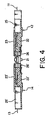
- bending of each optical fiber of the first optical fiber group 11 occurs as clearly shown in Fig. 4.
- each optical fiber of the first optical fiber group 11 is brought into strong contact with each optical fiber of the second optical fiber group 11 so as to connect the optical system with high precision.
- each optical fiber of the second optical fiber group 13 is prevented from occurrence of bending by a structure which will later be described.
- the optical connector plug 12 comprises a frame-like main body 22 made of plastic and having a generally rectangular shape, a plastic cover 22 covering the main body 22, four holding portions or clamp portions 25 made of plastic and clamping or holding the first optical fiber group 11, and a fiber protector 26 made of metal and attached to an end of the main body 22 to protect an end of each optical fiber of the first optical fiber group 11.
- the clamp portions 25 are arranged in parallel and adjacent to each other and inserted into a receiving portion 22a of the body 22.
- the cover 23 serves to protect the first optical fiber group 11.
- the optical connector plug 14 is similar in structure to the optical connector plug 12. Corresponding parts are designated by like reference numerals with an apostrophe.
- An elastic member 19 is attached to a lower surface of a cover 23'.
- the elastic member 19 serves to press the second optical fiber group 13 to prevent occurrence of the above-mentioned bending.
- the elastic member 19 may be formed integral with the cover 23'. Alternatively, the elastic member 19 may be a separate component made of rubber or the like and attached to the cover 23'.
- a pair of the optical connector plugs to be connected to each other may have a first structure in which the optical fiber is bent and a second structure in which the optical fiber is not bent In case of the second structure, the optical fiber is pressed by the elastic member attached to the lower surface of the cover.
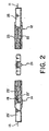
- the optical fiber 31 has a long fiber portion 33 positioned on the right side of a line 32 and a short fiber portion 34 positioned on the left side of the line 32.
- the long fiber portion 33 and the short fiber portion 34 are connected at a fusion connection portion 35 by fusion connection.
- the long fiber portion 33 is an ordinary optical fiber and comprises a tape-covered part 33a covered with a tape and a tape-removed part 33b where the tape is removed.
- the length L2 of the tape-removed part 33b is equal to 6 mm.
- the short fiber portion 34 comprises a special optical fiber having a polymer layer on its outer peripheral surface and is designed to have high breakage resistance as compared with the ordinary optical fiber.
- the short fiber portion 34 comprises a polymer-coated part 34a coated with the polymer layer and a polymer-removed part 34b where the polymer layer is removed.
- the length L1 of the polymer-removed part L1 is equal to 3 mm.
- the clamp portion 25 has an opening portion 25a formed on its upper side, an adhesive filling part 25b continued from the opening portion 25a, and a narrow hole 25c through which the short fiber portion 34 is inserted.
- an adhesive for convenlence of illustration, only a part of the adhesive is depicted by a reference numeral 37
- the adhesive is filled within a range depicted by L3.
- the optical connector plug 14 has a similar structure.
- the special optical fiber of the optical connector plug 12 and the special optical fiber of the optical connector plug 14 are positioned with respect to each other and contacted with each other.
- the ordinary optical fiber is degraded in strength at a portion where coating is removed.
- the tape-removed part 33a, the fusion connection portion 35, and the polymer-removed part 34b are protected by the adhesive within the clamp portion 25, the optical fiber 31 as a whole is not deteriorated in mechanical characteristics and is hardly affected by the change in environment, such as temperature and humidity.
- Fig. 8A shows connection loss due to fusion bonding between the special optical fiber having the polymer layer and the ordinary optical fiber.
- Fig. 8B shows connection loss due to fusion bonding between the ordinary optical fibers.
- N represents the connection loss (dB).
- connection loss is within a practically allowable range.
- the polymer layer at an end of the short fiber portion 34 is peeled off due to discharge during fusion bonding and, therefore, the outer diameter of the polymer-removed part 34b is reduced (for example, 0.115 mm).
- the connection loss due to fusion bonding the value in case of connection between the special optical fiber and the ordinary optical fiber is comparable to that in case of connection between the ordinary optical fibers.
- the average value of the connection loss N is equal to 0.028 and the standard deviation is equal to 0.015.
- the average value of the connection loss N is equal to 0.025 and the standard deviation is equal to 0.017.
- the optical connector plug 12 After the short fiber portion 34 and the long fiber portion 33 are fusion bonded and connected to each other, the optical fiber 31 is fixed to each clamp portion 25. After a predetermined number of the optical fibers 31 are fixed, the clamp portions 25 are fixed to the receiving portion 22a of the main body 22. Each clamp portion 25 is a separate component Independent of the main body 22, assembling is easy.
- the optical connector plug 14 is assembled in the similar manner.
Landscapes
- Physics & Mathematics (AREA)
- General Physics & Mathematics (AREA)
- Optics & Photonics (AREA)
- Engineering & Computer Science (AREA)
- Environmental & Geological Engineering (AREA)
- Health & Medical Sciences (AREA)
- Life Sciences & Earth Sciences (AREA)
- Hydrology & Water Resources (AREA)
- Public Health (AREA)
- Water Supply & Treatment (AREA)
- Mechanical Coupling Of Light Guides (AREA)
Claims (11)
- Optischer Verbinder mit
einem ersten Verbindungselement (12), das eine erste optische Faser (11) hält, und einem zweiten Verbindungselement (14) das eine zweite optische Faser (13) hält, wobei das erste und das zweite Verbindungselement (12,14) miteinander zusammenwirken, um einen Verbindungszustand zu erzielen, bei dem freiliegende Längsenden der ersten und der zweiten optischen Faser (11, 13) in Kontakt miteinander gebracht werden,
wobei die erste optische Faser enthält:einen langen Faserabschnitt (33) mit Längsenden,einen kurzen Faserabschnitt (34), der eine höhere Bruchfestigkeit aufweist als der lange Faserabschnitt (33) und der Längsenden hat, undeinen Schmelzverbindungsabschnitt (35), an dem eines der Längsenden des kurzen Faserabschnitts (34) mit einem der Längsenden des langen Faserabschnitts (33) schmelzverbunden ist, wobei ein anderes der Längsenden des kurzen Faserabschnitts (34) freiliegt, um als freiliegendes Längsende der ersten optischen Faser (11) zu dienen;gekennzeichnet dadurch, dass das erste Verbindungselement (12) enthält:einen Hauptkörper (22),einen Klemmabschnitt (25), der die erste optische Faser (11) hält, undeine Abdeckung (23), die den Klemmabschnitt (25) an dem Hauptkörper (22) befestigt, unddadurch, dass der Schmelzverbindungsabschnitt (35) zwischen dem langen Faserabschnitt (33) und dem kurzen Faserabschnitt (34) innerhalb des Klemmabschnitts (25) gehalten ist, unddadurch, dass der kurze Faserabschnitt (34), der eine höhere Bruchfestigkeit aufweist als der lange Faserabschnitt (33), in einem Verbindungszustand des optischen Verbinders gebogen ist. - Optischer Verbinder nach Anspruch 1, bei dem
der Klemmabschnitt (25) einen Öffnungsabschnitt (25a) aufweist und
der Schmelzverbindungsabschnitt (35) in dem Öffnungsabschnitt (25a) angeordnet ist. - Optischer Verbinder nach Anspruch 2, bei dem
der Öffnungsabschnitt (25a) mit einem Kleber gefüllt ist und
der Schmelzverbindungsabschnitt (35) von dem Kleber geschützt wird. - Optischer Verbinder nach Anspruch 1, bei dem die zweite optische Faser (13) enthält:einen langen Faserabschnitt (33) mit Längsenden,einen kurzen Faserabschnitt (34), der eine höhere Bruchfestigkeit aufweist als der lange Faserabschnitt (33) zweiten optischen Faser (13) und der Längsenden hat, undeinen Schmelzverbindungsabschnitt (35), an dem eines der Längsenden des kurzen Faserabschnitts (34) der zweiten optischen Faser (13) mit einem der Längsenden des langen Faserabschnitts (33) der zweiten optischen Faser (13) schmelzverbunden ist, wobei ein anderes der Längsenden des kurzen Faserabschnitts (34) der zweiten optischen Faser (13) freiliegt, um als freiliegendes Längsende der zweiten optischen Faser (13) zu dienen.
- Optischer Verbinder nach Anspruch 4, bei dem der Verbindungszustand begleitet ist durch das Biegen zumindest eines der kurzen Faserabschnitte (34) der ersten bzw. der zweiten optischen Faser (11, 13).
- Optischer Verbinder nach Anspruch 4, bei dem das zweite Verbindungselement (14) enthält:einen Hauptkörper (22'),einen Klemmabschnitt (25'), der die zweite optische Faser (13) hält, undeine Abdeckung (23'), die den Klemmabschnitt (25') an dem Hauptkörper (22') befestigt, und
- Optischer Verbinder nach Anspruch 6, bei dem
der Klemmabschnitt (25') des zweiten Verbindungselements (14) einen Öffnungsabschnitt aufweist und
der Schmelzverbindungsabschnitt (35) der zweiten optischen Faser (13) in dem Öffnungsabschnitt des Klemmabschnitts (25') des zweiten Verbindungselements (14) angeordnet ist. - Optischer Verbinder nach Anspruch 7, bei dem
der Öffnungsabschnitt des Klemmabschnitts (25') des zweiten Verbindungselements (14) mit einem Kleber gefüllt ist und
der Schmelzverbindungsabschnitt (35) der zweiten optischen Faser (13) von dem Kleber in dem Öffnungsabschnitt des Klemmabschnitts (25') des zweiten Verbindungselements (14) geschützt wird. - Optischer Verbinder nach Anspruch 1 mit
einem Adapter (21) zum Aufnehmen der Längsenden der ersten und der zweiten optischen Faser (11, 13), wenn der Verbindungszustand erreicht ist. - Optischer Verbinder nach Anspruch 1, bei dem der kurze Faserabschnitt (34) eine auf seiner Außenfläche ausgebildete Polymerschicht aufweist.
- Verbindungselement zum Ausbilden eines Verbindungsobjekts mit
einer optischen Faser (11),
einem Hauptkörper (22),
einem Klemmabschnitt (25), der die optische Faser (11) hält, und
einer Abdeckung (23), die den Klemmabschnitt (25) an dem Hauptkörper (22) befestigt;
wobei die optische Faser enthält:einen langen Faserabschnitt (33) mit Längsenden undeinen kurzen Faserabschnitt (34), der mit einem der Längsenden des langen Faserabschnitts (33) verbunden ist und eine hohe Bruchfestigkeit und Biegsamkeit aufweist, wobei der kurze Faserabschnitt (34) ein Verbindungsende aufweist, das von dem Klemmabschnitt (25) aus vorsteht, um in Kontakt mit dem Verbindungsobjekt gebracht zu werden;
dadurch gekennzeichnet, dass ein Schmelzverbindungsabschnitt (35) zwischen dem langen Faserabschnitt (33) und dem kurzen Faserabschnitt (34) innerhalb des Klemmabschnitts (25) gehalten ist, und
dadurch gekennzeichnet, dass der kurze Faserabschnitt (34), der eine höhere Bruchfestigkeit aufweist als der lange Faserabschnitt (33), in einem Verbindungszustand des optischen Verbinders gebogen ist.
Applications Claiming Priority (2)
| Application Number | Priority Date | Filing Date | Title |
|---|---|---|---|
| JP2003075168 | 2003-03-19 | ||
| JP2003075168A JP3795469B2 (ja) | 2003-03-19 | 2003-03-19 | 光コネクタ |
Publications (2)
| Publication Number | Publication Date |
|---|---|
| EP1460464A1 EP1460464A1 (de) | 2004-09-22 |
| EP1460464B1 true EP1460464B1 (de) | 2006-03-08 |
Family
ID=32821343
Family Applications (1)
| Application Number | Title | Priority Date | Filing Date |
|---|---|---|---|
| EP04006405A Expired - Lifetime EP1460464B1 (de) | 2003-03-19 | 2004-03-17 | Optischer Steckverbinder mit einem beschichteten Faserstück als Koppelglied |
Country Status (7)
| Country | Link |
|---|---|
| US (1) | US7207726B2 (de) |
| EP (1) | EP1460464B1 (de) |
| JP (1) | JP3795469B2 (de) |
| KR (1) | KR100649843B1 (de) |
| CN (1) | CN1279376C (de) |
| DE (1) | DE602004000444T2 (de) |
| TW (1) | TWI254154B (de) |
Families Citing this family (3)
| Publication number | Priority date | Publication date | Assignee | Title |
|---|---|---|---|---|
| US9575272B2 (en) * | 2012-09-07 | 2017-02-21 | Commscope Technologies Llc | Manufacturing and using ferrule-less multi-fiber connectors |
| TWI563301B (en) * | 2012-12-28 | 2016-12-21 | Hon Hai Prec Ind Co Ltd | Optical signal transmission device |
| AU2017280028B2 (en) * | 2016-06-20 | 2021-08-19 | Commscope Technologies Llc | Ferrule-less fiber optic connector |
Family Cites Families (16)
| Publication number | Priority date | Publication date | Assignee | Title |
|---|---|---|---|---|
| DE964279C (de) | 1955-07-15 | 1957-05-23 | Autol Werke G M B H | Zusatzmittel fuer Motortreibstoffe |
| GB2117916B (en) * | 1982-02-17 | 1986-08-28 | Standard Telephones Cables Ltd | Optic fibre fusion splicing |
| US5151964A (en) * | 1991-09-06 | 1992-09-29 | Minnesota Mining And Manufacturing Company | Wedge-actuated multiple optical fiber splice |
| JPH05119235A (ja) | 1991-10-25 | 1993-05-18 | Fujitsu Ltd | 光コネクター |
| US5367594A (en) * | 1992-09-01 | 1994-11-22 | The Whitaker Corporation | Fiber optic splicer-connector |
| JP2985044B2 (ja) * | 1994-10-20 | 1999-11-29 | 日本航空電子工業株式会社 | 光多芯コネクタ |
| US5694506A (en) | 1995-03-09 | 1997-12-02 | Nippon Telegraph And Telephone Corporation | Optical connector |
| JP3515677B2 (ja) * | 1996-10-09 | 2004-04-05 | 住友電気工業株式会社 | 光コネクタおよびその取付方法 |
| JPH10123366A (ja) | 1996-10-25 | 1998-05-15 | Nippon Telegr & Teleph Corp <Ntt> | 光コネクタ |
| CA2226052A1 (en) | 1997-02-13 | 1998-08-13 | Diamond Sa | Plug for an optical fiber plug connector and method of its manufacture |
| US5883995A (en) * | 1997-05-20 | 1999-03-16 | Adc Telecommunications, Inc. | Fiber connector and adapter |
| DE19826275A1 (de) * | 1998-06-12 | 1999-12-16 | Delphi Automotive Systems Gmbh | Optische Verbindungseinheit |
| KR100409112B1 (ko) | 1998-06-29 | 2003-12-11 | 니폰 덴신 덴와 가부시끼가이샤 | 광섬유 접속기 플러그, 광섬유 접속기 플러그 어셈블리, 및 광섬유 접속기 플러그 어셈블리 접속 구조 |
| JP3451217B2 (ja) | 1999-04-19 | 2003-09-29 | 日本電信電話株式会社 | 光コネクタおよびこれに用いる光アダプタ |
| JP2002082257A (ja) | 2000-09-06 | 2002-03-22 | Sumitomo Electric Ind Ltd | 光コネクタおよび光コネクタ部品 |
| US6676299B1 (en) * | 2002-11-08 | 2004-01-13 | Stratos Lightwave, Inc. | Device having multiple optical fibers |
-
2003
- 2003-03-19 JP JP2003075168A patent/JP3795469B2/ja not_active Expired - Fee Related
-
2004
- 2004-03-16 US US10/801,009 patent/US7207726B2/en not_active Expired - Fee Related
- 2004-03-17 EP EP04006405A patent/EP1460464B1/de not_active Expired - Lifetime
- 2004-03-17 DE DE602004000444T patent/DE602004000444T2/de not_active Expired - Lifetime
- 2004-03-18 TW TW093107201A patent/TWI254154B/zh not_active IP Right Cessation
- 2004-03-18 KR KR1020040018301A patent/KR100649843B1/ko not_active Expired - Fee Related
- 2004-03-18 CN CNB200410028785XA patent/CN1279376C/zh not_active Expired - Fee Related
Also Published As
| Publication number | Publication date |
|---|---|
| US20040184740A1 (en) | 2004-09-23 |
| KR20040082961A (ko) | 2004-09-30 |
| KR100649843B1 (ko) | 2006-11-24 |
| US7207726B2 (en) | 2007-04-24 |
| CN1279376C (zh) | 2006-10-11 |
| CN1550804A (zh) | 2004-12-01 |
| DE602004000444T2 (de) | 2006-08-24 |
| EP1460464A1 (de) | 2004-09-22 |
| JP2004280025A (ja) | 2004-10-07 |
| TWI254154B (en) | 2006-05-01 |
| JP3795469B2 (ja) | 2006-07-12 |
| TW200424582A (en) | 2004-11-16 |
| DE602004000444D1 (de) | 2006-05-04 |
Similar Documents
| Publication | Publication Date | Title |
|---|---|---|
| US8317406B2 (en) | Optical connector | |
| US4553814A (en) | Detachable fiber optic connector assembly | |
| JP3515677B2 (ja) | 光コネクタおよびその取付方法 | |
| US4687288A (en) | Fiber optic connector with temperature compensating mechanism | |
| US6261006B1 (en) | Environmental sealing for fiber optic cable assemblies | |
| JP5167413B2 (ja) | 光コネクタ及びその組立方法 | |
| US20060263011A1 (en) | Hybrid optical/electrical connector and adapter | |
| US4383732A (en) | Fiber optic connector | |
| US6604867B2 (en) | Fiber optic connector | |
| JP3226755B2 (ja) | 光ファイバコネクタの組立方法および接着剤注入治具 | |
| JP3451217B2 (ja) | 光コネクタおよびこれに用いる光アダプタ | |
| JP5160706B2 (ja) | 光ファイバーケーブルの端末装置 | |
| US10605994B2 (en) | Optical connector | |
| US7207726B2 (en) | Optical connector using an optical fiber having a special fiber portion as a part thereof | |
| CN101681001A (zh) | 光纤连接器及其组装方法 | |
| US6505975B2 (en) | Connector for optical fiber cord | |
| EP1233293A1 (de) | Optischer Steckverbinder | |
| WO2005010570A2 (en) | Packaging for a fiber-coupled optical device | |
| JP2001133660A (ja) | 光コネクタフェルール、光コネクタ及び光コネクタの組立て方法 | |
| JPH11248974A (ja) | 光モジュール | |
| JP2913549B1 (ja) | 多心光コネクタ | |
| JP3220855B2 (ja) | 光多芯コネクタ | |
| JP3485465B2 (ja) | 光コネクタ | |
| KR20010001994A (ko) | 다심 일괄형 광커넥터 | |
| JP2002228877A (ja) | 光コネクタ |
Legal Events
| Date | Code | Title | Description |
|---|---|---|---|
| PUAI | Public reference made under article 153(3) epc to a published international application that has entered the european phase |
Free format text: ORIGINAL CODE: 0009012 |
|
| AK | Designated contracting states |
Kind code of ref document: A1 Designated state(s): AT BE BG CH CY CZ DE DK EE ES FI FR GB GR HU IE IT LI LU MC NL PL PT RO SE SI SK TR |
|
| AX | Request for extension of the european patent |
Extension state: AL LT LV MK |
|
| 17P | Request for examination filed |
Effective date: 20041217 |
|
| 17Q | First examination report despatched |
Effective date: 20050117 |
|
| AKX | Designation fees paid |
Designated state(s): DE FR GB |
|
| GRAP | Despatch of communication of intention to grant a patent |
Free format text: ORIGINAL CODE: EPIDOSNIGR1 |
|
| GRAS | Grant fee paid |
Free format text: ORIGINAL CODE: EPIDOSNIGR3 |
|
| GRAA | (expected) grant |
Free format text: ORIGINAL CODE: 0009210 |
|
| AK | Designated contracting states |
Kind code of ref document: B1 Designated state(s): DE FR GB |
|
| REG | Reference to a national code |
Ref country code: GB Ref legal event code: FG4D |
|
| REF | Corresponds to: |
Ref document number: 602004000444 Country of ref document: DE Date of ref document: 20060504 Kind code of ref document: P |
|
| ET | Fr: translation filed | ||
| PLBE | No opposition filed within time limit |
Free format text: ORIGINAL CODE: 0009261 |
|
| STAA | Information on the status of an ep patent application or granted ep patent |
Free format text: STATUS: NO OPPOSITION FILED WITHIN TIME LIMIT |
|
| 26N | No opposition filed |
Effective date: 20061211 |
|
| PGFP | Annual fee paid to national office [announced via postgrant information from national office to epo] |
Ref country code: FR Payment date: 20120319 Year of fee payment: 9 |
|
| PGFP | Annual fee paid to national office [announced via postgrant information from national office to epo] |
Ref country code: GB Payment date: 20120314 Year of fee payment: 9 |
|
| PGFP | Annual fee paid to national office [announced via postgrant information from national office to epo] |
Ref country code: DE Payment date: 20120411 Year of fee payment: 9 |
|
| GBPC | Gb: european patent ceased through non-payment of renewal fee |
Effective date: 20130317 |
|
| REG | Reference to a national code |
Ref country code: FR Ref legal event code: ST Effective date: 20131129 |
|
| REG | Reference to a national code |
Ref country code: DE Ref legal event code: R119 Ref document number: 602004000444 Country of ref document: DE Effective date: 20131001 |
|
| PG25 | Lapsed in a contracting state [announced via postgrant information from national office to epo] |
Ref country code: DE Free format text: LAPSE BECAUSE OF NON-PAYMENT OF DUE FEES Effective date: 20131001 Ref country code: FR Free format text: LAPSE BECAUSE OF NON-PAYMENT OF DUE FEES Effective date: 20130402 Ref country code: GB Free format text: LAPSE BECAUSE OF NON-PAYMENT OF DUE FEES Effective date: 20130317 |