EP1458222A1 - Warneinrichtung für Lampenfehler - Google Patents
Warneinrichtung für Lampenfehler Download PDFInfo
- Publication number
- EP1458222A1 EP1458222A1 EP04251306A EP04251306A EP1458222A1 EP 1458222 A1 EP1458222 A1 EP 1458222A1 EP 04251306 A EP04251306 A EP 04251306A EP 04251306 A EP04251306 A EP 04251306A EP 1458222 A1 EP1458222 A1 EP 1458222A1
- Authority
- EP
- European Patent Office
- Prior art keywords
- led
- resistor
- resistors
- failure warning
- warning device
- Prior art date
- Legal status (The legal status is an assumption and is not a legal conclusion. Google has not performed a legal analysis and makes no representation as to the accuracy of the status listed.)
- Withdrawn
Links
Images
Classifications
-
- B—PERFORMING OPERATIONS; TRANSPORTING
- B60—VEHICLES IN GENERAL
- B60Q—ARRANGEMENT OF SIGNALLING OR LIGHTING DEVICES, THE MOUNTING OR SUPPORTING THEREOF OR CIRCUITS THEREFOR, FOR VEHICLES IN GENERAL
- B60Q11/00—Arrangement of monitoring devices for devices provided for in groups B60Q1/00 - B60Q9/00
- B60Q11/005—Arrangement of monitoring devices for devices provided for in groups B60Q1/00 - B60Q9/00 for lighting devices, e.g. indicating if lamps are burning or not
-
- H—ELECTRICITY
- H05—ELECTRIC TECHNIQUES NOT OTHERWISE PROVIDED FOR
- H05B—ELECTRIC HEATING; ELECTRIC LIGHT SOURCES NOT OTHERWISE PROVIDED FOR; CIRCUIT ARRANGEMENTS FOR ELECTRIC LIGHT SOURCES, IN GENERAL
- H05B45/00—Circuit arrangements for operating light-emitting diodes [LED]
- H05B45/50—Circuit arrangements for operating light-emitting diodes [LED] responsive to malfunctions or undesirable behaviour of LEDs; responsive to LED life; Protective circuits
- H05B45/58—Circuit arrangements for operating light-emitting diodes [LED] responsive to malfunctions or undesirable behaviour of LEDs; responsive to LED life; Protective circuits involving end of life detection of LEDs
-
- H—ELECTRICITY
- H05—ELECTRIC TECHNIQUES NOT OTHERWISE PROVIDED FOR
- H05B—ELECTRIC HEATING; ELECTRIC LIGHT SOURCES NOT OTHERWISE PROVIDED FOR; CIRCUIT ARRANGEMENTS FOR ELECTRIC LIGHT SOURCES, IN GENERAL
- H05B47/00—Circuit arrangements for operating light sources in general, i.e. where the type of light source is not relevant
- H05B47/20—Responsive to malfunctions or to light source life; for protection
- H05B47/24—Circuit arrangements for protecting against overvoltage
Definitions
- This invention relates to a lamp failure warning device and more particularly to a failure warning device for a light emitting diode (hereinafter called an LED).
- ECE Regulation 48 It is a requirement of ECE Regulation 48 to have a tell tale signal to the driver of a vehicle that will warn of an inoperative turn signal lamp.
- Some conventional flasher units incorporate this feature by increasing the flash rate when one of the turn signal lamps fails.
- a separate output may be provided to energise a visible or audible signal. In either case, the flasher unit determines whether a lamp has failed by monitoring the current being drawn by all the turn signal lamps. If this falls below a predetermined threshold then the failure signal is activated.
- US-B-6490512 discloses a device of this type in which a diagnostic circuit associated with a group of such LED's is arranged to apply, to the supply conductor of the LED's, a pulse width modulated signal indicating the nature of a malfunction.
- a switching and evaluation logic unit is arranged to decode and display this information.
- the present invention aims to provide a simpler device that can be used in conjunction with a conventional flasher unit.
- a failure warning device for an LED comprises current sensing means for determining whether the current flowing through the LED exceeds a threshold value and switch means for connecting a load resistor in parallel with the LED when said threshold current is exceeded.
- the current sensing means comprises a first resistor connected in series with the LED, a second resistor connected in parallel with the LED, and control means responsive the voltage across the second resistor.
- the LED and the load resistor together draw a comparable current to that drawn by the filament lamp that they have replaced. If the LED fails, the current in the first resistor is reduced, resulting in a decrease in the current therethrough and a consequent increase in the voltage across the second resistor.
- the detector means responds to this increase in voltage to open the switch so that the remaining current drawn by the device is insufficient to prevent the activation of the lamp failure warning.
- the second resistor comprises third and fourth resistors connected in series with one another.
- the resistance value of the first resistor is sufficiently low, compared with that of the third and fourth resistors, to have negligible effect on the voltage at the connection between the third and fourth resistors when no current is passing through the light emitting diode.
- the detector means may comprise a further series chain formed by fifth and sixth resistors connected in parallel with the first, third and fourth resistors and a comparator arranged to sense the voltage difference between the junction between the third and fourth resistors and the junction between the fifth and sixth resistors, the output of the comparator being connected to control the switch.
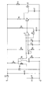
- an LED D1 is connected in series with a fuse F, a first resistor R1 and a diode D2 (which provides reverse polarity protection) to the positive output from a flasher unit.
- a zener diode TVS is connected in parallel with the LED D1, the fuse F and the first resistor R1 to provide transient overvoltage protection.
- a series chain of two resistors R3 and R4 is connected in parallel with the LED D1 and the fuse F. The junction of the resistors R3 and R4 is connected to the non-inverting input of a comparator IC, the inverting input of which is connected to the junction between two further resistors R5 and R6 that are connected in series with one another to the power supply from the diode D2.
- the values of the resistors R3, R4, R5 and R6 are chosen such that the voltage at the non-inverting input of the comparator IC is higher than the voltage at the inverting input when no current is flowing through the LED D1.
- the value of the first resistor R1 is chosen such that the additional voltage drop created when the LED D1 is drawing at least 20% of its nominal current is sufficient to lower the voltage at the non-inverting input of the comparator IC to below the voltage at the inverting input thereof.
- the driver transistor Q1 Whenever the voltage at the non-inverting input is below that at the inverting input, the driver transistor Q1 is turned off, thus allowing the resistor R9 to pull the gate of a field-effect transistor Q2 high, thus connecting a load resistor R10 to ground.
- the resistance of R10 is substantially equal to that of the equivalent filament lamp when energised (i.e. when its filament is hot).
- the capacitors C1 to C7 are included solely to improve the electromagnetic immunity of the circuit.
- the circuit thus provides a load equivalent to that of a filament lamp, such load being switched on or off depending on the functional status of the LED D1.
Applications Claiming Priority (2)
| Application Number | Priority Date | Filing Date | Title |
|---|---|---|---|
| GBGB0305842.7A GB0305842D0 (en) | 2003-03-14 | 2003-03-14 | Lamp failure warning device |
| GB0305842 | 2003-03-14 |
Publications (1)
| Publication Number | Publication Date |
|---|---|
| EP1458222A1 true EP1458222A1 (de) | 2004-09-15 |
Family
ID=9954761
Family Applications (1)
| Application Number | Title | Priority Date | Filing Date |
|---|---|---|---|
| EP04251306A Withdrawn EP1458222A1 (de) | 2003-03-14 | 2004-03-05 | Warneinrichtung für Lampenfehler |
Country Status (2)
| Country | Link |
|---|---|
| EP (1) | EP1458222A1 (de) |
| GB (1) | GB0305842D0 (de) |
Cited By (7)
| Publication number | Priority date | Publication date | Assignee | Title |
|---|---|---|---|---|
| FR2900534A1 (fr) * | 2006-04-28 | 2007-11-02 | Peugeot Citroen Automobiles Sa | Systeme et procede de detection d'une defaillance d'une source lumineuse, source lumineuse pour ce systeme |
| EP1653782A3 (de) * | 2004-05-04 | 2008-09-24 | ASPÖCK Systems GmbH | Led Kontrollgerät für Fahrzeugleuchten |
| EP2000358A1 (de) | 2007-06-01 | 2008-12-10 | ConWys AG | Schaltungsanordnung zur Versorgung von Leuchtdioden in einem Anhänger |
| FR2957469A1 (fr) * | 2010-03-10 | 2011-09-16 | Vignal Systems | Systeme de memorisation d’une panne dans un circuit de puissance |
| EP2816873A1 (de) * | 2013-06-21 | 2014-12-24 | Rohm Co., Ltd. | LED-Treiberschaltung für einen Automobilhandbremswarnleuchte mit Leerlauf- und Kurzschluss-Fehlererkennung |
| WO2016048622A1 (en) * | 2014-09-25 | 2016-03-31 | Applied Materials, Inc. | Method for rejecting tuning disturbances to improve lamp failure prediction quality in thermal processes |
| DE102015013309A1 (de) | 2014-10-29 | 2016-05-04 | Scania Cv Ab | Ausgleichseinheit |
Citations (4)
| Publication number | Priority date | Publication date | Assignee | Title |
|---|---|---|---|---|
| GB2135540A (en) * | 1983-02-17 | 1984-08-30 | Pa Consulting Services | Lamp failure alarm |
| US5254971A (en) * | 1991-01-18 | 1993-10-19 | General Motors Corporation | Adaptive lamp monitor using capacitors and switches |
| DE19754222A1 (de) * | 1997-12-06 | 1999-06-10 | Volkswagen Ag | Vorrichtung zur Funktionskontrolle von Lumineszenzdioden |
| DE10018760A1 (de) * | 2000-04-15 | 2001-10-18 | Volkswagen Ag | Schaltung zur Überwachung der Funktion einer Leuchtdiode |
-
2003
- 2003-03-14 GB GBGB0305842.7A patent/GB0305842D0/en not_active Ceased
-
2004
- 2004-03-05 EP EP04251306A patent/EP1458222A1/de not_active Withdrawn
Patent Citations (4)
| Publication number | Priority date | Publication date | Assignee | Title |
|---|---|---|---|---|
| GB2135540A (en) * | 1983-02-17 | 1984-08-30 | Pa Consulting Services | Lamp failure alarm |
| US5254971A (en) * | 1991-01-18 | 1993-10-19 | General Motors Corporation | Adaptive lamp monitor using capacitors and switches |
| DE19754222A1 (de) * | 1997-12-06 | 1999-06-10 | Volkswagen Ag | Vorrichtung zur Funktionskontrolle von Lumineszenzdioden |
| DE10018760A1 (de) * | 2000-04-15 | 2001-10-18 | Volkswagen Ag | Schaltung zur Überwachung der Funktion einer Leuchtdiode |
Cited By (9)
| Publication number | Priority date | Publication date | Assignee | Title |
|---|---|---|---|---|
| EP1653782A3 (de) * | 2004-05-04 | 2008-09-24 | ASPÖCK Systems GmbH | Led Kontrollgerät für Fahrzeugleuchten |
| FR2900534A1 (fr) * | 2006-04-28 | 2007-11-02 | Peugeot Citroen Automobiles Sa | Systeme et procede de detection d'une defaillance d'une source lumineuse, source lumineuse pour ce systeme |
| EP2000358A1 (de) | 2007-06-01 | 2008-12-10 | ConWys AG | Schaltungsanordnung zur Versorgung von Leuchtdioden in einem Anhänger |
| FR2957469A1 (fr) * | 2010-03-10 | 2011-09-16 | Vignal Systems | Systeme de memorisation d’une panne dans un circuit de puissance |
| EP2816873A1 (de) * | 2013-06-21 | 2014-12-24 | Rohm Co., Ltd. | LED-Treiberschaltung für einen Automobilhandbremswarnleuchte mit Leerlauf- und Kurzschluss-Fehlererkennung |
| WO2016048622A1 (en) * | 2014-09-25 | 2016-03-31 | Applied Materials, Inc. | Method for rejecting tuning disturbances to improve lamp failure prediction quality in thermal processes |
| US10140394B2 (en) | 2014-09-25 | 2018-11-27 | Applied Materials, Inc. | Method for rejecting tuning disturbances to improve lamp failure prediction quality in thermal processes |
| DE102015013309A1 (de) | 2014-10-29 | 2016-05-04 | Scania Cv Ab | Ausgleichseinheit |
| DE102015013309B4 (de) | 2014-10-29 | 2019-05-29 | Scania Cv Ab | Ausgleichseinheit |
Also Published As
| Publication number | Publication date |
|---|---|
| GB0305842D0 (en) | 2003-04-16 |
Similar Documents
| Publication | Publication Date | Title |
|---|---|---|
| KR100723240B1 (ko) | 전압 부족 경보 방법, 전압 부족 경보 회로 및 스위칭 전원장치 | |
| US6927683B2 (en) | Vehicular turn signal indicator system and flasher circuit for the same | |
| JP5576892B2 (ja) | Led点灯および断線検出制御装置 | |
| JP2006210219A (ja) | 車両用灯具の点灯制御回路 | |
| JP2004009826A (ja) | 車両用灯具装置 | |
| EP2881286A1 (de) | Richtungsanzeigende vorrichtung | |
| WO2012077013A2 (en) | Control circuit for led lamps in automobile applications | |
| EP2243661A2 (de) | Fahrzeuglampenbeleuchtungssteuerungsvorrichtung | |
| US7123136B2 (en) | Indicator system having multiple LEDs | |
| US5378931A (en) | Low leakage fuse blown detection circuit | |
| EP1458222A1 (de) | Warneinrichtung für Lampenfehler | |
| US9308821B2 (en) | Internal power supply control device having at least one lighting control device for a motor vehicle | |
| JP3997736B2 (ja) | 断線検出装置 | |
| JP2007168696A (ja) | 車両灯具用過電圧保護回路およびこれを備える車両用灯具点灯回路 | |
| JP2015081000A (ja) | 車両用灯具 | |
| JP3682226B2 (ja) | 断線検出回路 | |
| JP2017124748A (ja) | 負荷駆動装置 | |
| EP1535798B1 (de) | Steuerungseinrichtung und Steuerungsmethode für eine Fahrzeuglampe | |
| KR100672258B1 (ko) | 차량의 방향지시등 고장 감지장치 | |
| KR200307889Y1 (ko) | Led램프 모순검지 및 표시장치 | |
| CN203358450U (zh) | 一种用于闪光器的电路 | |
| JP2002029364A (ja) | エアバッグの異常発生警告ランプ点灯回路 | |
| JP6249555B2 (ja) | 車両用灯具 | |
| JPH0628708Y2 (ja) | 断線検出装置 | |
| KR200168864Y1 (ko) | 자동차 램프고장 자동경보장치 |
Legal Events
| Date | Code | Title | Description |
|---|---|---|---|
| PUAI | Public reference made under article 153(3) epc to a published international application that has entered the european phase |
Free format text: ORIGINAL CODE: 0009012 |
|
| AK | Designated contracting states |
Kind code of ref document: A1 Designated state(s): AT BE BG CH CY CZ DE DK EE ES FI FR GB GR HU IE IT LI LU MC NL PL PT RO SE SI SK TR |
|
| AX | Request for extension of the european patent |
Extension state: AL HR LT LV MK |
|
| 17P | Request for examination filed |
Effective date: 20050307 |
|
| AKX | Designation fees paid |
Designated state(s): AT BE BG CH CY CZ DE DK EE ES FI FR GB GR HU IE IT LI LU MC NL PL PT RO SE SI SK TR |
|
| GRAP | Despatch of communication of intention to grant a patent |
Free format text: ORIGINAL CODE: EPIDOSNIGR1 |
|
| STAA | Information on the status of an ep patent application or granted ep patent |
Free format text: STATUS: THE APPLICATION IS DEEMED TO BE WITHDRAWN |
|
| 18D | Application deemed to be withdrawn |
Effective date: 20060523 |