EP1458005B1 - Teilchenoptischer Apparat zur Bestrahlung eines Objekts - Google Patents
Teilchenoptischer Apparat zur Bestrahlung eines Objekts Download PDFInfo
- Publication number
- EP1458005B1 EP1458005B1 EP04075506A EP04075506A EP1458005B1 EP 1458005 B1 EP1458005 B1 EP 1458005B1 EP 04075506 A EP04075506 A EP 04075506A EP 04075506 A EP04075506 A EP 04075506A EP 1458005 B1 EP1458005 B1 EP 1458005B1
- Authority
- EP
- European Patent Office
- Prior art keywords
- sensor
- actuator
- conducting
- input signal
- combination
- Prior art date
- Legal status (The legal status is an assumption and is not a legal conclusion. Google has not performed a legal analysis and makes no representation as to the accuracy of the status listed.)
- Expired - Lifetime
Links
- 230000001678 irradiating effect Effects 0.000 title claims description 3
- 210000000056 organ Anatomy 0.000 claims description 14
- 230000008093 supporting effect Effects 0.000 claims description 13
- 239000002245 particle Substances 0.000 claims description 9
- XAGFODPZIPBFFR-UHFFFAOYSA-N aluminium Chemical compound [Al] XAGFODPZIPBFFR-UHFFFAOYSA-N 0.000 claims description 3
- 229910052782 aluminium Inorganic materials 0.000 claims description 3
- 230000000153 supplemental effect Effects 0.000 claims description 3
- 230000008878 coupling Effects 0.000 description 17
- 238000010168 coupling process Methods 0.000 description 17
- 238000005859 coupling reaction Methods 0.000 description 17
- 238000006073 displacement reaction Methods 0.000 description 12
- 230000000694 effects Effects 0.000 description 11
- 210000003414 extremity Anatomy 0.000 description 9
- 235000012431 wafers Nutrition 0.000 description 9
- 238000013016 damping Methods 0.000 description 8
- 238000005253 cladding Methods 0.000 description 7
- 230000001419 dependent effect Effects 0.000 description 7
- 238000000034 method Methods 0.000 description 7
- 238000003825 pressing Methods 0.000 description 6
- 230000008901 benefit Effects 0.000 description 5
- 238000006243 chemical reaction Methods 0.000 description 5
- 238000010894 electron beam technology Methods 0.000 description 5
- 238000005452 bending Methods 0.000 description 4
- 230000003094 perturbing effect Effects 0.000 description 4
- 230000008569 process Effects 0.000 description 4
- 230000009471 action Effects 0.000 description 3
- 230000004913 activation Effects 0.000 description 3
- 238000004519 manufacturing process Methods 0.000 description 3
- 238000012546 transfer Methods 0.000 description 3
- 230000003213 activating effect Effects 0.000 description 2
- 230000003321 amplification Effects 0.000 description 2
- 238000010276 construction Methods 0.000 description 2
- 230000007613 environmental effect Effects 0.000 description 2
- 230000002349 favourable effect Effects 0.000 description 2
- 230000005484 gravity Effects 0.000 description 2
- 230000001976 improved effect Effects 0.000 description 2
- 238000010348 incorporation Methods 0.000 description 2
- 230000033001 locomotion Effects 0.000 description 2
- 238000003199 nucleic acid amplification method Methods 0.000 description 2
- 238000007789 sealing Methods 0.000 description 2
- 230000035945 sensitivity Effects 0.000 description 2
- 210000001364 upper extremity Anatomy 0.000 description 2
- BQCADISMDOOEFD-UHFFFAOYSA-N Silver Chemical compound [Ag] BQCADISMDOOEFD-UHFFFAOYSA-N 0.000 description 1
- 230000005534 acoustic noise Effects 0.000 description 1
- 230000005284 excitation Effects 0.000 description 1
- 230000006872 improvement Effects 0.000 description 1
- 238000009434 installation Methods 0.000 description 1
- 150000002500 ions Chemical class 0.000 description 1
- 230000000116 mitigating effect Effects 0.000 description 1
- 230000003287 optical effect Effects 0.000 description 1
- 230000035515 penetration Effects 0.000 description 1
- 238000012545 processing Methods 0.000 description 1
- 239000004065 semiconductor Substances 0.000 description 1
- 229910052709 silver Inorganic materials 0.000 description 1
- 239000004332 silver Substances 0.000 description 1
- 230000002123 temporal effect Effects 0.000 description 1
- 238000013519 translation Methods 0.000 description 1
Images



Classifications
-
- H—ELECTRICITY
- H01—ELECTRIC ELEMENTS
- H01J—ELECTRIC DISCHARGE TUBES OR DISCHARGE LAMPS
- H01J37/00—Discharge tubes with provision for introducing objects or material to be exposed to the discharge, e.g. for the purpose of examination or processing thereof
- H01J37/02—Details
- H01J37/20—Means for supporting or positioning the object or the material; Means for adjusting diaphragms or lenses associated with the support
Definitions
- the invention relates to a particle-optical device for irradiating an object with a beam of particles, comprising a housing in which are located positioning means for positioning the object within the housing, comprising a reference body supported against a supporting portion of the housing and a kinematic system -which can be manipulated -with an object carrier for manipulating the object held in the object carrier in at least one degree of freedom with respect to the reference body, the device further comprising control means and at least one combination of a piezo-electric position actuator and a piezo-electric force sensor, which actuator and sensor are positioned in series, whereby the control means - in dependence upon at least one input signal from at least one sensor - generates a control signal for at least that actuator associated with said sensor.
- a combination of a piezo-electric position actuator and a piezo-electric force sensor, which actuator and sensor are positioned in series, is known from the technical literature, and is often referred to using the term "Smart Disc".
- Smart Disc there is a control system that receives an output signal from the force sensor - in the form of a voltage signal - as an input signal for the control system and, in reaction hereto, generates a control signal for the attendant actuator.
- the operation of the actuator can thus be aimed at opposing the force observed by the sensor, e.g. as caused by accelerative forces associated with small vibrations, which phenomenon can be usefully exploited in opposing small vibrations.
- the relationship existing between the control signal generated by the control unit and the input signal received by the control unit is also referred to using the term “controller transfer", with a certain frequency-dependent characteristic and a certain amplification factor (also referred to using the term "gain").
- a particle-optical device is known from European patent application EP 1225482 A1 .
- Said document describes a lithographic device that uses a beam of UV, electrons or ions to process a wafer for integrated semiconductor circuits.
- an optical system with a lens for generating and focusing a beam of particles onto a desired position on a wafer.
- the optics - or more specifically their lens - are supported on a horizontal main plate via three lens supports.
- Each of the lens supports comprises a pair of Smart Discs.
- the main plate can be regarded as being connected to the fixed world via air springs and dampers with a typical eigenfrequency of the order of 1 Hz.
- the lens Underneath the lens is located a wafer that is supported by a wafer table, which can manipulate the wafer in the horizontal plane and also in the vertical direction, with the purpose of following vibrations in the main plate caused by the resilience of said air springs and dampers.
- one or more interferometers are provided, comprising part of a control circuit that ensures that the vertical distance between the main plate and the wafer remains constant, so as to achieve a correct focus.
- the lens typically has a first eigenfrequency located in the range 50-150 Hz. Resonance of the lens can therefore arise as a result of environmental acoustic noise or floor vibrations, e.g. generated by apparatus surrounding the device. Such vibrations can ultimately lead to a situation whereby the accuracy of the (horizontal) positioning of the beam of particles and/or the focusing of the beam of particles on the wafer is no longer adequate.
- the Smart Discs of which there is a total of six, corresponding to the six degrees of freedom of the lens
- the vibrations resulting from this resonance are actively damped, as a result of which an improved accuracy of the focusing of the beam of particles on the wafer can be realized.
- the invention aims now to provide a particle-optical device whereby resonances that influence the mutual positioning of the beam of particles and the object to be irradiated, and whose eigenfrequencies are located in a range between 75 Hz and 1000 Hz, are damped. More specific reference is hereby made in the first instance to an electron microscope, particularly a scanning microscope, whereby the positioning means typically have a different construction than the positioning means pertaining to a device according to EP 1225482 A1 , as a result of which these positioning means will also exhibit a substantially different, more complex and dominant vibrational behavior.
- samples in electron microscopes not only have to be capable of being manipulated (by the positioning means) in the plane perpendicular to the beam, but also in a direction parallel to this beam, to an extent that is significantly greater than the extent to which wafers in the device according to EP 1225482 A1 are to be manipulated in a direction parallel to the beam.
- the positioning means in electron microscopes are required to be suitable to tilt samples through a substantial tilt range of, for example, 60 degrees, to which end the positioning means are provided with suitable guiding means.
- the intrinsic stiffnesses of the positioning means in the case of electron microscopes are often markedly lower than the stiffnesses that can be achieved in the case of devices according to EP 1225482 A1 .
- the stability demands made of the positioning means of an electron microscope are greater than comparable demands in the case of devices according to EP 1225482 A1 .
- the invention is particularly suitable for application in electron microscopes, it is not limited hereto, and can also be applied in the case of other types of particle-optical devices, e.g. of the type described in EP 1225482 A1 .
- the invention aims inter alia to optimally exploit the possibilities offered by Smart Discs for the purpose of damping vibrations, and to allow the incorporation of Smart Discs in a simple manner and at low manufacturing costs.
- the particle-optical device is characterized in the first instance in that the series-positioned actuator and sensor of said at least one combination is positioned between the housing and the reference body, the support of the reference body against the supporting portion of the housing occurring via said at least one combination.
- the invention recognizes in this manner that, for certain types of particle-optical devices, the determining factor as regards the accuracy of positioning and of focusing of the beam on the object is not such much determined by the resonance behavior of the optics as by the resonance behavior of the positioning means, and that a very advantageous damping of such resonance vibrations can be achieved thanks to the characterizing measures according to the invention.
- at least three combinations of series-positioned actuators and sensors are provided in the case of a device according to the invention. Thanks to the invention, an improved stability can also be achieved.
- the positioning means can be brought into unfavorable resonance at relatively low frequencies, as a result of which inaccuracies and reduced stability as regards the positioning and focusing can occur - at least three combinations are preferably positioned close to a circumferential edge of the reference body.
- At least three combinations be positioned close to three corner points of the reference body.
- a support element is positioned between the housing and the reference body, via which support element - supplementary to the support via said at least one combination - the support of the reference body against the supporting portion of the housing additionally occurs, whereby the sum of the number of support elements and the number of combinations is at least four.
- such an embodiment can also be applied to great advantage if the series-positioned actuators and sensors of said at least one combination and said at least one support element are not positioned between the housing and the reference body, but generally between other bodies between which active damping is intended to occur via Smart Discs, such as between the main plate and the lens as in the case of the device according to EP 1225482 A1 .
- the great advantage of supporting the reference body against the supporting portion of the housing at four positions instead of three positions lies in the fact that, in this fashion, the stiffness behavior of the reference body will be markedly more advantageous, as a result of which an increase of the eigenfrequency (which is to be suppressed/damped) of the positioning means will occur, and deformations of the reference body will be less disadvantageous, certainly if said at least four positions of support are located in four corner points (to the extent present) of the reference body.
- the support in fact occurs at only three support positions. Accordingly, during assembly of the device according to the invention, one should ensure that the four supporting portions, of which at least one is in the form of a combination of a piezo-electric actuator and a sensor and at least one is in the form of a support element, are accurately positioned perpendicular to the plane of the reference body so that four support positions are actually active. To this end, it is preferable that at least one of the support positions be adjustable in height.
- said at least one support element comprises at least one further combination of a piezo-electric position actuator and a piezo-electric force sensor, which actuator and sensor are positioned in series, which at least one further combination is supplemental to said at least one combination, whereby the sum of the number of combinations and the number of further combinations is at least four.
- a piezo-electric position actuator and a piezo-electric force sensor which actuator and sensor are positioned in series
- at least one further combination is supplemental to said at least one combination, whereby the sum of the number of combinations and the number of further combinations is at least four.
- control means preferably comprise first combining means for the purpose of combining at least a first input signal and a second input signal - from, respectively, at least a first sensor and a second sensor - into a first combined input signal, in dependence upon which the control means generate a first mutual control signal for the respective actuators associated with at least both the first sensor and the second sensor.
- control means comprise second combining means for the purpose of combining at least the second input signal and a third input signal, from at least the second sensor and a third sensor, respectively, into a second combined input signal, in dependence upon which the control means generate a second mutual control signal for the respective actuators associated with at least the second sensor and the third sensor, whereby the control means comprise third combining means for the purpose of combining the first mutual control signal and the second mutual control signal into a combined mutual control signal for the second actuator.
- the activity of the second actuator will depend upon the input signals originating from the first, second and third sensor - in other words upon the forces exerted upon these sensors.
- the first combining means are embodied to combine at least the first input signal, the second input signal, a third input signal and a fourth input signal - from, respectively, at least the first sensor, the second sensor, a third sensor and a fourth sensor - into the first combined input signal, in dependence upon which the control means generate the first mutual control signal for the actuators respectively associated with the first sensor, the second sensor, the third sensor and the fourth sensor.
- a similarly advantageous effect is obtained in a second direction if the second combining means are embodied to combine at least the first input signal, the second input signal, the third input signal and the fourth input signal - from, respectively, at least the first sensor, the second sensor, the third sensor and the fourth sensor - into the second combined input signal, in a manner differing from the manner in which the first combining means combine the first input signal, the second input signal, the third input signal and the fourth input signal into the first combined input signal, in dependence upon which second combined input signal the control means generate the second mutual control signal for the actuators respectively associated with the first sensor, the second sensor, the third sensor and the fourth sensor.
- control signals do not have to serve directly as input signals for the relevant actuators, but can also be further processed in a suitable manner, for example by combination (addition and/or subtraction, whether weighted or not) with other control signals, so as to arrive at an actual input signal for the actuators concerned.
- an intermediate body is provided between, on the one hand, the series-positioned actuator and sensor of said at least one combination, and, on the other hand, the reference body.
- the series-positioned actuator and sensor of said at least one combination are provided between, on the one hand, the housing (or, more specifically, the support element thereof), and, on the other hand, the intermediate body.
- the intermediate body is preferably plate-like, so that introduction of the intermediate body will not cause any undesired parallel stiffness.
- a highly suitable plate-like intermediate body is one that is made of aluminum and has a thickness smaller than 10% of the smallest principal dimension of the plate-like intermediate body.
- the term "principal dimension" should be construed in the case of rectangular plates as referring to the length and the breadth (whereby the breadth is naturally smaller than the length), or, in the case of, for example, a disc-like intermediate body, as referring to a diameter thereof, whereby it is assumed that the disc-like form is not necessarily round.
- the intermediate body parallel to said at least one combination, is connected to the housing before positioning said at least one combination between the intermediate body and the housing.
- the intermediate body parallel to said at least one combination, is connected to the housing before positioning of said at least one combination between the intermediate body and the housing, one obtains the possibility of still being able to displace the reference body with respect to the intermediate body, which is necessary in installing the device according to the invention so as to ensure that, in use, the object positioned by the positioning means, of which the reference body is part, is situated at the focus of the beam of particles.
- positioning means one refers in this context to the eucentric axis of the positioning means, which is thus required to extend through the focus of the beam of particles.
- the device according to the invention is preferably provided with adjusting means, via which the reference body can be displaced in a direction parallel to the plate-like intermediate body.
- These adjusting means are preferably embodied so as to allow the reference body to be displaced in three degrees of freedom.
- a very suitable value of the force with which the reference body is supported against the intermediate body - which, moreover, allows the desired small displacement of the intermediate body with respect to the reference body - lies in the range between twice and twenty times the total weight of the positioning means that are to be supported.
- spring means are preferably provided for the purpose of forcing the reference body and the intermediate body toward one another.
- the stiffness of the employed spring means must be sufficiently low, whereby the following rule of thumb for the relationship between two eigenfrequencies preferably pertains: f spring ⁇ 1 / 3 * f pos wherein f pos is the eigenfrequency (units: Hz) of the positioning means that, with the aid of the invention, it is sought to suppress, and f spring is the eigenfrequency of the imaginary system that would arise if the combined mass of the reference body plus the positioning means were to be supported on the spring means alone, i.e. in the absence of any combination or support element.
- f spring 1 / 2 ⁇ ⁇ * c / m whereby "c” is the stiffness of the spring means and "m” is the combined mass of the positioning means (including the reference body).
- each actuator is clamped between, respectively, a first actuator conducting body, in conducting contact with a first actuator pole of the actuator, and a second actuator conducting body, in conducting contact with a second actuator pole of the actuator, which first actuator conducting body and which second actuator conducting body are in conducting contact with the control means.
- each sensor is clamped between, respectively, a first sensor conducting body, in conducting contact with a first sensor pole of the sensor, and a second sensor conducting body, in conducting contact with a second sensor pole of the sensor, which first sensor conducting body and which second sensor conducting body are in conducting contact with the control means.
- connection of the various poles of the sensors and actuators it is of further advantage if one of the two conducting bodies associated with the actuator or the sensor of a combination is provided with two contact points that are in conducting contact with both poles of the associated actuator or sensor. In this manner, connection of the control means to the poles of the actuators or sensors can occur via one conducting body, whereby the other conducting body is conductively connected to said one conducting body.
- the actuator with associated conducting bodies and/or the sensor with associated conducting bodies be provided with mutually connecting holes that collectively form a through-hole through which a traction organ extends for the purpose of clamping the actuator and/or the sensor, respectively, between the associated conducting bodies.
- the force with which the actuators and/or sensors are clamped between the associated conducting bodies should, in principle, be just sufficient to correctly position and hold the actuators, the sensors and the associated conducting bodies with respect to one another.
- a further improvement in this context is obtained if one of the four conducting bodies associated with the actuator and the sensor of a combination is provided with four contact points that are in conducting contact with both poles of both the actuator and the sensor.
- a single multi-core cable can be used to connect every combination of an actuator and sensor to the control means, for the purpose of, on the one hand, sending input signals - being the input signals for the control means - from the sensors, and, on the other hand, sending control signals from the control means, resulting in input signals for the actuators.
- the conducting bodies that are located between the actuator and the sensor of a combination be provided, at the sides facing one another, with contact points that are conductively connected to each other.
- a very advantageous embodiment of such conducting bodies, and thus of the device according to the invention, is obtained if at least a portion of the conducting bodies is provided - on at least one external surface - with at least one isolated conducting track for direct electrical contact either with a pole of an actuator or of a sensor or with a contact point or conducting track of a conducting body.
- Such tracks can render defunct the use of electrically conducting wire connections between conductive bodies mutually or between the conducting bodies and a pole of an actuator or sensor.
- the conducting bodies associated with a combination of an actuator and a sensor are conductively connected to conducting organs that extend to outside the housing.
- conducting organs can, for example, be formed by electrically conducting cables.
- the control means can also be provided outside the housing.
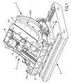
- Figure 1 shows a manipulator 1 for application in the case of a scanning electron microscope.
- the manipulator 1 is made up of a base plate 2 and a manipulation unit 3.
- the base plate 2 has a length of approximately 300 mm and is connected to a portion of the housing of the scanning electron microscope in a manner that will be described later, particularly with reference to figure 2 .
- the weight of the manipulator 1 is approximately 17 kg, whereby the weight of the separate manipulation unit 3 amounts to approximately 7 kg and the weight of the base plate 2 amounts to approximately 10 kg.
- the manipulation unit 3 can be displaced as a whole with respect to the base plate 2 along guides 4a, 4b in the direction of the double arrow 5 through a stroke of circa 150 mm.
- the manipulation unit 3 comprises a first displacement body 6, a swivel body 7, a second displacement body 8 and a sample holder 9.
- the first displacement body 6 is provided on opposite sides of the swivel body 7 with a bent guide, through which a portion of correspondingly formed, externally oriented guide ribs 10 of the swivel body 7 extend.
- the swivel body 7 is provided with a pair of guide bodies 11 a, 11 b on opposite sides of the second displacement body 8, for guided co-operation with guide organs (not further depicted) of the second displacement body 8 that are directed toward the guide bodies 11 a, 11 b.
- translation of the second displacement body 8 with the sample holder 9 is made possible in the longitudinal direction of the guide bodies 11 a, 11 b, through a stroke of circa 150 mm.
- the sample holder which has a disc-like form, can be rotated through a number of complete revolutions about its own central axis, and can also be adjusted in height through circa 30 mm perpendicular to the plane of the disc-like form.
- the sample holder is suitable for holding samples which are destined for further study with the scanning electron microscope concerned.
- manipulator 1 it is possible to manipulate the sample in a total of five degrees of freedom, so as to optimally position and orient the sample in the focus of the electron ray that is generated in the scanning electron microscope.
- manipulator 1 Manipulators of the type of manipulator 1 are known to the skilled artisan, and a detailed description thereof is not necessary in the context of the present invention.
- figure 2 is schematic in nature.
- Figure 2 only depicts the base plate 2 of manipulator 1.
- This base plate 2 is provided at the corner points on its underside with square feet 13a, 13b, 13c, 13d. Near the corner points, bores 14a, 14b, 14c, 14d are present beside the feet 13a, 13b, 13c, 13d. Near the feet 13b and 13c, in the side face 15 of the base plate 2, two horizontally oriented screw-threaded shafts 16a, 16b have been created.
- a basin-like portion 19 is depicted in figure 2 , which portion surrounds the side surfaces and underside of the base plate 2 in the assembled state.
- the housing of the scanning electron microscope does not have to be embodied as a single integral part, but that it can also be made up of a number of rigidly mutually connected components. In that context, it would be permissible, within the bounds of the invention, if the basin-like portion 19, or at least the base 20 thereof, were a part that was rigidly connected to the remaining portion of the housing.
- square raised portions 21 a, 21 b, 21 c, 21 d are provided, which are mutually positioned so as to correspond to feet 13a, 13b, 13c, 13d of base plate 2.
- Vertical screw-threaded shafts 22a, 22b, 22c, 22d are provided centrally in the square raised portions 21 a, 21 b, 21 c, 21 d.
- a first stack 23 of a lower printed circuit board disc 24, a disc-like piezo-electric actuator 25 and an upper printed circuit board disc 26 On each of the four raised portions 21 a, 21 b, 21 c, 21 d is located a first stack 23 of a lower printed circuit board disc 24, a disc-like piezo-electric actuator 25 and an upper printed circuit board disc 26.
- These disc-like bodies 24, 25, 26 are provided in their middles with a through hole, through which a vacuum-compatible screw 27 extends, whose head 28 is sunk into the upper printed circuit board disc 26.
- the screw 27 is turned inside the screw-threaded shaft associated with the relevant raised portion, as a result of which, to a limited extent, a clamping force exists between the lower printed circuit board disc 24, the piezo-electric actuator 25 and the upper printed circuit board disc 26.
- a further centering body 29 is provided in the central hole thereof.
- a second stack 30 is furnished at each of the first stacks 23, against the undersurface of a coupling plate 31 that is present between the base plate 2 and the base 20.
- This coupling plate 31 is provided at its corner points with holes 32a, 32b, 32c (32d is not visible in figure 2 ).
- the second stack 30 consists of a lower printed circuit board disc 34, a piezo-electric sensor 35 and an upper printed circuit board disc 36. These disc-like bodies 34, 35, 36 are clamped against one another by means of a screw 33, which extends through central holes in these disc-like bodies as well as through the relevant hole 32a, 32b, 32c, 32d.
- three raised portions 41 a, 41 b, 41 c are provided around the middle of base 20, three raised portions 41 a, 41 b, 41 c are provided.
- the height of these raised portions 41 a, 41 b, 41 c is equal to the sum of the raised portions 21 a, 21 b, 21 c, 21 d, one stack 23 and one stack 30, so that the upper face of the raised portions 41 a, 41 b, 41 c is substantially at the same vertical level as the upper surface of the four upper printed circuit board discs 36.
- Assembly proceeds as follows.
- the stacks 23 are clamped to the raised portions 21 a, 21 b, 21 c, 21 d by tightening the screws 27 in the associated screw-threaded shafts 22a, 22b, 22c, 22d.
- the tightening force applied hereby in the case of the screws 27 principally serves to correctly and permanently position the various parts of the stack 23 with respect to one another.
- Stacks 30 are clamped against the undersurface of the coupling plate 31 by application of screw/nut combinations 33, 37.
- coupling plate 31 is screwed onto the upper faces of raised portions 41 a, 41 b, 41 c by tightening screws 43a, 43b, 43c in screw-threaded shafts 42a, 42b, 42c in the upper faces of raised portions 41 a, 41 b, 41 c.
- three holes 44 are provided around the center of coupling plate 31, which are mutually positioned so as to correspond to the raised portions 41a, 41b, 41c.
- manipulator 1 is placed on coupling plate 31, whereby the nuts 37 and the extremities of screws 33 extend - with a certain amount of sideways play - within the cavities 38 of the various feet 13a, 13b, 13c, 13d.
- base plate 2 is not supported on only three feet 22a, 22b, 22c, 22d but, instead, on all four feet - as a result of which a desired statically over-determined support situation is achieved at four points of the base plate 2 on the base 20 -
- one of the feet 13a, 13b, 13c, 13d is adjustable in height, in a manner not further depicted, whereby adjustment in height occurs, if necessary, after the base plate 2 has been placed on the coupling plate 31.
- the base plate 2 of the manipulator 1 is positioned in such a manner that bores 14a, 14b, 14c, 14d extend more or less directly above holes 47a, 47b, 47c (47d is not visible) in coupling plate 31 and above screw-threaded shafts 45a, 45b, 45c, 45d in base 20. Thanks to this aligned positioning, it is possible for screw-threaded bodies 46 - with a radial play of the order of approximately 1 to 2 mm - to extend through mutually bores 14a, 14b, 14c, 14d, holes 47a, 47b, 47c, 47d and screw-threaded shafts 45a, 45b, 45c, 45d.
- the undermost extremities of the screw-threaded bodies 46 are hereby screwed tight into the screw-threaded shafts 45a, 45b, 45c, 45d.
- a pressing spring 48 and a washer 49 are fitted around the upper extremity of each screw-threaded body 46.
- a nut 50 is tightened onto the upper extremity of the screw-threaded body 46, so that pressing spring 48 is pre-loaded and the four pressing springs 48 together press the base plate 2 downward with a force of the order of circa 600 N, supplemental to the gravitational force that is already exercised downwards as a result of the weight of the manipulator 1.
- the stiffness of the pressing spring 48 must not be too large, so as to avoid an undesired parallel stiffness across the stacks 23 and 30.
- a rule of thumb for determining an acceptable stiffness of the pressing spring 48 has already been given, whereby it should be noted that a typical eigenfrequency of the resonance (that is to be suppressed) of the manipulator 1 lies in the range between 75 and 1000 Hz. In this manner, one also achieves a situation whereby the stacks 23 and 30 - or, more specifically, the upper face of the upper printed circuit board disc 26 and the lower face of the lower printed circuit board disc 34 - are pressed against one another in good electrical contact.
- coupling plate 31 is relatively small, as a result of the limited thickness thereof (circa 1 mm) and also the mechanical properties of the aluminum from which the coupling plate 31 is manufactured.
- Coupling plate 31 can, therefore, categorically not be considered as being stiff in the direction perpendicular to the plate plane of the coupling plate 31, and shall therefore not introduce any worrying parallel stiffness.
- the coupling plate 31 is, however, stiff in the directions parallel to the plate plane of the coupling plate 31, which is of importance in bearing the sideways forces that arise as a result of displacing the base plate 2 over the coupling plate 31 in the horizontal direction, as will be further described hereunder.
- the size of the downward force produced by the pressing springs 48 and the gravitational force associated with manipulator 1 is not so large as to render no longer possible a small horizontal displacement of the manipulator 1 - or, more specifically, the base plate 2 thereof - by exercising a sideways force. Such a displacement is necessary in order to ensure that the manipulator 1 - or, more specifically, the central axis of the arch-like guide ribs 10a and 10b, about which the swivel body 7 can swivel - is correctly positioned with respect to the electron beam that is generated in the case of the scanning electron microscope.
- manipulator 1 So as to be able to correctly perform this positioning, it is necessary that manipulator 1 be brought into a vacuum environment, as a result of which it is possible to generate an electron beam, whereby this electron beam is subsequently employed in observing what the exact position and orientation of the manipulator 1 are.
- two screw-thread casings 52, 53 are provided in side face 51, through which casings an adjusting organ 54 extends.
- the adjusting organ comprises an engagement portion 140 at whose extremity is located a screw-thread portion 55 intended to engage in screw-threaded shafts 16a, 16b.
- a securing hole 56 Located in this screw-thread portion 55 is a securing hole 56 in which the respective extremities of securing screws 18a, 18b, 18c can engage, so as to secure the adjusting organ 54 in a prescribed rotational position.
- a flat bending part 57 Located directly behind screw-thread portion 55 is a flat bending part 57, which ensures that the bending stiffness of the adjusting organ 54 is limited, at least in the direction parallel to the base 20.
- This flat part 57 is located between the aforementioned screw-thread portion 55 and a further screw-thread portion 58 of the engagement portion 140 that extends within an adjustment bushing 59 of the adjusting organ 54, which is provided around its central axis with an internal screw thread that co-operates with the further screw-thread portion 58.
- Adjusting bushing 59 is provided at one extremity with a screw thread 60 on its outside and at the other extremity with a sealing ring 61.
- Screw thread 60 is destined for engagement co-operation with the internal screw threads of screw-thread casings 52, 53.
- the pitch of screw thread 60, and therefore of the screw thread of the screw-thread casings 52, 53, is chosen so as to be greater than the pitch of the further screw-thread portion 58 and the internal screw thread (not further depicted) in adjustment bushing 59.
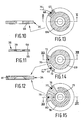
- Stack 30 comprises a piezo-electric sensor 35 in its middle. This sensor is able to measure forces. These forces result in a potential difference between the upper face 64 and the lower face 65 of the sensor 35, which is provided on its upper face 64 and lower face 65 with an evaporated silver layer for electrical contact purposes, so that upper face 64 and lower face 65 can accordingly be regarded as poles.
- the magnitude of this potential difference is a measure of the magnitude of the force or, with a more specific eye to vibrations of the manipulation unit 3, the temporal changes in force exerted on the sensor 35.
- the upper printed circuit board disc 36 and the lower printed circuit board disc 34 are respectively provided at the upper face 64 and the lower face 65 of the sensor 35.
- the upper printed circuit board disc 36 is provided on its lower face with a ring-like conducting track 66 that lies against the upper face 64 of sensor 35.
- a protruding part 67 connects to the ring-like track 66, which part 67 extends to outside the perimeter of sensor 35.
- the potential level at upper face 64 will correspond to the potential level at the location of contact point 68 on the protruding part 67.
- the lower printed circuit board disc is also provided with a ring-like track 69, to which connects a protruding part 70 with contact point 71.
- a small track region 72 is provided, which is isolated from track 69 and which extends outside the external diameter of sensor 35.
- the contact point 73 is connected via an electrically conducting wire 74 to contact point 68 of the upper printed circuit board disc 36, so that contact point 73 will ultimately assume the same potential level as that of upper face 64 of sensor 35. Because of the fact that ring-like track 69 lies against the lower face 65 of sensor 35, contact point 71 will assume the same potential value as that of the lower face 65 of sensor 35.
- the lower face of the lower printed circuit board disc 34 is provided with two conducting tracks that are isolated from one another.
- One of the tracks comprises a ring-like portion 75 to which connects a protruding part 76 with contact point 77.
- the other track comprises an interrupted ring-like portion 78 that substantially surrounds ring-like portion 75, and is also provided with a protruding part 79 with a contact point 80.
- the contact points 71 and 80 are connected to each other right across the main body of the lower printed circuit board disc 34 via a conducting connection 81 ( figure 12 ). A similar sort of connection is realized between the contact points 73 and 77.
- a piezo-electric actuator 25 is centrally provided in stack 23. Such an actuator is able to expand and/or contract in the height direction in reaction to the application of a potential difference between the upper face 82 and the lower face 83 of actuator 25, which faces 82, 83 can be regarded as poles.
- a piezo-electric sensor such as sensor 35, which is connected in series with actuator 25, it is thus possible to realize an active damping system.
- the potential difference between upper face 64 and lower face 65 of piezo-electric sensor 35 (which potential difference is a measure of the force that is exerted on this sensor) is passed on to a control system that processes this potential difference as an input signal and produces an output signal for the actuator 25, which, in reaction hereto, shall alter its height.
- an upper printed circuit board disc 26 and a lower printed circuit board disc 24 are provided on opposite sides.
- This lower printed circuit board disc 24 is provided on its upper face with a ring-like track 84 with protruding part 85 on which a contact point 86 is located.
- the upper printed circuit board disc 26 is provided on its lower face with a ring-like track 87 to which connects a protruding part 88 on which a contact point 89 is provided.
- a small track region 90 which is isolated from ring-like track 87, is located on the lower face of the upper printed circuit board disc 26.
- the track region 90 comprises a contact point 91.
- the track region 90 is located outside the outer perimeter of actuator 25.
- the upper face of the upper printed circuit board disc 26 is provided with two track regions 92, 93 on which respective contact points 94, 95 are located.
- two mutually isolated tracks are provided, one of which comprises a ring-like track portion 96 to which connects a protruding part 97 with a contact point 98, and the other of which comprises an interrupted ring-like track portion 99 that substantially surrounds ring-like track portion 96 and is provided with a protruding part 100 with contact point 101.
- contact point 98 assumes the same potential level as that of the lower face of sensor 35.
- the potential level of contact point 101 assumes the same value as that of the upper face 64 of sensor 35.
- Contact points 86 and 91 are connected to one another via electrically conducting wire 102.
- contact point 91 is connected to contact point 94. In this manner, the potential level of contact point 94 is equal to that of the lower surface 83 of actuator 25.
- Contact points 89 and 95 are also connected to one another by means of a connection similar to connection 81, so that the potential level of contact point 95 corresponds to that of the upper face 82 of actuator 25. In this manner, all relevant potential levels of the actuator and the sensor are available on the upper face of the upper printed circuit board disc 26, which enables very simple installation and simple connection possibilities for the actuator 25 and the sensor 35 via electrically conducting wire.
- a four-core cable 103 is provided with cores 104, 105, 106, 107 and a vacuum-compatible cladding 108.
- the two cores 104 and 105 are together preferably fed through the cladding 108 within an electrical cladding (not further depicted) that, at one of the extremities of cladding 108, is electrically connected to a suitable electrical reference contact point for the whole electrical system - a so-called "electrical earth point".
- the two cores 106 and 107 are together preferably fed through the cladding 108 within a similar electrical cladding (not further depicted) that, in a similar fashion, is connected to a suitable electrical earth point.
- cable 103 is fed through side wall 51 in a gastight manner.
- a plug system for this purpose.
- a control system (not further depicted) that is capable of processing an output signal from the sensor 35 - in the form of a potential difference between cores 104 and 105 - and producing an output signal for the actuator 25 - in the form of a potential difference between the cores 106 and 107 - for the purpose of actively mitigating vibration of the manipulation unit 3.
- the function of actuator allotted to the lower stack 23 and the function of sensor allotted to the upper stack 30 are not limiting. Both functions are, in principle, completely exchangeable, so that the function of sensor can also be allotted to the lower stack 23 and the function of actuator can also be allotted to the upper stack 30.
- vibrations shall occur in two essentially mutually perpendicular principal directions perpendicular to the direction of the normal to the sample holder 9, as a result of the position and orientation of the guides applied in the case of the manipulation unit 3. It is possible to actively oppose these vibrations by only activating each of the four applied actuators 25 via a control unit in sole dependence upon the output signal that the sensor associated with the relevant actuator passes to the control unit.
- An important disadvantage of such a method of damping - in which, consistently, only one single combination of actuator 25 and sensor 35 co-operates with one control unit - is that a disadvantageous torsional deformation of the base plate 2 is unavoidable.
- statically determined support of the base plate 2 at just three points has the considerable disadvantage that a torsional deformation of the base plate 2 is now, in fact, freely possible, and is only limited by the internal torsional stiffness of the base plate 2 itself, without being further impeded by the presence of a fourth support.
- the great risk here i.e. the statically determined support of the base plate 2 at just three points
- the torsional stiffness of this torsionally limp base plate 2 would now determine the first (i.e.
- the first (i.e. lowest) eigenfrequency of the dynamic system demonstrating the perturbing vibrations will be much lower in value if the base plate 2 is supported at three points than if the base plate is supported at four points. In general, in an initial situation, i.e.
- a lower first eigenfrequency of the dynamic system demonstrating the perturbing vibrations will lead to markedly greater amplitudes of the vibrations as a result of excitation via acoustic environmental noise or floor vibrations. Consequently, the final amplitude of the vibrations subsequent to optimal damping of the vibrations - after one or more control units are made effective - will always be smaller if the value of the first eigenfrequency of the dynamic system demonstrating the perturbing vibrations is as high as possible to start off with. Accordingly, the described statically over-determined method of supporting the base plate 2 at four points is highly preferential. In order to achieve this desired statically over-determined method of support during assembly, it is accordingly necessary - as already described above - that one of the feet 13a, 13b, 13c or 13d be adjustable in height in a manner not further elucidated.
- the disadvantage of mechanical crosstalk from actuator to sensor as described above which is the unavoidable consequence of the highly desired over-determined support at four points, is overcome in the case of using four combinations of actuators 25 and sensors 35 by arranging that each, or at least a portion, of the four actuators 25 not be rendered active in dependence upon only the output signal emitted and passed to the control unit by the sensor 35 associated with the actuator 25 concerned, but rather in dependence upon the (sum of) the output signals of at least two sensors.
- the possibility arises of matching the activation of the sensors 25 to one another so that, despite the fact that there are four support points for the base plate 2, the base plate 2 will not be torsionally loaded and, accordingly, will not deform.
- Figure 16 renders a highly schematic plan view of base plate 2. Black dots indicate the four combinations of actuators 25 and sensors 35 at the corner points. In addition, figure 16 indicates the rough location of the center of gravity 109 of the manipulation unit 3, around which two curved arrows 110, 111 symbolize the two mutually perpendicular principal directions of vibration.
- the output signals of the sensors 35 - which, as already mentioned, are a measure of the force registered by the sensors 35 - are respectively indicated by S1, S2, S3 and S4.
- the input signals to the respective actuators 25 are indicated by A1, A2, A3 and A4.
- the associated control system comprises three combination units 112, 113, 114, each of which generates a single output signal by adding together two incoming signals.
- the control system comprises two control units 115, 116, which process incoming signals according to a given frequency-dependent characteristic (referred to as “controller transfer”) and amplification factor (referred to as "gain”) so as to produce output signals.
- control units can be embodied as an analog electronic circuit, or as a digital computer.
- the output signals S1 and S2 are added by combination unit 112, resulting in an output signal SX that functions as an input signal for control unit 115.
- the output signals S2 and S3 are added by combination unit 113, resulting in an output signal SY that functions as an input signal for control unit 116.
- the input signals SX and SY are processed by the respective control units 115, 116 to produce respective output signals AX and AY.
- These signals AX and AY are employed as input signals A1 and A3 for the actuators 25 respectively associated with the first combination and the third combination of an actuator 25 and a sensor 35.
- the signals AX and AY are further added by combination unit 114, resulting in an input signal A2 for the actuator 25 of the second combination.
- each input signal A1, A2, A3 for an actuator 25 is dependent on the force that is measured by the associated sensor 35 as well as that measured by a neighboring sensor 35. It is of importance to note that the actuator 25 and sensor 35 of the fourth combination as a whole remain unused. In the present preferential embodiment, this fourth combination could accordingly be replaced by a passive mechanical support point.
- the force that is measured by the sensor 35 of the second combination, which is located opposite the fourth combination, is, in contrast, employed so as to influence the activity of the actuators 25 of the first, second and third combination. In addition to this, the activity of the sensor 25 of the second combination is dependent upon the forces that are measured by all three sensors 35 of the first, second and third combination.
- each control signal A1, A2, A3, A4 is dependent upon the forces that are measured by each sensor 35 of the four combinations. Vibrations according to arrow 110 are damped by the activity of all four actuators 25, whereby, on the one hand, the actuators 25 of the first and second combination, and, on the other hand, the actuators 25 of the third and fourth combination, will act in pairs in an inverted manner, as a result of which swiveling of the base plate 2 about the swivel axis 131 will occur.
- vibrations according to arrow 111 are damped by the activity of all four actuators 25, whereby, on the one hand, the actuators 25 of the first and fourth combination, and, on the other hand, the actuators 25 of the second and third combination, will act in pairs in an inverted manner, as a result of which swiveling of the base plate 2 about the swivel axis 132 will occur.
- Swivel axes 131 and 132 correspond to the middle lines of base plate 2. Swiveling action of base plate 2 about these swivel axes 131, 132 will not result in plate 2 being torsionally loaded and disturbingly deformed.
- control systems in all sorts of different forms can be applied within the bounds of the invention.
- a rotation of the swivel axes can even be achieved in this manner.
- the exact form of the control system is thus actually made dependent upon one or more parameters of the whole system (for example, the position of the sample holder 9).
Landscapes
- Chemical & Material Sciences (AREA)
- Analytical Chemistry (AREA)
- Control Of Position Or Direction (AREA)
- Electron Beam Exposure (AREA)
- Vibration Prevention Devices (AREA)
Claims (26)
- Teilchenoptische Vorrichtung zum Bestrahlen eines Objekts mit einem Teilchenstrahl, wobei die Einrichtung aufweist: ein Gehäuse (2), in dem sich Positioniereinrichtungen zum Positionieren des Objekts innerhalb des Gehäuses befinden, die einen Bezugskörper (20), der an einem Trägerabschnitt (19) des Gehäuses unterstützt wird, und ein - manipulierbares - kinematisches System mit einem Objektträger (9) aufweisen, um das in dem Objektträger festgehaltene Objekt in mindestens einem Freiheitsgrad bezüglich des Bezugskörpers zu manipulieren, wobei die Einrichtung ferner eine Steuereinrichtung und mindestens eine Kombination aus einem piezoelektrischen Positionsstellglied (25) und einem piezoelektrischen Kraftsensor (35) aufweist, wobei das Stellglied und der Sensor in Reihe angeordnet sind, wodurch die Steuereinrichtung - in Abhängigkeit von mindestens einem Eingangssignal von mindestens einem Sensor - ein Steuersignal zumindest für das mit dem Sensor verbundene Stellglied erzeugt,
dadurch gekennzeichnet, daß die in Reihe angeordneten Elemente Stellglied (25) und Sensor (35) der mindestens einen Kombination zwischen dem Gehäuse (2) und dem Bezugskörper (20) positioniert sind, wobei die Unterstützung des Bezugskörpers (21b) an dem Trägerabschnitt des Gehäuses (13b) über die mindestens eine Kombination erfolgt. - Einrichtung nach Anspruch 1, dadurch gekennzeichnet, daß mindestens drei Kombinationen vorzugsweise nahe einer Umfangskante des Bezugskörpers positioniert sind.
- Einrichtung nach Anspruch 1 oder 2, dadurch gekennzeichnet, daß mindestens drei Kombinationen jeweils in der Nähe von mindestens drei Eckpunkten des Bezugskörpers positioniert sind.
- Einrichtung nach Anspruch 2 oder 3, dadurch gekennzeichnet, daß zwei Verbindungslinien zwischen den Positionen von mindestens drei Kombinationen einander im rechten Winkel schneiden.
- Einrichtung nach einem der vorstehenden Ansprüche, dadurch gekennzeichnet, daß mindestens ein Trägerelement zwischen dem Gehäuse und dem Bezugskörper positioniert ist, und daß die Unterstützung des Bezugskörpers an dem Trägerabschnitt des Gehäuses - ergänzend zu der Unterstützung über die mindestens eine Kombination - zusätzlich über dieses Trägerelement erfolgt, wodurch die Summe der Anzahl von Trägerelementen und der Anzahl von Kombinationen mindestens gleich vier ist.
- Einrichtung nach Anspruch 5, dadurch gekennzeichnet, daß das mindestens eine Trägerelement mindestens eine weitere Kombination aus einem piezoelektrischen Positionsstellglied und einem piezoelektrischen Kraftsensor aufweist, wobei das Stellglied und der Kraftsensor in Reihe angeordnet sind, wobei mindestens eine weitere Kombination die mindestens eine Kombination ergänzt, wodurch die Summe der Anzahl von Kombinationen und der Anzahl weiterer Kombinationen mindestens gleich vier ist.
- Einrichtung nach Anspruch 5 oder 6, dadurch gekennzeichnet, daß die Steuereinrichtung eine erste Kombinationseinrichtung zum Zweck der Kombination mindestens eines ersten Eingangssignals mit einem zweiten Eingangssignal - von mindestens einem ersten Sensor bzw. einem zweiten Sensor - zu einem ersten kombinierten Eingangssignal aufweist, in Abhängigkeit von dem die Steuereinrichtung ein erstes gemeinsames Steuersignal für die entsprechenden Stellglieder erzeugt, die zumindest sowohl mit dem ersten Sensor als auch mit dem zweiten Sensor verbunden sind.
- Einrichtung nach Anspruch 7, dadurch gekennzeichnet, daß die Steuereinrichtung eine zweite Kombinationseinrichtung zum Zweck der Kombination mindestens des zweiten Eingangssignals mit einem dritten Eingangssignal von mindestens dem zweiten Sensor bzw. einem dritten Sensor zu einem zweiten kombinierten Eingangssignal aufweist, in Abhängigkeit von dem die Steuereinrichtung ein zweites gemeinsames Steuersignal für die entsprechenden Stellglieder erzeugt, die zumindest mit dem zweiten Sensor und dem dritten Sensor verbunden sind, wobei die Steuereinrichtung eine dritte Kombinationseinrichtung zum Zweck der Kombination des ersten gemeinsamen Steuersignals und des zweiten gemeinsamen Steuersignals zu einem kombinierten gemeinsamen Steuersignal für das zweite Stellglied aufweist.
- Einrichtung nach Anspruch 7, dadurch gekennzeichnet, daß die erste Kombinationseinrichtung so ausgeführt wird, daß sie zumindest das erste Eingangssignal, das zweite Eingangssignal, ein drittes Eingangssignal und ein viertes Eingangssignal - von zumindest dem ersten Sensor, dem zweiten Sensor, einem dritten Sensor bzw. einem vierten Sensor - zu einem ersten kombinierten Eingangssignal kombiniert, in Abhängigkeit von dem die Steuereinrichtung das erste gemeinsame Steuersignal für die Stellglieder erzeugt, die dem ersten Sensor, dem zweiten Sensor, dem dritten Sensor und dem vierten Sensor zugeordnet sind.
- Einrichtung nach Anspruch 7 mit den Merkmalen der Ansprüche 8 und 9, dadurch gekennzeichnet, daß die zweite Kombinationseinrichtung so ausgeführt wird, daß sie zumindest das erste Eingangssignal, das zweite Eingangssignal, das dritte Eingangssignal und das vierte Eingangssignal - von zumindest dem ersten Sensor, dem zweiten Sensor, dem dritten Sensor bzw. dem vierten Sensor - auf eine andere Weise als die, in der die erste Kombinationseinrichtung das erste Eingangssignal, das zweite Eingangssignal, das dritte Eingangssignal und das vierte Eingangssignal zu dem ersten kombinierten Eingangssignal vereinigt, zu dem zweiten kombinierten Eingangssignal kombiniert, wobei die Steuereinrichtung in Abhängigkeit von dem zweiten kombinierten Eingangssignal das zweite gemeinsame Steuersignal für die Stellglieder erzeugt, die mit dem ersten Sensor, dem zweiten Sensor, dem dritten Sensor bzw. dem vierten Sensor verbunden sind.
- Einrichtung nach einem der vorstehenden Ansprüche, dadurch gekennzeichnet, daß zwischen den in Reihe angeordneten Elementen Stellglied und Sensor der mindestens einen Kombination einerseits und dem Bezugskörper andererseits ein Zwischenkörper vorgesehen ist.
- Einrichtung nach Anspruch 11, dadurch gekennzeichnet, daß der Zwischenkörper plattenförmig ist.
- Einrichtung nach Anspruch 12, dadurch gekennzeichnet, daß der plattenförmige Zwischenkörper aus Aluminium besteht und eine Dicke aufweist, die kleiner ist als 10% der kleinsten Hauptabmessung des plattenförmigen Zwischenkörpers.
- Einrichtung nach einem der Ansprüche 12 bis 13, dadurch gekennzeichnet, daß die Einrichtung mit Justiervorrichtungen zum Verschieben des Bezugskörpers in einer zu dem plattenförmigen Zwischenkörper parallelen Richtung ausgestattet ist.
- Einrichtung nach Anspruch 14, dadurch gekennzeichnet, daß die Justiervorrichtungen so ausgeführt werden, daß der Bezugskörper in drei Freiheitsgraden verschoben werden kann.
- Einrichtung nach einem der Ansprüche 11 bis 15, dadurch gekennzeichnet, daß der Bezugskörper an dem Zwischenkörper mit einer Kraft abgestützt wird, die im Bereich zwischen dem zweifachen und dem zwanzigfachen Gewicht der zu tragenden Positioniereinrichtungen liegt.
- Einrichtung nach Anspruch 16, dadurch gekennzeichnet, daß Federeinrichtungen vorgesehen sind, um den Bezugskörper und den Zwischenkörper gegeneinander zu drücken.
- Einrichtung nach Anspruch 17, dadurch gekennzeichnet, daß die folgende Beziehung gilt:

wobei fpos die Eigenfrequenz der Positioniereinrichtungen ist, deren Unterdrückung angestrebt wird, und fspring die Eigenfrequenz des gedachten Systems ist, das entstehen würde, wenn die kombinierte Masse des Bezugskörpers plus der Positioniereinrichtungen bei fehlendem Kombinations- oder Trägerelement von den Federeinrichtungen allein zu unterstützen wäre. - Einrichtung nach einem der vorstehenden Ansprüche, dadurch gekennzeichnet, daß jedes Stellglied jeweils zwischen einem ersten Stellgliedleitungskörper, der sich im Leitungskontakt mit einem ersten Stellgliedpol befindet, und einem zweiten Stellgliedleitungskörper im Leitungskontakt mit einem zweiten Stellgliedpol eingespannt ist, wobei sich der erste Stellgliedleitungskörper und der zweite Stellgliedleitungskörper im Leitungskontakt mit der Steuereinrichtung befinden.
- Einrichtung nach einem der vorstehenden Ansprüche, dadurch gekennzeichnet, daß jeder Sensor jeweils zwischen einem ersten Sensorleitungskörper, der sich im Leitungskontakt mit einem ersten Sensorpol des Sensors befindet, und einem zweiten Sensorleitungskörper im Leitungskontakt mit einem zweiten Sensorpol des Sensors eingespannt ist, wobei sich der erste Sensorleitungskörper und der zweite Sensorleitungskörper im Leitungskontakt mit der Steuereinrichtung befinden.
- Einrichtung nach Anspruch 19 oder 20, dadurch gekennzeichnet, daß das Stellglied mit zugehörigen Leitungskörpern und/oder der Sensor mit zugehörigen Leitungskörpern mit gemeinsamen Verbindungslöchern versehen sind, die zusammen ein Durchgangsloch bilden, durch das ein Zugwerkzeug hindurchgeht, um das Stellglied bzw. den Sensor zwischen den zugehörigen Leitungskörpern einzuspannen.
- Einrichtung nach Anspruch 19, 20 oder 21, dadurch gekennzeichnet, daß einer der beiden dem Stellglied oder dem Sensor einer Kombination zugeordneter Leitungskörper mit zwei Kontaktpunkten versehen ist, die sich im Leitungskontakt mit beiden Polen des zugehörigen Stellglieds befinden.
- Einrichtung nach Anspruch 22, dadurch gekennzeichnet, daß einer der vier dem Stellglied und dem Sensor einer Kombination zugeordneter Leitungskörper mit vier Kontaktpunkten versehen ist, die sich im Leitungskontakt mit beiden Polen des Stellglieds und des Sensors befinden.
- Einrichtung nach Anspruch 20, 21, 22 oder 23, dadurch gekennzeichnet, daß die zwischen dem Stellglied und dem Sensor einer Kombination angeordneter Leitungskörper an den einander zugewandten Seiten mit Kontaktpunkten versehen sind, die leitend miteinander verbunden sind.
- Einrichtung nach Anspruch 24, dadurch gekennzeichnet, daß zumindest ein Teil der Leitungskörper - an mindestens einer Außenfläche - mit mindestens einer isolierten Leiterbahn für direkten elektrischen Kontakt mit einem Pol entweder eines Stellglieds oder eines Sensors oder mit einem Kontaktpunkt oder einer Leiterbahn eines Leitungskörpers versehen ist.
- Einrichtung nach einem der Ansprüche 19 bis 25, dadurch gekennzeichnet, daß die mit einer Kombination aus einem Stellglied und einem Sensor verbundenen Leitungskörper leitend mit Leitern verbunden sind, die aus dem Gehäuse nach außen führen.
Applications Claiming Priority (2)
| Application Number | Priority Date | Filing Date | Title |
|---|---|---|---|
| NL1022886 | 2003-03-10 | ||
| NL1022886A NL1022886C2 (nl) | 2003-03-10 | 2003-03-10 | Deeltjes optische inrichting voor het bestralen van een object. |
Publications (3)
| Publication Number | Publication Date |
|---|---|
| EP1458005A2 EP1458005A2 (de) | 2004-09-15 |
| EP1458005A3 EP1458005A3 (de) | 2005-05-04 |
| EP1458005B1 true EP1458005B1 (de) | 2008-08-13 |
Family
ID=32768730
Family Applications (1)
| Application Number | Title | Priority Date | Filing Date |
|---|---|---|---|
| EP04075506A Expired - Lifetime EP1458005B1 (de) | 2003-03-10 | 2004-02-17 | Teilchenoptischer Apparat zur Bestrahlung eines Objekts |
Country Status (6)
| Country | Link |
|---|---|
| US (1) | US7091497B2 (de) |
| EP (1) | EP1458005B1 (de) |
| JP (1) | JP4815103B2 (de) |
| CN (1) | CN100526984C (de) |
| DE (1) | DE602004015657D1 (de) |
| NL (1) | NL1022886C2 (de) |
Families Citing this family (11)
| Publication number | Priority date | Publication date | Assignee | Title |
|---|---|---|---|---|
| EP1816273A1 (de) | 2006-02-01 | 2007-08-08 | FEI Company | Gehäuse für die akustische Isolierung eines Geräts in besagtem Gehäuse |
| US7936443B2 (en) * | 2006-05-09 | 2011-05-03 | Asml Netherlands B.V. | Lithographic apparatus and device manufacturing method |
| US8598524B2 (en) * | 2006-06-07 | 2013-12-03 | Fei Company | Slider bearing for use with an apparatus comprising a vacuum chamber |
| CN101461026B (zh) * | 2006-06-07 | 2012-01-18 | Fei公司 | 与包含真空室的装置一起使用的滑动轴承 |
| US8908144B2 (en) * | 2006-09-27 | 2014-12-09 | Asml Netherlands B.V. | Lithographic apparatus and device manufacturing method |
| US8044373B2 (en) * | 2007-06-14 | 2011-10-25 | Asml Netherlands B.V. | Lithographic apparatus and device manufacturing method |
| DE102008033369A1 (de) * | 2008-07-08 | 2010-01-14 | E.G.O. Elektro-Gerätebau GmbH | Bedieneinrichtung für ein Elektrogerät und Auswerteverfahren für diese Bedieneinrichtung |
| NL2005701A (en) * | 2009-12-22 | 2011-06-23 | Asml Netherlands Bv | Active mount, lithographic apparatus comprising such active mount and method for tuning such active mount. |
| JP6633986B2 (ja) * | 2016-07-20 | 2020-01-22 | 株式会社日立ハイテクノロジーズ | 荷電粒子線装置 |
| CN107062828B (zh) * | 2017-06-09 | 2020-04-10 | 京东方科技集团股份有限公司 | 一种真空干燥装置 |
| CN111391337B (zh) * | 2020-03-20 | 2021-12-10 | 海盐沛泓汽车零部件有限公司 | 一种尼龙自锁螺母的尼龙圈套嵌装置 |
Family Cites Families (13)
| Publication number | Priority date | Publication date | Assignee | Title |
|---|---|---|---|---|
| JPH0614789B2 (ja) * | 1984-06-25 | 1994-02-23 | 株式会社東芝 | テーブル微動方法およびこの方法を用いた微動装置 |
| US4928030A (en) * | 1988-09-30 | 1990-05-22 | Rockwell International Corporation | Piezoelectric actuator |
| CA2081094A1 (en) * | 1992-02-18 | 1993-08-19 | Gordon Walter Culp | Walking toothed actuator |
| EP0592030B1 (de) * | 1992-10-02 | 1998-05-20 | Koninklijke Philips Electronics N.V. | Elektromechanische Verschiebevorrichtung und geeigneter Aktuator zur Verwendung in einer derartigen Verschiebevorrichtung |
| JPH07201298A (ja) * | 1993-12-28 | 1995-08-04 | Jeol Ltd | 平板状試料の移動ステージ |
| US6154000A (en) * | 1994-09-07 | 2000-11-28 | Omnitek Research & Development, Inc. | Apparatus for providing a controlled deflection and/or actuator apparatus |
| AU1172699A (en) * | 1997-11-18 | 1999-06-07 | Nikon Corporation | Vibration eliminator, aligner and projection exposure method |
| WO1999066501A1 (en) * | 1998-06-15 | 1999-12-23 | Seagate Technology Llc | Disc drive having charge feedback driven microactuator |
| JP2001050334A (ja) * | 1999-08-05 | 2001-02-23 | Fujita Corp | アクティブ型除振装置 |
| JP2001093798A (ja) * | 1999-09-20 | 2001-04-06 | Canon Inc | ステージ装置 |
| US6768124B2 (en) * | 1999-10-19 | 2004-07-27 | Nikon Corporation | Reticle-focus detector, and charged-particle-beam microlithography apparatus and methods comprising same |
| JP3961311B2 (ja) * | 2001-01-19 | 2007-08-22 | エーエスエムエル ネザーランズ ビー.ブイ. | リソグラフィ装置およびデバイスの製造方法 |
| EP1225482A1 (de) * | 2001-01-19 | 2002-07-24 | ASML Netherlands B.V. | Lithographischer Apparat und Verfahren zur Herstellung einer Vorrichtung |
-
2003
- 2003-03-10 NL NL1022886A patent/NL1022886C2/nl not_active IP Right Cessation
-
2004
- 2004-02-17 DE DE602004015657T patent/DE602004015657D1/de not_active Expired - Lifetime
- 2004-02-17 EP EP04075506A patent/EP1458005B1/de not_active Expired - Lifetime
- 2004-03-08 US US10/795,759 patent/US7091497B2/en not_active Expired - Lifetime
- 2004-03-09 JP JP2004065811A patent/JP4815103B2/ja not_active Expired - Fee Related
- 2004-03-10 CN CNB2004100352219A patent/CN100526984C/zh not_active Expired - Fee Related
Also Published As
| Publication number | Publication date |
|---|---|
| CN1550901A (zh) | 2004-12-01 |
| JP2004273459A (ja) | 2004-09-30 |
| US7091497B2 (en) | 2006-08-15 |
| EP1458005A3 (de) | 2005-05-04 |
| EP1458005A2 (de) | 2004-09-15 |
| DE602004015657D1 (de) | 2008-09-25 |
| NL1022886C2 (nl) | 2004-09-14 |
| CN100526984C (zh) | 2009-08-12 |
| JP4815103B2 (ja) | 2011-11-16 |
| US20040178354A1 (en) | 2004-09-16 |
Similar Documents
| Publication | Publication Date | Title |
|---|---|---|
| EP1458005B1 (de) | Teilchenoptischer Apparat zur Bestrahlung eines Objekts | |
| KR100399812B1 (ko) | 스테이지용진동방지장치 | |
| US8729467B2 (en) | Charged particle radiation device | |
| TWI687961B (zh) | 電子束檢測設備載物台定位 | |
| JP2001027280A (ja) | アクティブ除振装置 | |
| US6089525A (en) | Six axis active vibration isolation and payload reaction force compensation system | |
| JP6676407B2 (ja) | 荷電粒子線装置、及び荷電粒子線装置用制振ダンパ | |
| US3835320A (en) | Particle-beam device equipped with means for attenuating mechanical movements | |
| JP5947128B2 (ja) | 帯電粒子を用いて試料を結像、検査又は処理する装置及び方法 | |
| JP2016114141A (ja) | アクティブ除振装置 | |
| KR102425943B1 (ko) | 시편을 검사하는 하전 입자 빔 디바이스, 대물 렌즈 모듈, 전극 디바이스, 및 방법 | |
| KR20220081279A (ko) | 능동형 제진 시스템 | |
| US20200105499A1 (en) | Charged particle beam irradiation apparatus | |
| TWI744591B (zh) | 制振系統以及具備該制振系統的光學裝置 | |
| US11740649B2 (en) | Multidirectional input device | |
| JP2018005975A (ja) | 荷電粒子線装置に取り付けられる振動抑制機構、及び荷電粒子線装置 | |
| JPH094677A (ja) | 防振方法 | |
| CN114577250A (zh) | 带缓冲器的测量设备和保护测量设备免受震动的方法 | |
| WO2021205526A1 (ja) | 荷電粒子銃、荷電粒子ビームシステム、およびロックナット | |
| JPH07310779A (ja) | アクティブ除振装置 | |
| JPH0973872A (ja) | 荷電粒子ビーム装置 | |
| WO2023120392A1 (en) | Electronic instrument, electronic cymbal set, and electronic hi-hat cymbals | |
| JPH04304985A (ja) | ロボット支持装置 | |
| JP2002181123A (ja) | アクティブ除振装置 | |
| JP5276548B2 (ja) | アクティブ防振方法及びこれに用いる防振装置 |
Legal Events
| Date | Code | Title | Description |
|---|---|---|---|
| PUAI | Public reference made under article 153(3) epc to a published international application that has entered the european phase |
Free format text: ORIGINAL CODE: 0009012 |
|
| 17P | Request for examination filed |
Effective date: 20040217 |
|
| AK | Designated contracting states |
Kind code of ref document: A2 Designated state(s): AT BE BG CH CY CZ DE DK EE ES FI FR GB GR HU IE IT LI LU MC NL PT RO SE SI SK TR |
|
| AX | Request for extension of the european patent |
Extension state: AL LT LV MK |
|
| PUAL | Search report despatched |
Free format text: ORIGINAL CODE: 0009013 |
|
| AK | Designated contracting states |
Kind code of ref document: A3 Designated state(s): AT BE BG CH CY CZ DE DK EE ES FI FR GB GR HU IE IT LI LU MC NL PT RO SE SI SK TR |
|
| AX | Request for extension of the european patent |
Extension state: AL LT LV MK |
|
| RIC1 | Information provided on ipc code assigned before grant |
Ipc: 7H 01J 37/20 A Ipc: 7H 01L 21/68 B Ipc: 7G 03F 7/20 B |
|
| AKX | Designation fees paid |
Designated state(s): CZ DE FR GB NL |
|
| GRAP | Despatch of communication of intention to grant a patent |
Free format text: ORIGINAL CODE: EPIDOSNIGR1 |
|
| GRAS | Grant fee paid |
Free format text: ORIGINAL CODE: EPIDOSNIGR3 |
|
| GRAA | (expected) grant |
Free format text: ORIGINAL CODE: 0009210 |
|
| AK | Designated contracting states |
Kind code of ref document: B1 Designated state(s): CZ DE FR GB NL |
|
| REG | Reference to a national code |
Ref country code: GB Ref legal event code: FG4D |
|
| REF | Corresponds to: |
Ref document number: 602004015657 Country of ref document: DE Date of ref document: 20080925 Kind code of ref document: P |
|
| PG25 | Lapsed in a contracting state [announced via postgrant information from national office to epo] |
Ref country code: NL Free format text: LAPSE BECAUSE OF FAILURE TO SUBMIT A TRANSLATION OF THE DESCRIPTION OR TO PAY THE FEE WITHIN THE PRESCRIBED TIME-LIMIT Effective date: 20080813 |
|
| PG25 | Lapsed in a contracting state [announced via postgrant information from national office to epo] |
Ref country code: CZ Free format text: LAPSE BECAUSE OF FAILURE TO SUBMIT A TRANSLATION OF THE DESCRIPTION OR TO PAY THE FEE WITHIN THE PRESCRIBED TIME-LIMIT Effective date: 20080813 |
|
| PLBE | No opposition filed within time limit |
Free format text: ORIGINAL CODE: 0009261 |
|
| STAA | Information on the status of an ep patent application or granted ep patent |
Free format text: STATUS: NO OPPOSITION FILED WITHIN TIME LIMIT |
|
| 26N | No opposition filed |
Effective date: 20090514 |
|
| REG | Reference to a national code |
Ref country code: FR Ref legal event code: PLFP Year of fee payment: 13 |
|
| REG | Reference to a national code |
Ref country code: FR Ref legal event code: PLFP Year of fee payment: 14 |
|
| REG | Reference to a national code |
Ref country code: FR Ref legal event code: PLFP Year of fee payment: 15 |
|
| PGFP | Annual fee paid to national office [announced via postgrant information from national office to epo] |
Ref country code: GB Payment date: 20190213 Year of fee payment: 16 Ref country code: FR Payment date: 20190111 Year of fee payment: 16 Ref country code: DE Payment date: 20190205 Year of fee payment: 16 |
|
| REG | Reference to a national code |
Ref country code: DE Ref legal event code: R119 Ref document number: 602004015657 Country of ref document: DE |
|
| GBPC | Gb: european patent ceased through non-payment of renewal fee |
Effective date: 20200217 |
|
| PG25 | Lapsed in a contracting state [announced via postgrant information from national office to epo] |
Ref country code: FR Free format text: LAPSE BECAUSE OF NON-PAYMENT OF DUE FEES Effective date: 20200229 Ref country code: GB Free format text: LAPSE BECAUSE OF NON-PAYMENT OF DUE FEES Effective date: 20200217 Ref country code: DE Free format text: LAPSE BECAUSE OF NON-PAYMENT OF DUE FEES Effective date: 20200901 |