EP1457698A2 - Ausrücklager - Google Patents
Ausrücklager Download PDFInfo
- Publication number
- EP1457698A2 EP1457698A2 EP04004936A EP04004936A EP1457698A2 EP 1457698 A2 EP1457698 A2 EP 1457698A2 EP 04004936 A EP04004936 A EP 04004936A EP 04004936 A EP04004936 A EP 04004936A EP 1457698 A2 EP1457698 A2 EP 1457698A2
- Authority
- EP
- European Patent Office
- Prior art keywords
- sealing
- bearing ring
- sealing cap
- bearing
- release bearing
- Prior art date
- Legal status (The legal status is an assumption and is not a legal conclusion. Google has not performed a legal analysis and makes no representation as to the accuracy of the status listed.)
- Granted
Links
- 238000007789 sealing Methods 0.000 claims abstract description 176
- 150000001875 compounds Chemical class 0.000 claims abstract description 14
- 238000000034 method Methods 0.000 claims abstract description 11
- 239000011248 coating agent Substances 0.000 claims description 14
- 238000000576 coating method Methods 0.000 claims description 14
- 239000000565 sealant Substances 0.000 claims description 9
- 238000005520 cutting process Methods 0.000 claims description 4
- 238000005096 rolling process Methods 0.000 claims description 4
- 239000007788 liquid Substances 0.000 claims description 3
- 239000006228 supernatant Substances 0.000 claims description 3
- 230000005540 biological transmission Effects 0.000 claims description 2
- 238000002485 combustion reaction Methods 0.000 claims description 2
- 238000009434 installation Methods 0.000 claims description 2
- 229920002379 silicone rubber Polymers 0.000 claims description 2
- 239000004945 silicone rubber Substances 0.000 claims description 2
- QBWKPGNFQQJGFY-QLFBSQMISA-N 3-[(1r)-1-[(2r,6s)-2,6-dimethylmorpholin-4-yl]ethyl]-n-[6-methyl-3-(1h-pyrazol-4-yl)imidazo[1,2-a]pyrazin-8-yl]-1,2-thiazol-5-amine Chemical compound N1([C@H](C)C2=NSC(NC=3C4=NC=C(N4C=C(C)N=3)C3=CNN=C3)=C2)C[C@H](C)O[C@H](C)C1 QBWKPGNFQQJGFY-QLFBSQMISA-N 0.000 description 10
- 229940125846 compound 25 Drugs 0.000 description 10
- 239000000314 lubricant Substances 0.000 description 8
- 238000005304 joining Methods 0.000 description 3
- 238000004519 manufacturing process Methods 0.000 description 2
- 239000000853 adhesive Substances 0.000 description 1
- 230000001070 adhesive effect Effects 0.000 description 1
- 239000011324 bead Substances 0.000 description 1
- 230000009286 beneficial effect Effects 0.000 description 1
- 230000015572 biosynthetic process Effects 0.000 description 1
- 238000010276 construction Methods 0.000 description 1
- 238000005260 corrosion Methods 0.000 description 1
- 230000007797 corrosion Effects 0.000 description 1
- 230000001419 dependent effect Effects 0.000 description 1
- 230000000694 effects Effects 0.000 description 1
- 239000012530 fluid Substances 0.000 description 1
- 238000010438 heat treatment Methods 0.000 description 1
- 239000012535 impurity Substances 0.000 description 1
- 230000007774 longterm Effects 0.000 description 1
- 239000002184 metal Substances 0.000 description 1
- 229910001092 metal group alloy Inorganic materials 0.000 description 1
- 239000006223 plastic coating Substances 0.000 description 1
- 230000002028 premature Effects 0.000 description 1
- 239000007921 spray Substances 0.000 description 1
- 238000005507 spraying Methods 0.000 description 1
Images


Classifications
-
- F—MECHANICAL ENGINEERING; LIGHTING; HEATING; WEAPONS; BLASTING
- F16—ENGINEERING ELEMENTS AND UNITS; GENERAL MEASURES FOR PRODUCING AND MAINTAINING EFFECTIVE FUNCTIONING OF MACHINES OR INSTALLATIONS; THERMAL INSULATION IN GENERAL
- F16C—SHAFTS; FLEXIBLE SHAFTS; ELEMENTS OR CRANKSHAFT MECHANISMS; ROTARY BODIES OTHER THAN GEARING ELEMENTS; BEARINGS
- F16C33/00—Parts of bearings; Special methods for making bearings or parts thereof
- F16C33/72—Sealings
- F16C33/76—Sealings of ball or roller bearings
- F16C33/78—Sealings of ball or roller bearings with a diaphragm, disc, or ring, with or without resilient members
- F16C33/7886—Sealings of ball or roller bearings with a diaphragm, disc, or ring, with or without resilient members mounted outside the gap between the inner and outer races, e.g. sealing rings mounted to an end face or outer surface of a race
-
- F—MECHANICAL ENGINEERING; LIGHTING; HEATING; WEAPONS; BLASTING
- F16—ENGINEERING ELEMENTS AND UNITS; GENERAL MEASURES FOR PRODUCING AND MAINTAINING EFFECTIVE FUNCTIONING OF MACHINES OR INSTALLATIONS; THERMAL INSULATION IN GENERAL
- F16C—SHAFTS; FLEXIBLE SHAFTS; ELEMENTS OR CRANKSHAFT MECHANISMS; ROTARY BODIES OTHER THAN GEARING ELEMENTS; BEARINGS
- F16C33/00—Parts of bearings; Special methods for making bearings or parts thereof
- F16C33/72—Sealings
- F16C33/76—Sealings of ball or roller bearings
- F16C33/768—Sealings of ball or roller bearings between relatively stationary parts, i.e. static seals
-
- F—MECHANICAL ENGINEERING; LIGHTING; HEATING; WEAPONS; BLASTING
- F16—ENGINEERING ELEMENTS AND UNITS; GENERAL MEASURES FOR PRODUCING AND MAINTAINING EFFECTIVE FUNCTIONING OF MACHINES OR INSTALLATIONS; THERMAL INSULATION IN GENERAL
- F16C—SHAFTS; FLEXIBLE SHAFTS; ELEMENTS OR CRANKSHAFT MECHANISMS; ROTARY BODIES OTHER THAN GEARING ELEMENTS; BEARINGS
- F16C33/00—Parts of bearings; Special methods for making bearings or parts thereof
- F16C33/72—Sealings
- F16C33/76—Sealings of ball or roller bearings
- F16C33/78—Sealings of ball or roller bearings with a diaphragm, disc, or ring, with or without resilient members
- F16C33/7816—Details of the sealing or parts thereof, e.g. geometry, material
- F16C33/783—Details of the sealing or parts thereof, e.g. geometry, material of the mounting region
-
- F—MECHANICAL ENGINEERING; LIGHTING; HEATING; WEAPONS; BLASTING
- F16—ENGINEERING ELEMENTS AND UNITS; GENERAL MEASURES FOR PRODUCING AND MAINTAINING EFFECTIVE FUNCTIONING OF MACHINES OR INSTALLATIONS; THERMAL INSULATION IN GENERAL
- F16D—COUPLINGS FOR TRANSMITTING ROTATION; CLUTCHES; BRAKES
- F16D23/00—Details of mechanically-actuated clutches not specific for one distinct type
- F16D23/12—Mechanical clutch-actuating mechanisms arranged outside the clutch as such
- F16D23/14—Clutch-actuating sleeves or bearings; Actuating members directly connected to clutch-actuating sleeves or bearings
-
- F—MECHANICAL ENGINEERING; LIGHTING; HEATING; WEAPONS; BLASTING
- F16—ENGINEERING ELEMENTS AND UNITS; GENERAL MEASURES FOR PRODUCING AND MAINTAINING EFFECTIVE FUNCTIONING OF MACHINES OR INSTALLATIONS; THERMAL INSULATION IN GENERAL
- F16C—SHAFTS; FLEXIBLE SHAFTS; ELEMENTS OR CRANKSHAFT MECHANISMS; ROTARY BODIES OTHER THAN GEARING ELEMENTS; BEARINGS
- F16C19/00—Bearings with rolling contact, for exclusively rotary movement
- F16C19/02—Bearings with rolling contact, for exclusively rotary movement with bearing balls essentially of the same size in one or more circular rows
- F16C19/14—Bearings with rolling contact, for exclusively rotary movement with bearing balls essentially of the same size in one or more circular rows for both radial and axial load
- F16C19/16—Bearings with rolling contact, for exclusively rotary movement with bearing balls essentially of the same size in one or more circular rows for both radial and axial load with a single row of balls
- F16C19/163—Bearings with rolling contact, for exclusively rotary movement with bearing balls essentially of the same size in one or more circular rows for both radial and axial load with a single row of balls with angular contact
-
- F—MECHANICAL ENGINEERING; LIGHTING; HEATING; WEAPONS; BLASTING
- F16—ENGINEERING ELEMENTS AND UNITS; GENERAL MEASURES FOR PRODUCING AND MAINTAINING EFFECTIVE FUNCTIONING OF MACHINES OR INSTALLATIONS; THERMAL INSULATION IN GENERAL
- F16C—SHAFTS; FLEXIBLE SHAFTS; ELEMENTS OR CRANKSHAFT MECHANISMS; ROTARY BODIES OTHER THAN GEARING ELEMENTS; BEARINGS
- F16C2361/00—Apparatus or articles in engineering in general
- F16C2361/43—Clutches, e.g. disengaging bearing
-
- F—MECHANICAL ENGINEERING; LIGHTING; HEATING; WEAPONS; BLASTING
- F16—ENGINEERING ELEMENTS AND UNITS; GENERAL MEASURES FOR PRODUCING AND MAINTAINING EFFECTIVE FUNCTIONING OF MACHINES OR INSTALLATIONS; THERMAL INSULATION IN GENERAL
- F16D—COUPLINGS FOR TRANSMITTING ROTATION; CLUTCHES; BRAKES
- F16D2300/00—Special features for couplings or clutches
- F16D2300/08—Details or arrangements of sealings not provided for in group F16D3/84
Definitions
- the present invention relates to a release bearing for an actuating device of switch disconnectors, which are preferably used in vehicles between an internal combustion engine and a gear change transmission is.
- the release bearing which is preferably designed as an inclined shoulder bearing includes a circumferential, outer bearing ring and a torsionally rigid inner one Bearing ring, between which run in races and inserted in a cage Rolling elements are arranged to seal an interior of the Release bearing includes the release bearing sealing caps that are attached to a bearing ring attached, observing an annular gap to the associated other Bearing ring are guided.
- Each bearing ring is still radial with one provided a longitudinal axis of the release bearing aligned flange the release bearing on one side with an axially displaceable component, the actuating device and each other with one of the shifting clutch associated spring means cooperates
- a release bearing of the aforementioned type is for example from DE 197 16 218 A1 known.
- the circular interior of this release bearing the rolling element is sealed on both sides.
- the facing side is a holding element which acts as a sealing element intended.
- This includes a radial leg that is circular Open space protrudes, which on both sides of radially extending Thrust flanges of the bearing rings is limited.
- the radial leg of the holding element is in compliance with an annular gap to the associated outer, circumferential bearing ring guided.
- the known Release bearing a sealing cap attached to the rigid inner ring, whose radial leg is attached to the inner bearing ring and their associated cylindrical leg the circumferential outer bearing ring radially spaced partially encloses.
- the at a defined distance from the outside Bearing ring running sealing cap does not provide effective protection against a lubricant leak from the inside of the release bearing or entry of Impurities in the release bearing
- the sealing cap to fix the circumferential outer bearing ring. Furthermore, the invention closes a sealing compound which in an axial groove formed as a sealing zone
- the sealing cap is fluid and can be hardened permanently Measure effectively prevents lubricant from escaping from the interior of the release bearing, which is advantageous to the function and thus to the Life of the release bearing affects.
- the effectiveness of the seal allows the one brought into the release bearing Lubricant amount can be advantageously reduced because of a Leakage-related loss of lubricant does not occur
- the amount of lubricant required in the release bearing can be precisely determined using Long-term attempts are determined and thus a failure of the release bearing due to a loss of lubricant can be prevented.
- the precisely meterable Reduced amount of lubricant compared to previous release bearings also has a beneficial effect on the heating of the release bearing and thus also reduces premature failure of the release bearing.
- the invention according to claim 15 includes an assembly method with which the effectiveness of the seal can be optimized.
- the seal between the sealing cap and the sealing compound provided outer bearing ring is provided according to the invention first introduced into an axial groove of the sealing cap, which then hardens permanently. Then the sealing cap axially displaced and non-positively and / or positively on the cylindrical Section of the outer, circumferential bearing ring joined, the permanently elastic hardened sealing compound presses and thereby the axial groove fills and effectively seals the sealing gap
- the sealing cap is installed with the help of a tool The outer ring or the sealing cap pressed against an axial stop until there is a functional gap within a specified tolerance.
- the components, the outer bearing ring and the sealing cap are preferably in Connection of the axial groove designed so that the functional gap is maintained axially protruding cams of the sealing cap except for the thickness of a sealing film are brought up to the front of the outer bearing ring. This measure creates a closed sealing compound in the area between the sealing cap and the front of the outer bearing ring Sealing gap is guaranteed
- the sealing cap is on the of the switching disconnect clutch facing away from the outer circumferential bearing ring, the sealing cap with a cylindrical leg the outer bearing ring partially encloses.
- the cylindrical leg of the sealing cap with an end portion radial flanged inwards and adapted to the outer contour of the outer bearing ring. Additionally or alternatively, a non-positive attachment is available the sealing cap, in which this with the cylindrical leg on the corresponding cylindrical section of the outer bearing ring pressed is.
- the sealing cap according to the invention is advantageously non-cutting, for example produced by a deep-drawing process in the area of the axial groove with the end face of the bearing ring, the sealing cap points axially in the direction of the bearing ring aligned, through cams.
- the Sealant enclose the cams of the sealing cap in the area of the axial groove and in the installed state between the end face of the bearing ring and a sealing film adjusts the free end of the cams, i.e. the sealing compound up to a dimension of ⁇ 0.3mm is compressed before installing the sealing cap sealant that has already hardened permanently allows further that in the installed state this is at least limited radially from the outer bearing ring and the cylindrical portion of the sealing cap limited Fill in the gap dimension
- This option represents a further advantageous step to optimize the sealing quality
- the sealing compound introduced into the axial groove of the sealing cap is dimensioned that this is an excess or a supernatant to the radial Flat surfaces in the area of the axial sealing gap or the sealing zone forms.
- this excess allows that, for example a gap between the outer bearing ring and the cylindrical portion of the sealing cap is filled at the same time there is an enlarged overlap zone between the axial groove and the free end of the outer bearing ring, which is the sealing quality of the invention Sealing improved.
- the invention also includes additional measure a radial drawing stage of the sealing cap in the area of cylindrical leg a This is advantageously molded during the drawing process Draw stage can be dimensioned so that the cylindrical leg the sealing cap without play or with an oversize, to achieve a press fit, can be pressed onto the outer circumferential bearing ring
- the invention also includes a coating on the inside of the cylindrical Leg of the sealing cap.
- This is advantageously designed that when the sealing cap is assembled with the outer bearing ring the coating peels off at least in some areas and in the axial groove Pressed sealing cap collects.
- This measure has the advantage that everyone Recesses or cavities in the area of the gap between the outer bearing ring of the release bearing and the cylindrical leg of the Sealing cap are filled at least in the end area by the coating and thus further improve the seal.
- the coating causes one Compensation of a shape tolerance and / or a position tolerance between the components, the outer bearing ring and the sealing cap
- a galvanically applied coating is particularly suitable as a suitable coating FeZn, FeZnNi coating, which is inexpensive in a drum process applied to the inside of the cylindrical leg of the sealing cap can be.
- Another advantage of this coating is that that this improves the corrosion resistance high temperature resistant plastic coating or the application of Adhesives or metal alloys, for example by means of a spray process or in some areas to the inner wall in an arc spraying process of the cylindrical leg of the sealing cap are applied can
- the release bearing 1 shown in FIG. 1 in half section is as an inclined shoulder bearing assembled, provided with a torsionally rigid inner Bearing ring 2 and a circumferential, outer bearing ring 3. Between the bearing rings 2, 3 are guided on raceways 4, 5 of the bearing rings 2, 3 and in one Cage 6 inserted rolling body 7 arranged. The bearing rings 2, 3 are coinciding with one radially inward in the direction of a longitudinal axis 8 of the release bearing 1 aligned flange 9, 10 connected.
- the Flange 9 of the inner bearing ring is torsionally rigid via a holding element 11 with an axially displaceable actuator not shown in Figure 1 connected.
- a plate spring 12 of the disconnect clutch frictionally to seal off an interior 13 of the release bearing 1 are seals on both sides of the roller body 7 14, 15 are provided, which are torsionally rigid on the outer bearing ring 3 are attached and in compliance with an annular gap 16, 17 to the inner Bearing ring 2 are guided as a seal 15, a sealing cap 18a is provided, formed as a non-cutting sheet metal part, the cylindrical Leg 19 also a cylindrical portion 20 of the outer Bearing rings 3 encloses and on this with an end flange 21st is fixed in position
- the sealing cap 18a also forms a radially inward directed leg 22, except for an annular gap 17 on the inner bearing ring 2 is the radially spaced from the outer cylindrical contour of the
- the sealing cap is the leg 22 with a circumferential bead or symmetrical provided circumferentially distributed passages 23.
- a Sealant 25 introduced in a die radially from the passages 23 and an inner contour of the cylindrical Portion of the outer bearing ring 3 radially limited sealing zone 24 is a Sealant 25 introduced.
- a sealing compound 25 is provided, which is liquid introduced, permanently elastic cured, such as a high temperature resistant Silicone rubber that is simultaneously effective Sealing of the sealing gap 26 causes the axially from the leg 22 of the Sealing cap 18a and an end face 27 of the outer bearing ring 3 limited is.
- Figure 2 illustrates the design of the sealing zone 24, that with the sealing compound 25 filled the sealing gap 26 effectively seals
- the sealing compound 25 is attached to the radial one before the sealing cap 18a is installed Leg 22 of the sealing cap 18a applied and the assembly is carried out after the sealing compound 25 has hardened permanently elastic.
- the sealing compound 25 is elastically deformed and completely fills the sealing zone 25 from and forms a sealing film 28 between the end face 27 of the Bearing rings 3 and the radial leg of the sealing cap 18a
- Figure 2 furthermore shows a sealing cap which lies against the bearing ring 3 without play 18a.
- the non-cutting sealing cap 18a with the cylindrical Leg 19 on the outer contour of the cylindrical portion 20 of the outer Bearing rings 3 added.
- FIGS. 3 and 7 show the release bearing 1 in a manner corresponding to FIG Construction.
- the distinguishing features relate exclusively on the differently designed sealing caps. All that match FIG. 1, Components of Figures 3 and 7 are given the same reference numerals Mistake. The description of the figures relates to FIGS. 3 and 7 therefore only refer to the different components
- the release bearing 1 comprises the sealing cap 18b and forms in the Region of the radially aligned leg 22 axially aligned cams 29, which are supported on the end face 27 point-wise These local enforcements Forming cams 29 enlarge the contact area of the sealing zone 24.
- the individual become radial to the outer contour of the sealing cap 18b Arranged cams 29 enclosed by the sealing compound 25, whereby the sealing zone 24 extends over the entire end face 27 of the bearing ring 3, which leads to an improved seal and to ensure the functional gap leads
- the axially aligned cams 29 of the sealing cap 18b are radially offset arranged to the outer contour of the bearing ring 3. This measure enables that the cams 29 are completely enclosed by the sealing compound 25, whereby the sealing zone 24 increases.
- the formation of the cams 29 further includes that this is except for a sealing film 30 on the front side 27 support
- the sealing cap 18b according to FIG. 4 shows a drawing stage 34, which in the manufacturing process, preferably deep-drawing the sealing cap 18a is molded.
- the drawing stage 34 allows a narrow tolerance play-free arrangement of the cylindrical leg 19 on the cylindrical Section 20 of the bearing ring 3 and thus a desired narrow gap 39 between the bearing ring 3 and the sealing cap 18b.
- the short axial joining length facilitates the assembly process by pre-centering and reduces the joining forces.
- FIG. 5 shows the sealing cap 18c as a single part in a half section.
- the sealing cap 18c forms an outward-facing Axial groove 31, this partially on the radially extending leg 22 is arranged.
- the sealant 25 is shown to illustrate the seal, which fills the entire volume of the axial groove 31.
- Sealant 25 is dimensioned in such a way that a supernatant or a surplus forms, which at the assembly of the sealing cap 18c is particularly elastic in the direction of Enforcements 23 shifted radially inwards and thus the area of the sealing zone 24 enlarged.
- the sealing cap 18d shown as an individual part in FIG. 6 is on the leg 22 provided with axially inwardly projecting webs 32 on which the cover cap 18d in the installed state on the end face of the bearing ring 3 supported.
- the webs 32 arranged around the circumference delimit axial grooves 33, which are intended for receiving the sealing compound 25.
- the introduced sealing compound 25 is dimensioned so that it is also on the end faces of the webs 32 extends when joining with the outer ring to the thickness of a sealing film can be brought up to the end face 27 of the bearing ring 3 and thus allow the functional gap 40 while observing narrow manufacturing tolerances.
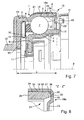
- the release bearing 1 is provided with the sealing cap 18e according to FIG. 7, whose legs 22 coincide with that shown in Figures 1 and 2 Match sealing cap 18a
- the seal between the outer bearing ring 3 and the sealing cap 18e is the cylindrical leg 19 of the sealing cap 18d on the inside in the area axially offset from the drawing stage 34
- Coating 35 is designed so that when the Sealing cap 18e at least partially scraped onto the outer bearing ring 3 is and collects in a ring zone 36, the outside of the cylindrical leg 19 and the radial leg 22 of the sealing cap 18d and inside of a chamfer 37 of the cylindrical portion 20 from outer bearing ring 3 is limited.
- the filled in by coating components Ring zone 36 optimizes the seal, which doubles as an extension the sealing zone 24 is to be designated
- an assembly tool 42 is preferably used for this purpose the bearing ring 3 with the flange 10 in a receptacle 43 of the assembly tool 42 inserted before the sealing cap 18e axially on the cylindrical Section 20 of the outer bearing 3 is pushed on, with at the same time the permanently elastic hardened sealing compound 25 is deformed and thereby fills the sealing zone 24.
- the sealing cap 18e is form-fitting on the bearing ring 3 attached in a position that takes into account the dimension for the functional gap 40
Landscapes
- Engineering & Computer Science (AREA)
- General Engineering & Computer Science (AREA)
- Mechanical Engineering (AREA)
- Rolling Contact Bearings (AREA)
- Sealing Of Bearings (AREA)
Abstract
Description
- Figur 1
- in einem Halbschnitt ein Ausrücklager, versehen mit einer erfindungsgemaßen Abdichtung,
- Figur 2
- in einer vergrößerten Darstellung die Einzelheit "X", gemäß Figur 1;
- Figur 3
- ein weitestgehend dem Ausrücklager gemäß Figur 1 vergleichbares Ausrücklager mit einer abweichend gestalteten Abdichtung;
- Figur 4
- in einer vergrößerten Abbildung die Einzelheit "Y", gemäß Figur 3,
- Figur 5
- in einer Einzelteilzeichnung eine Variante der erfindungsgemäßen Abdichtkappe,
- Figur 6
- eine weitere Variante der erfindungsgemäßen Abdichtkappe in einer Emzelteilzeichnung;
- Figur 7
- ein Ausrucklager in Verbindung mit einem Montagewerkzeug,
- Figur 8
- die Einzelheit "Z" der Figur 7, in einer vergrößerten Darstellung
- 1
- Ausrücklager
- 2
- Lagerring (innen)
- 3
- Lagerring (außen)
- 4
- Laufbahn
- 5
- Laufbahn
- 6
- Käfig
- 7
- Wälzkorper
- 8
- Längsachse
- 9
- Flansch
- 10
- Flansch
- 11
- Halteelement
- 12
- Tellerfeder
- 13
- Innenraum
- 14
- Abdichtung
- 15
- Abdichtung
- 16
- Ringspalt
- 17
- Ringspalt
- 18a
- Abdichtkappe
- 18b
- Abdichtkappe
- 18c
- Abdichtkappe
- 18d
- Abdichtkappe
- 18e
- Abdichtkappe
- 19
- Schenkel (zylindrisch)
- 20
- Abschnitt
- 21
- Bördelung
- 22
- Schenkel (radial)
- 23
- Durchsetzung
- 24
- Dichtzone
- 25
- Dichtmasse
- 26
- Dichtspalt
- 27
- Stirnseite
- 28
- Dichtfilm
- 29
- Nocken
- 30
- Dichtfilm
- 31
- Axialnut
- 32
- Steg
- 33
- Axialnut
- 34
- Ziehstufe
- 35
- Beschichtung
- 36
- Ringzone
- 37
- Fase
- 38
- Innenseite
- 39
- Spaltmaß
- 40
- Funktionsspalt
- 41
- Befestigungselement
- 42
- Montagewerkzeug
- 43
- Aufnahme
Claims (17)
- Ausrücklager für eine Betätigungseinrichtung von Schalttrennkupplungen, die in Fahrzeugen zwischen einer Brennkraftmaschine und einem Zahnräderwechselgetriebe eingesetzt ist, wobei das als ein Schrägschulterlager ausgebildete Ausrücklager (1) einen umlaufenden, äußeren Lagerring (3) und einen drehstarren inneren Lagerring (2) umfasst, zwischen denen in Laufbahnen (4, 5) geführte und in einem Käfig (6) eingesetzte Walzkörper (7) angeordnet sind, und zur Abdichtung eines Innenraums (13) des Ausrucklagers (1), Abdichtkappen (18a bis 18e) vorgesehen sind, die an einem Lagerring (2, 3) befestigt, unter Einhaltung eines Ringspaltes (16, 17) bis an den zugehörigen weiteren Lagerring (2, 3) geführt sind und jeder Lagerring (2, 3) einen rechtwinklig zu einer Längsachse (8) des Ausrücklagers (1) ausgerichteten Flansch (9, 10) aufweist, über den das Ausrücklager (1) an einem axial verschiebbaren Bauteil der Betatigungseinnchtung sowie einem Federmittel, insbesondere einer Tellerfeder (12) der Schalttrennkupplung abgestützt ist, dadurch gekennzeichnet, dass zur Abdichtung eines Dichtspaltes (26) zwischen dem äußeren Lagerring (3) und der an dem äußeren Lagerring (3) drehfixierten Abdichtkappe (18a bis 18e) eine flussig eingebrachte, dauerelastisch aushärtbare Dichtmasse (25) vorgesehen ist, die eine Dichtzone (24) der Abdichtkappe (18a bis 18e) ausfullt
- Ausrücklager nach Anspruch 1, dessen Abdichtkappe (18c, 18d) an dem von der Schaltrennkupplung abgewandten Seite des äußeren Lagerrings (3) angeordnet, mit einem zylindrischen Schenkel (19) den Lagerring (3) teilweise umschließt und deren in Richtung der Längsachse (8) ausgerichteter radialer Schenkel (22) eine Axialnut (31, 33) aufweist, die gemeinsam mit einer Stirnseite (27) des Lagerrings (3) den Dichtspalt (26) axial begrenzt.
- Ausrücklager nach Anspruch 1, wobei die spanlos, vorzugsweise durch ein Tiefziehen hergestellte Abdichtkappe (18a, 18b, 18e) mit einer an einem Endabschnitt des zylindrischen Schenkels (19) vorgesehenen Bordelung (21) formschlussig an dem Lagerring (3) befestigt ist
- Ausrucklager nach Anspruch 1, dessen Abdichtkappe (18b) an dem radialen Schenkel (22) in einer mit der Stirnseite (27) des Lagerrings (3) übereinstimmenden Lage symmetrisch umfangsverteilt angeordnete, axial in Richtung des Lagerrings (3) durchgestellte Nocken (29) aufweist.
- Ausrücklager nach Anspruch 1, dessen Abdichtkappe (18c) partiell eine symmetrisch umfangsverteilt angeordnete, dem Lagerring (3) entgegengesetzt ausgerichtete Axialnut (31) aufweist.
- Ausrücklager nach Anspruch 4, bei dem die axial ausgerichteten, zu einer Außenkontur der Abdichtkappe (18b) radial beabstandete Nocken (29) eine flächige Abstutzung der Abdichtkappe (18b) an der Stirnseite (27) des Lagerrings (3) vermeiden
- Ausrucklager nach Anspruch 4, wobei die Nocken (29) in einer Einbaulage der Abdichtkappe (18b)von der Dichtmasse (25) umschlossen und bis auf eine Starke eines Dichtfilms (30) an der Stirnseite (27) des äußeren Lagerrings (3) abgestutzt sind
- Ausrücklager nach Anspruch 1, wobei als Dichtmasse (25) ein hochtemperaturbeständiger Silikon-Kautschuk vorgesehen ist.
- Ausrücklager nach Anspruch 1, wobei die eingesetzte Dichtmasse (25) so bemessen ist, dass diese einen Überschuss bzw. einen Überstand zu den insbesondere radial verlaufenden Planflächen zwischen dem Lagerring (3) und der Abdichtkappe (18a bis 18e) im Bereich des Dichtspaltes (26) bildet.
- Ausrücklager nach Anspruch 1, bei dem das Dichtmittel, die dauerelastische Dichtmasse (25), sich zumindest begrenzt bis in ein Spaltmaß (39) erstreckt, das radial von dem äußeren Lagerring (3) und dem zylindrischen Schenkel (19) der Dichtkappe (18a bis 18e) begrenzt ist.
- Ausrücklager nach Anspruch 1, wobei die Abdichtkappe (18b) an einer Innenseite des zylindrischen Schenkels (19) eine radiale Ziehstufe (34) bildet, die einen spielfreien Einbau des zylindrischen Schenkels (19) an dem zylindrischen Abschnitt (20) der Abdichtkappe (18b, 18e) im eingebauten Zustand ermöglicht.
- Ausrücklager nach Anspruch 1, dessen Abdichtkappe (18e) an der Innenseite des zylindrischen Schenkels (19) eine Beschichtung (35) aufweist, die sich bei einem Zusammenbau der Abdichtkappe (18e) mit dem äußeren Lagerring (3) zumindest bereichsweise ablöst und die sich in einer von der Abdichtkappe (18e) und dem Lagerring (3) begrenzten Ringzone (36) sammelt.
- Ausrücklager nach Anspruch 12, bei dem der zylindrische Schenkel (19) innenseitig eine galvanische Beschichtung (35) aufweist, wie beispielsweise FeZn oder FeZnNi
- Ausrücklager nach Anspruch 12, bei dem die Abdichtkappe (18e) an der Innenseite des zylindrischen Schenkels (19) eine hochtemperaturbeständige Beschichtung (35) aus Kunststoff einschließt.
- Verfahren zur Abdichtung eines als ein Schrägschulterlager ausgebildeten Ausrücklagers (1), umfassend einen umlaufenden äußeren Lagerring (3) sowie einen drehstarren inneren Lagerring (2), zwischen denen Wälzkörper (7) angeordnet sind und zur Abdichtung eines Innenraums (13), das Ausrücklager (1) mit Abdichtkappen (18a bis 18e) versehen ist, die an einem Lagerring (2, 3) befestigt, unter Einhaltung eines Ringspaltes (16, 17) bis an dem zugehörigen weiteren Lagerring (2, 3) geführt sind, wobei zur Abdichtung eines Dichtspaltes (26) zwischen dem äußeren Lagerring (3) und der an dem Lagerring (3) drehfixierten Abdichtkappe (18a bis 18e) eine flüssig in die Abdichtkappe (18a bis 18e) eingebrachte Dichtmasse (25) vorgesehen ist, wobei die vor der Montage dauerelastisch aushärtbare Dichtmasse (25) sich bei der Montage verpresst.
- Verfahren nach Anspruch 15, wobei die Montage einen Funktionsspalt (40) zwischen der Abdichtkappe (18a bis 18e) und einem mit dem drehstarren Lagerung (2) verbundenen Befestigungselement (41) berücksichtigt und dazu die Abdichtkappe (18a bis 18e) mittels eines Montagewerkzeugs (42) auf Anschlag montierbar ist.
- Verfahren nach Anspruch 15, bei dem die Montage der Abdichtkappe (18a bis 18e) so erfolgt, dass sich ein Dichtfilm (28, 30) zwischen axial vorstehenden Nocken (29) oder Stegen (32) des radialen Schenkels (22) der Abdichtkappe (18b, 18d) und der Stirnseite (27) des Lagerrings (3) einstellt.
Applications Claiming Priority (2)
| Application Number | Priority Date | Filing Date | Title |
|---|---|---|---|
| DE10311207 | 2003-03-14 | ||
| DE10311207A DE10311207B4 (de) | 2003-03-14 | 2003-03-14 | Ausrücklager |
Publications (3)
| Publication Number | Publication Date |
|---|---|
| EP1457698A2 true EP1457698A2 (de) | 2004-09-15 |
| EP1457698A3 EP1457698A3 (de) | 2007-11-07 |
| EP1457698B1 EP1457698B1 (de) | 2012-11-28 |
Family
ID=32748248
Family Applications (1)
| Application Number | Title | Priority Date | Filing Date |
|---|---|---|---|
| EP04004936A Expired - Lifetime EP1457698B1 (de) | 2003-03-14 | 2004-03-03 | Ausrücklager |
Country Status (2)
| Country | Link |
|---|---|
| EP (1) | EP1457698B1 (de) |
| DE (1) | DE10311207B4 (de) |
Cited By (2)
| Publication number | Priority date | Publication date | Assignee | Title |
|---|---|---|---|---|
| FR2894000A1 (fr) * | 2005-11-25 | 2007-06-01 | Skf Ab | Procede de fabrication d'un palier a roulement, palier a roulement et butee axiale |
| US20150377292A1 (en) * | 2014-06-27 | 2015-12-31 | Aktiebolaget Skf | Bearing ring, method for manufacturing such a ring and bearing comprising such a ring |
Families Citing this family (5)
| Publication number | Priority date | Publication date | Assignee | Title |
|---|---|---|---|---|
| DE102005053612A1 (de) | 2005-11-10 | 2007-05-16 | Schaeffler Kg | Ausrücklager für eine Betätigungseinrichtung einer Schaltkupplung |
| DE102010010735A1 (de) | 2010-03-09 | 2011-09-15 | Schaeffler Technologies Gmbh & Co. Kg | Ausrücklager |
| DE102017105996A1 (de) | 2017-03-21 | 2018-09-27 | Schaeffler Technologies AG & Co. KG | Kupplungsausrücklager |
| DE102017107363A1 (de) | 2017-04-06 | 2018-10-11 | Schaeffler Technologies AG & Co. KG | Kupplungsausrücklager |
| DE102018101056A1 (de) | 2018-01-18 | 2019-07-18 | Schaeffler Technologies AG & Co. KG | Kupplungsausrücklager |
Citations (4)
| Publication number | Priority date | Publication date | Assignee | Title |
|---|---|---|---|---|
| DE9013580U1 (de) | 1989-10-02 | 1990-11-08 | Skf France, Clamart | Selbstzentrierendes Lager für ausrückbare Kupplungen |
| DE4425753A1 (de) | 1993-07-23 | 1995-01-26 | Skf France | Gezogener Kupplungsausrücker mit einem Verbindungsring und einem vorzentrierten Verbindungsglied sowie ein zugehöriges Montageverfahren |
| DE19622109A1 (de) | 1995-06-09 | 1996-12-12 | Skf France | Verbindungseinrichtung zwischen einem gezogenen Kupplungsausrücker und dessen Verbindungsring |
| DE19716218A1 (de) | 1997-04-18 | 1998-10-22 | Schaeffler Waelzlager Ohg | Kupplungsausrücklager |
Family Cites Families (2)
| Publication number | Priority date | Publication date | Assignee | Title |
|---|---|---|---|---|
| DE3709237A1 (de) * | 1987-03-20 | 1988-09-29 | Kugelfischer G Schaefer & Co | Schiebehuelse einer kfz-kupplung |
| FR2883347B1 (fr) * | 2005-03-15 | 2007-06-01 | Skf Ab | Butee de debrayage |
-
2003
- 2003-03-14 DE DE10311207A patent/DE10311207B4/de not_active Expired - Fee Related
-
2004
- 2004-03-03 EP EP04004936A patent/EP1457698B1/de not_active Expired - Lifetime
Patent Citations (4)
| Publication number | Priority date | Publication date | Assignee | Title |
|---|---|---|---|---|
| DE9013580U1 (de) | 1989-10-02 | 1990-11-08 | Skf France, Clamart | Selbstzentrierendes Lager für ausrückbare Kupplungen |
| DE4425753A1 (de) | 1993-07-23 | 1995-01-26 | Skf France | Gezogener Kupplungsausrücker mit einem Verbindungsring und einem vorzentrierten Verbindungsglied sowie ein zugehöriges Montageverfahren |
| DE19622109A1 (de) | 1995-06-09 | 1996-12-12 | Skf France | Verbindungseinrichtung zwischen einem gezogenen Kupplungsausrücker und dessen Verbindungsring |
| DE19716218A1 (de) | 1997-04-18 | 1998-10-22 | Schaeffler Waelzlager Ohg | Kupplungsausrücklager |
Cited By (3)
| Publication number | Priority date | Publication date | Assignee | Title |
|---|---|---|---|---|
| FR2894000A1 (fr) * | 2005-11-25 | 2007-06-01 | Skf Ab | Procede de fabrication d'un palier a roulement, palier a roulement et butee axiale |
| US20150377292A1 (en) * | 2014-06-27 | 2015-12-31 | Aktiebolaget Skf | Bearing ring, method for manufacturing such a ring and bearing comprising such a ring |
| US9677615B2 (en) * | 2014-06-27 | 2017-06-13 | Aktiebolaget Skf | Bearing ring, method for manufacturing such a ring and bearing comprising such a ring |
Also Published As
| Publication number | Publication date |
|---|---|
| DE10311207A1 (de) | 2004-09-23 |
| EP1457698B1 (de) | 2012-11-28 |
| EP1457698A3 (de) | 2007-11-07 |
| DE10311207B4 (de) | 2010-10-07 |
Similar Documents
| Publication | Publication Date | Title |
|---|---|---|
| DE3927589C2 (de) | Dichtungseinheit | |
| DE69612916T2 (de) | Hydraulisch betätigtes ausrücklager für kraftfahrzeugkupplung mit membranfeder | |
| DE102011006293B4 (de) | Stufenhülse, sowie hiermit gebildeter Pressverband | |
| DE19609472A1 (de) | Ringkolbendichtung für ein hydraulisch betätigbares Ausrücksystem | |
| DE10148388A1 (de) | Abdichtung für ein Wälzlager | |
| DE19716473C2 (de) | Zentralausrücker für eine hydraulische Kupplungsbetätigung | |
| WO1999064757A1 (de) | Führungshülse für einen nehmerzylinder | |
| DE10306926B4 (de) | Axiallager | |
| WO2003100260A2 (de) | Hydraulisches system insbesondere für kraftfahrzeuge | |
| DE102007046527B4 (de) | Lagereinheit | |
| DE19915975B4 (de) | Wälzlager | |
| DE102010010735A1 (de) | Ausrücklager | |
| EP1457698B1 (de) | Ausrücklager | |
| DE102005019474B4 (de) | Lageranordnung | |
| WO2005042992A1 (de) | Radiallagerung für eine antriebswelle von fahrzeugen | |
| DE10020640B4 (de) | Universalgelenk | |
| DE102009057331A1 (de) | Exzenter-Spannvorrichtung | |
| EP1125066A1 (de) | Dichtelement für ein ausrücklager | |
| DE19680050C1 (de) | Kupplungsausrücklagereinheit | |
| DE10208962A1 (de) | Vorrichtung zum Zentrieren eines Gelenkteils | |
| DE102009052759B4 (de) | Pressverband mit einem hülsenartigen Bauteil aus Blech | |
| DE102016222456B4 (de) | Fluidführungsbuchse, insbesondere für ein Kfz-Getriebe oder eine Kupplungseinrichtung | |
| DE10145751C1 (de) | Wälzlager und Verfahren zur Montage eines Wälzlagers | |
| DE102016211194A1 (de) | Werkzeug zum Einpressen eines Lagers | |
| DE102011087427B3 (de) | Maschinenanordnung |
Legal Events
| Date | Code | Title | Description |
|---|---|---|---|
| PUAI | Public reference made under article 153(3) epc to a published international application that has entered the european phase |
Free format text: ORIGINAL CODE: 0009012 |
|
| 17P | Request for examination filed |
Effective date: 20040303 |
|
| AK | Designated contracting states |
Kind code of ref document: A2 Designated state(s): AT BE BG CH CY CZ DE DK EE ES FI FR GB GR HU IE IT LI LU MC NL PL PT RO SE SI SK TR |
|
| AX | Request for extension of the european patent |
Extension state: AL LT LV MK |
|
| RAP1 | Party data changed (applicant data changed or rights of an application transferred) |
Owner name: SCHAEFFLER KG |
|
| PUAL | Search report despatched |
Free format text: ORIGINAL CODE: 0009013 |
|
| AK | Designated contracting states |
Kind code of ref document: A3 Designated state(s): AT BE BG CH CY CZ DE DK EE ES FI FR GB GR HU IE IT LI LU MC NL PL PT RO SE SI SK TR |
|
| AX | Request for extension of the european patent |
Extension state: AL LT LV MK |
|
| 17Q | First examination report despatched |
Effective date: 20080115 |
|
| AKX | Designation fees paid |
Designated state(s): CZ DE ES FR IT |
|
| RAP1 | Party data changed (applicant data changed or rights of an application transferred) |
Owner name: SCHAEFFLER TECHNOLOGIES AG & CO. KG |
|
| GRAP | Despatch of communication of intention to grant a patent |
Free format text: ORIGINAL CODE: EPIDOSNIGR1 |
|
| GRAS | Grant fee paid |
Free format text: ORIGINAL CODE: EPIDOSNIGR3 |
|
| GRAA | (expected) grant |
Free format text: ORIGINAL CODE: 0009210 |
|
| AK | Designated contracting states |
Kind code of ref document: B1 Designated state(s): CZ DE ES FR IT |
|
| REG | Reference to a national code |
Ref country code: DE Ref legal event code: R096 Ref document number: 502004013893 Country of ref document: DE Effective date: 20130124 |
|
| PG25 | Lapsed in a contracting state [announced via postgrant information from national office to epo] |
Ref country code: ES Free format text: LAPSE BECAUSE OF FAILURE TO SUBMIT A TRANSLATION OF THE DESCRIPTION OR TO PAY THE FEE WITHIN THE PRESCRIBED TIME-LIMIT Effective date: 20130311 |
|
| PG25 | Lapsed in a contracting state [announced via postgrant information from national office to epo] |
Ref country code: CZ Free format text: LAPSE BECAUSE OF FAILURE TO SUBMIT A TRANSLATION OF THE DESCRIPTION OR TO PAY THE FEE WITHIN THE PRESCRIBED TIME-LIMIT Effective date: 20121128 |
|
| PG25 | Lapsed in a contracting state [announced via postgrant information from national office to epo] |
Ref country code: IT Free format text: LAPSE BECAUSE OF FAILURE TO SUBMIT A TRANSLATION OF THE DESCRIPTION OR TO PAY THE FEE WITHIN THE PRESCRIBED TIME-LIMIT Effective date: 20121128 |
|
| PLBE | No opposition filed within time limit |
Free format text: ORIGINAL CODE: 0009261 |
|
| STAA | Information on the status of an ep patent application or granted ep patent |
Free format text: STATUS: NO OPPOSITION FILED WITHIN TIME LIMIT |
|
| 26N | No opposition filed |
Effective date: 20130829 |
|
| REG | Reference to a national code |
Ref country code: DE Ref legal event code: R097 Ref document number: 502004013893 Country of ref document: DE Effective date: 20130829 |
|
| REG | Reference to a national code |
Ref country code: DE Ref legal event code: R081 Ref document number: 502004013893 Country of ref document: DE Owner name: SCHAEFFLER TECHNOLOGIES GMBH & CO. KG, DE Free format text: FORMER OWNER: SCHAEFFLER TECHNOLOGIES AG & CO. KG, 91074 HERZOGENAURACH, DE Effective date: 20140218 Ref country code: DE Ref legal event code: R081 Ref document number: 502004013893 Country of ref document: DE Owner name: SCHAEFFLER TECHNOLOGIES AG & CO. KG, DE Free format text: FORMER OWNER: INA-SCHAEFFLER KG, 91074 HERZOGENAURACH, DE Effective date: 20121128 Ref country code: DE Ref legal event code: R081 Ref document number: 502004013893 Country of ref document: DE Owner name: SCHAEFFLER TECHNOLOGIES AG & CO. KG, DE Free format text: FORMER OWNER: SCHAEFFLER TECHNOLOGIES AG & CO. KG, 91074 HERZOGENAURACH, DE Effective date: 20140218 Ref country code: DE Ref legal event code: R081 Ref document number: 502004013893 Country of ref document: DE Owner name: SCHAEFFLER TECHNOLOGIES GMBH & CO. KG, DE Free format text: FORMER OWNER: INA-SCHAEFFLER KG, 91074 HERZOGENAURACH, DE Effective date: 20121128 |
|
| REG | Reference to a national code |
Ref country code: DE Ref legal event code: R081 Ref document number: 502004013893 Country of ref document: DE Owner name: SCHAEFFLER TECHNOLOGIES AG & CO. KG, DE Free format text: FORMER OWNER: SCHAEFFLER TECHNOLOGIES GMBH & CO. KG, 91074 HERZOGENAURACH, DE Effective date: 20150211 |
|
| REG | Reference to a national code |
Ref country code: FR Ref legal event code: PLFP Year of fee payment: 12 |
|
| REG | Reference to a national code |
Ref country code: FR Ref legal event code: PLFP Year of fee payment: 13 |
|
| REG | Reference to a national code |
Ref country code: FR Ref legal event code: PLFP Year of fee payment: 14 |
|
| REG | Reference to a national code |
Ref country code: FR Ref legal event code: PLFP Year of fee payment: 15 |
|
| PGFP | Annual fee paid to national office [announced via postgrant information from national office to epo] |
Ref country code: FR Payment date: 20200326 Year of fee payment: 17 |
|
| PGFP | Annual fee paid to national office [announced via postgrant information from national office to epo] |
Ref country code: DE Payment date: 20200528 Year of fee payment: 17 |
|
| REG | Reference to a national code |
Ref country code: DE Ref legal event code: R119 Ref document number: 502004013893 Country of ref document: DE |
|
| PG25 | Lapsed in a contracting state [announced via postgrant information from national office to epo] |
Ref country code: DE Free format text: LAPSE BECAUSE OF NON-PAYMENT OF DUE FEES Effective date: 20211001 Ref country code: FR Free format text: LAPSE BECAUSE OF NON-PAYMENT OF DUE FEES Effective date: 20210331 |
|
| P01 | Opt-out of the competence of the unified patent court (upc) registered |
Effective date: 20230523 |