EP1457298B1 - Ablegevorrichtung mit einem Drehteller für eine Aufschnittschneidemaschine - Google Patents
Ablegevorrichtung mit einem Drehteller für eine Aufschnittschneidemaschine Download PDFInfo
- Publication number
- EP1457298B1 EP1457298B1 EP04001510A EP04001510A EP1457298B1 EP 1457298 B1 EP1457298 B1 EP 1457298B1 EP 04001510 A EP04001510 A EP 04001510A EP 04001510 A EP04001510 A EP 04001510A EP 1457298 B1 EP1457298 B1 EP 1457298B1
- Authority
- EP
- European Patent Office
- Prior art keywords
- turntable
- rotary plate
- accordance
- depositing
- suction cup
- Prior art date
- Legal status (The legal status is an assumption and is not a legal conclusion. Google has not performed a legal analysis and makes no representation as to the accuracy of the status listed.)
- Expired - Lifetime
Links
Images

Classifications
-
- B—PERFORMING OPERATIONS; TRANSPORTING
- B25—HAND TOOLS; PORTABLE POWER-DRIVEN TOOLS; MANIPULATORS
- B25B—TOOLS OR BENCH DEVICES NOT OTHERWISE PROVIDED FOR, FOR FASTENING, CONNECTING, DISENGAGING, OR HOLDING
- B25B11/00—Work holders not covered by any preceding group in the subclass, e.g. magnetic work holders, vacuum work holders
- B25B11/005—Vacuum work holders
-
- B—PERFORMING OPERATIONS; TRANSPORTING
- B26—HAND CUTTING TOOLS; CUTTING; SEVERING
- B26D—CUTTING; DETAILS COMMON TO MACHINES FOR PERFORATING, PUNCHING, CUTTING-OUT, STAMPING-OUT OR SEVERING
- B26D7/00—Details of apparatus for cutting, cutting-out, stamping-out, punching, perforating, or severing by means other than cutting
- B26D7/27—Means for performing other operations combined with cutting
- B26D7/32—Means for performing other operations combined with cutting for conveying or stacking cut product
Definitions
- the invention relates to a depositing device for a slicing machine for depositing supplied by the cutting machine sliced shreds in fan-shaped on a deposit substrate, wherein the depositing device comprises a turntable for receiving the depositing substrate, a drive device for rotating the turntable by predetermined angular steps and a holding device, with the Deposit substrate rotatably on the turntable is fixed.
- Such a depositing device is known, for example, from AT 381 897 B.
- the problem with the depositing devices described above is that for filing the Thomasgutlismn in fan-shaped form of the turntable must be rotated after depositing a Thomasgutemia by a predetermined angle step before the next Thomasgutemia can be stored. Since the laying of the sliced slices on the depositing substrate is preferably carried out at a standstill of the turntable, the rotational steps of the turntable must be carried out jerkily, ie the turntable is briefly greatly accelerated and then braked again to a standstill.
- the AT 381 897 B proposes to provide slidable pins in the radial direction, which attack at a plate as a deposit substrate at the edge of the plate and set by the thus obtained frictional connection plate rotatably on the turntable.
- the flexible Ablegesubstrate here must be greater than the ultimately intended for occupancy with clippings surface, so that always a not inconsiderable edge of deposit substrate on the deposited cut out and this is also perforated, which may be aesthetically disadvantageous.
- the object of the present invention is to propose a depositing device for a slicing machine of the type described above, in which the rotationally fixed setting of the depositing substrate can be carried out in a simple manner, independently of the mechanical stability of the depositing substrate.
- the holding device comprises a centrally arranged on the turntable ventilatable suction cup, on which the depositing substrate can be placed and fixed.
- the laying device according to the invention has the advantage over the device known from AT 381 897 B in that no adjustment of the holding device to the size of the depositing substrate used is more necessary. Furthermore, in the case of flexible deposition substrates, it is not necessary to apply holes in the deposition substrate, and the deposition substrate can thus be coated to the edge and also be obtained from different sources, since a match of the hole pattern with retaining pins, as was necessary in the prior art, is here eliminated.
- the deposition substrate may have a larger diameter than the turntable itself, since the deposition substrate no longer has to be gripped on the edge in order to fix it rotationally on the turntable.
- the holding device of the depositing device according to the invention has only a single suction cup.
- the depositing substrate is released again and can be removed from the turntable.
- the suction cup is preferably held vertically adjustable on the turntable. This allows in a simple way flat substrates such as e.g. for this often used paper plates or flat plastic plates to set up and set the turntable.
- serving plates especially porcelain plates, which usually stand up on a downwardly projecting edge, with the turntable easy to connect, since then the suction cup only slightly upwards in height must be adjusted to still have a safe suction contact with the Make underside of the deposition substrate.
- the device has a turntable, which has a central depression, in which the suction cup is at least partially lowered.
- the turntable will have one or more concentric recesses with respect to the suction cup on its upper side receiving the depositing substrate, preferably corresponding to the standardized ones made of cardboard manufactured depositing substrates, so that they can be placed very easily centered on the turntable.
- these recesses can very well serve the centering of other non-standardized deposition substrates by giving the operator of the slicing machine an optical marking for a centered placement of the deposition substrate.
- the depositing device according to the invention is provided with a suction cup, which is ventilated by means of a spring-loaded valve, wherein preferably the spring holds the valve in the idle state in the closed position.
- an actuating element which is easily accessible below the turntable, is preferably provided, with which the spring-loaded valve can be brought into its ventilating position.
- the actuator will be a arranged below the turntable simple lever, especially in view of the fact that usually the depositing substrates are rotated at an occupancy with clippings by 360 °, so that, you begin the discard with a position of the turntable with forward, ie to the operator apportendem operating lever, the lever again forward to the user, when the deposition process is completed on the deposition substrate.
- the valve of the suction cup is designed as a check valve.
- the turntable preferably has one or more radially arranged slots, which are at least approximately finger-wide and extend to the outer circumference.
- a lever for venting the suction cup this will preferably be arranged between two radial slots.
- the turntable is pluggable connected to its drive device.
- the turntable can be easily removed and cleaned after completion of work with the cutting machine.
- the turntable is preferably made of a plastic material which is easy to clean.
- plastic materials are widely known and in particular so selectable that the turntable can be easily cleaned in conventional dishwashers without wear.
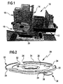
- FIG. 1 shows a slicing machine provided with the reference numeral 10 with a Thomasgutwagen 12, which is parallel to a cutting plane, which is defined by a rotating cutting blade 14, reciprocally movable.
- a conveyor 16 On the opposite side of the cutting blade 14, a conveyor 16 is arranged, which with a needle-shaped tips conveyor chain (not shown in detail) takes over the supplied from the slicing machine 10 slices of cuttings in the cutting plane and transported away from the cutting plane in a so-called tee position ,
- a laying device 18 In front of the conveying device 16, a laying device 18 according to the invention is arranged, on which a depositing substrate (not shown) can be positioned.
- the conveyor 16 When the slice of sliced meat arrives in the knock-down position of the conveyor, the conveyor 16 is abruptly moved forward with a so-called slicer (not shown) so that the sliced slice accelerates toward the slicing substrate, disengages from the conveyor 16 and then deposited on the slicing substrate becomes.
- the deposition substrate is positioned on a turntable 20 of the depositing device 18, which rotates after depositing a Thomasgutissue the rotary divider by a predetermined angle, so that then the deposition substrate ready for depositing another Thomasgutemia in fan-shaped on the deposition substrate.
- This process is usually repeated until the turntable 20 has rotated 360 ° and the deposition substrate is fully occupied.
- the deposit substrate is then removed from the turntable 20 and is ready for packaging or ready-to-serve with the shredded material placed thereon.
- the turntable 20 of the depositing device 18 is again shown in detail in a perspective view in FIG.
- the turntable 20 has a substantially circular shape, starting from the circumference of the turntable 20 starting radially inwardly extending, arranged at regular angular intervals four slots 24 are incorporated, which allow the positioned on the turntable depositing substrate easily with the fingers from below and can be lifted.
- the deposition substrate can be viewed from below, i. hygienic, are gripped, so that even with completely occupied deposition substrate detection of the deposited on the deposition substrate Thomasgutierin can be avoided.
- a suction cup 26 is provided, on which a deposit substrate can be pressed and thus rotatably connected via the suction of the suction cup 26 with the turntable 20.
- annular surfaces 28, 30, Concentric with the suction cup 26 are two successive annular surfaces 28, 30, of which the smaller diameter annular surface 28 is adjacent to the suction cup 26, to which the annular surface 30 connects radially outward with a step 32.
- the outer ring surface 30 is finally bounded by an upwardly projecting edge 34 which is interrupted at the locations where the slots 24 are arranged.
- the slots 24 preferably have such a radial extent that they extend into the inner annular surface 28 and thus also make it easy to grasp depositing substrates placed only on the inner annular surface 28.
- the outer diameters of the annular surfaces 28 and 30 are preferably chosen so that they fit standard discarding substrates made of cardboard so that they are easily centered within the step 32 or within the edge 34.
- the deposition substrate for example in the form of round cardboard plates
- the suction of the suction cup 26 and the cardboard plate (the deposition substrate) is rotatably connected to the turntable 20.
- the depositing substrate with the shredded substance deposited thereon is ready to accept.
- a mechanism is provided which actuates a spring-loaded valve (not shown in FIG. 2) for venting the suction cup 26 via a lever 36.
- the lever 36 is connected via a leaf spring 38 is biased vertically down, pushed up, the ventilation valve of the suction cup 26 is actuated and canceled the suction of the suction cup against the underside of the deposition substrate. The deposit substrate can then be easily picked up and lifted off the turntable 20.
- FIG 3 shows the turntable 20 in a view from below, in which case the lever mechanism is better visible.
- the lever 36 in this case extends almost to the middle of the turntable 20 and holds there, which will be described in more detail in connection with Figure 4, a valve closure element of the suction cup 26th
- the lever 36 is in this case held on a cylindrical fitting 40 on which the plate-shaped upper part of the turntable 20 is secured by bolts 42.
- the fitting 40 has three at equal angular intervals with respect to the center of the turntable 20 arranged holes 44, in the pins (not shown) of the drive device of the turntable 20 are used.
- the turntable 20 very simply rotatably put on the drive device of the depositing device and also remove it again, for example, to clean the turntable 20th
- FIG. 4 also shows in detail how the lever mechanism 36 can perform the ventilation of the suction cup 26.
- the lever 36 When the lever 36 is raised, its center-pointing end 46 tilts down about the pivot point located at the edge of the fitting 40 and removes a valve member 48 held at the end 46 from its valve seat 50 formed in the suction cup 26, thus allowing air into the space between the suction cup and more imposed Pour in the deposit substrate plate.
- the suction effect of the suction cup 26 is lifted relative to the underside of the depositing substrate and this can then be lifted freely from the turntable 20.
- the material of the turntable 20 is preferably a plastic material, in particular a plastic material that can be relatively easily cleaned in dishwashers without damage.
- a plastic material that can be relatively easily cleaned in dishwashers without damage.
- this can be made of a plastic material available on the market under the name Delrin from DuPont. This material has all the conditions that are necessary for a sufficient ease of cleaning.
- the fitting 40 is preferably made of stainless steel to ensure an exact fit of the holes 44 with the connecting pins on the side of the drive device of the depositing device.
Landscapes
- Engineering & Computer Science (AREA)
- Mechanical Engineering (AREA)
- Life Sciences & Earth Sciences (AREA)
- Forests & Forestry (AREA)
- Mechanical Treatment Of Semiconductor (AREA)
- Processing Of Stones Or Stones Resemblance Materials (AREA)
- Finish Polishing, Edge Sharpening, And Grinding By Specific Grinding Devices (AREA)
- Manufacturing Optical Record Carriers (AREA)
- Specific Conveyance Elements (AREA)
- Details Of Cutting Devices (AREA)
- Constituent Portions Of Griding Lathes, Driving, Sensing And Control (AREA)
Description
- Die Erfindung betrifft eine Ablegevorrichtung für eine Aufschnittschneidemaschine zum Ablegen von von der Schneidemaschine gelieferten Schnittgutscheiben in gefächerter Form auf einem Ablegesubstrat, wobei die Ablegevorrichtung einen Drehteller zur Aufnahme des Ablegesubstrates, eine Antriebsvorrichtung zum Drehen des Drehtellers um vorgegebene Winkelschritte und eine Haltevorrichtung umfasst, mit der das Ablegesubstrat drehfest am Drehteller festlegbar ist.
- Eine solche Ablegevorrichtung ist beispielsweise aus der AT 381 897 B bekannt. Das Problem bei den eingangs beschriebenen Ablegevorrichtungen besteht darin, dass zur Ablage der Schnittgutscheiben in gefächerter Form der Drehteller nach dem Ablegen einer Schnittgutscheibe um einen vorgegebenen Winkelschritt gedreht werden muss, bevor die nächste Schnittgutscheibe abgelegt werden kann. Da das Ablegen der Schnittgutscheiben auf dem Ablegesubstrat vorzugsweise bei einem Stillstand des Drehtellers vorgenommen wird, müssen die Drehschritte des Drehtellers ruckweise durchgeführt werden, d.h. der Drehteller wird kurz stark beschleunigt und dann wieder zum Stillstand abgebremst.
- Damit das Ablegesubstrat, das bei der ruckweisen Drehbewegung des Drehtellers Fliehkräften ausgesetzt ist, nicht von dem Drehteller abgeworfen wird, ist es notwendig, das Ablegesubstrat auf dem Drehteller zu halten.
- Hierzu schlägt die AT 381 897 B vor, in Radialrichtung verschiebliche Stifte vorzusehen, die bei einem Teller als Ablegesubstrat am Rand des Tellers angreifen und durch den so erzielten Kraftschluss den Teller drehfest auf dem Drehteller festlegen.
- Da dies nur bei Porzellantellem realisiert werden kann, die ausreichend mechanisch stabil sind, um den Kräften des Kraftschlusses zu widerstehen, wird für flexible Ablegesubstrate wie z.B. Pergamentpapier vorgeschlagen, die Ablegesubstrate mit einer Lochung zu versehen, so dass die Stifte durch die Löcher der flexiblen Ablegesubstrate hindurchgreifen können und so für eine drehfeste Anordnung des Ablegesubstrates gegenüber dem Drehteller sorgen.
- Nachteilig daran ist, dass zum einen bei der einen Ausführungsform der dort beschriebenen Ablegevorrichtung nur mechanisch sehr stabile Ablegesubstrate verwendet werden können und diese auch nur einen Radius aufweisen dürfen, der innerhalb des maximalen von den Haltestiften definierbaren Radius liegen muss. Bei der für flexible Ablegesubstrate entwickelten Betriebsstellung der Haltevorrichtung müssen zuvor die Haltestifte auf den Radius gebracht werden, in dem die Löcher in dem flexiblen Ablegesubstrat vorgesehen sind, des Weiteren muss das Ablegesubstrat gegenüber den Haltestiften justiert werden, da nur so eine drehfeste Fixierung des Ablegesubstrates möglich ist.
- Auch hier wiederum limitiert die Verfahrbarkeit der Stifte die mögliche Größe der Ablegesubstrate.
- Schließlich müssen die flexiblen Ablegesubstrate hier größer sein als die letztendlich zur Belegung mit Schnittgut vorgesehene Fläche, so dass stets ein nicht unbeträchtlicher Rand an Ablegesubstrat über das abgelegte Schnittgut hinaussteht und dieses zudem gelocht ist, was ästhetisch nachteilig sein kann.
- Aufgabe der vorliegenden Erfindung ist es, eine Ablegevorrichtung für eine Aufschnittschneidemaschine der eingangs beschriebenen Art vorzuschlagen, bei der das drehfeste Festlegen des Ablegesubstrates unabhängig von der mechanischen Stabilität des Ablegesubstrates in einfacher Weise vorgenommen werden kann.
- Diese Aufgabe wird erfindungsgemäß dadurch gelöst, dass die Haltevorrichtung einen zentral am Drehteller angeordneten belüftbaren Saugnapf umfasst, auf welchem das Ablegesubstrat aufsetzbar und festlegbar ist.
- Die erfindungsgemäße Ablegevorrichtung hat den Vorteil gegenüber der aus der AT 381 897 B bekannten Vorrichtung, dass kein Justieren der Haltevorrichtung auf die Größe des verwendeten Ablegesubstrates mehr notwendig ist. Ferner entfällt bei flexiblen Ablegesubstraten das Anbringen von Löchern in dem Ablegesubstrat, das Ablegesubstrat kann also bis an den Rand hin belegt werden und zudem aus unterschiedlichen Quellen bezogen werden, da eine Übereinstimmung des Lochmusters mit Haltestiften, wie dies beim Stand der Technik notwendig war, hier entfällt.
- Darüber hinaus kann das Ablegesubstrat einen größeren Durchmesser als der Drehteller selber aufweisen, da das Ablegesubstrat nicht mehr am Rand gegriffen werden muss, um dieses drehfest am Drehteller festzulegen.
- Um ein Ablegesubstrat gegenüber dem Drehteller festzulegen, ist es lediglich notwendig, das Ablegesubstrat auf dem Drehteller zu positionieren und leicht an dem Saugnapf anzudrücken. Der Saugnapf legt sich dann flexibel und unter Entlüften an der Unterseite des Ablegesubstrates an, ohne dass dabei Rücksicht genommen werden muss auf eine winkelgerechte Positionierung des Ablegesubstrates auf dem Drehteller.
- Bevorzugt weist die Haltevorrichtung der erfindungsgemäßen Ablegevorrichtung nur einen einzigen Saugnapf auf.
- Durch eine einfache Belüftung des Saugnapfes wird das Ablegesubstrat wieder freigegeben und ist von dem Drehteller abnehmbar.
- Um möglichst universal die Ablegevorrichtung mit vielerlei gängigen Ablegesubstraten betreiben zu können, wird der Saugnapf vorzugsweise höhenverstellbar am Drehteller gehalten. Dies erlaubt in einfacher Weise flache Substrate wie z.B. hierfür häufig verwendete Pappteller oder ebene Kunststoffplatten auf den Drehteller aufzusetzen und festzulegen.
- Andererseits sind auch Servierteller, insbesondere Porzellanteller, die in der Regel auf einem nach unten vorspringenden Rand aufstehen, mit dem Drehteller einfach zu verbinden, da dann der Saugnapf lediglich geringfügig nach oben in der Höhe verstellt werden muss, um trotzdem noch einen sicheren Saugkontakt mit der Unterseite des Ablegesubstrates herstellen zu können.
- Bevorzugt weist die Vorrichtung einen Drehteller auf, welcher eine mittige Vertiefung besitzt, in welcher der Saugnapf mindestens teilweise absenkbar ist.
- Dies lässt auch die Verwendung von leicht gewölbten Ablegesubstraten zu.
- Weiter bevorzugt wird der Drehteller an seiner das Ablegesubstrat aufnehmenden Oberseite bezüglich des Saugnapfes einen oder mehrere konzentrische Rücksprünge aufweisen, vorzugsweise entsprechend den standardisierten aus Pappe gefertigten Ablegesubstraten, so dass diese sehr einfach zentriert auf dem Drehteller aufgelegt werden können.
- Außerdem können diese Rücksprünge sehr gut der Zentrierung von anderen auch nicht-standardisierten Ablegesubstraten dienen, indem sie dem Bediener der Aufschnittschneidemaschine eine optische Markierung für ein zentriertes Aufsetzen des Ablegesubstrates geben.
- Es sei nur der Vollständigkeit halber darauf hingewiesen, dass mit der erfindungsgemäßen Ablegevorrichtung selbstverständlich nicht nur runde Ablegesubstrate verwendet werden können, sondern im Prinzip beliebig polygonal ausgebildete Ablegesubstrate, wobei lediglich sichergestellt werden muss, und dies gilt auch für den Durchmesser der kreisrunden Ablegesubstrate, dass der Drehteller gegenüber dem restlichen Maschinenaufbau der Schneidemaschine bei drehfest fixiertem Ablegesubstrat frei drehbar bleibt.
- Vorzugsweise ist die erfindungsgemäße Ablegevorrichtung mit einem Saugnapf versehen, welcher mittels eines federbelasteten Ventils belüftbar ist, wobei vorzugsweise die Feder das Ventil im Ruhezustand in Schließstellung hält.
- Zur Betätigung des federbelasteten Ventils wird vorzugsweise ein unterhalb des Drehtellers leicht zugängliches Betätigungselement vorgesehen, mit dem das federbelastete Ventil in seine Belüftungsstellung bringbar ist.
- Beispielsweise könnte hier ein ringförmiges Betätigungselement vorgesehen sein, was aber von den Fertigungskosten, insbesondere auch in Bezug auf den Fertigungsaufwand, anspruchsvoll ist. Bevorzugt wird deshalb das Betätigungselement ein unterhalb des Drehtellers angeordneter einfacher Hebel sein, insbesondere auch im Hinblick darauf, dass üblicherweise die Ablegesubstrate bei einer Belegung mit Schnittgut um 360° gedreht werden, so dass, beginnt man das Ablegen mit einer Stellung des Drehtellers mit nach vorn, d.h. zum Bediener hinweisendem Betätigungshebel, der Hebel wieder nach vorn zum Benutzer weist, wenn der Ablegevorgang auf dem Ablegesubstrat beendet ist.
- Zur Vereinfachung des Auflegens des Ablegesubstrates auf dem Saugnapf kann vorgesehen sein, dass das Ventil des Saugnapfes als Rückschlagventil ausgebildet ist. Um dem Bedienpersonal das Abnehmen des Ablegesubstrates zu erleichtem, wird vorzugsweise der Drehteller einen oder mehrere radial angeordnete, mindestens etwa fingerbreite, bis zum Außenumfang verlaufende Schlitze aufweisen.
- Wählt man als Betätigungselement einen Hebel zum Belüften des Saugnapfes, wird dieser bevorzugt zwischen zwei radialen Schlitzen angeordnet sein.
- Dies erlaubt den ungehinderten Zugang zu dem Ablegesubstrat durch die Schlitze, wobei der Hebel trotzdem gut zugänglich und bedienbar ist.
- Im Hinblick auf die Reinigungsfreundlichkeit der Ablegemaschine ist vorgesehen, dass der Drehteller steckbar mit seiner Antriebsvorrichtung verbindbar ist. Somit lässt sich der Drehteller nach Beendigung der Arbeit mit der Schneidemaschine einfach von dieser abnehmen und reinigen.
- Im Hinblick auf die Reinigungsfreundlichkeit, insbesondere aber auch im Hinblick auf das Minimieren der zu bewegenden Masse der Antriebsvorrichtung wird der Drehteller vorzugsweise aus einem Kunststoffmaterial, das leicht zu reinigen ist, gefertigt sein. Solche Kunststoffmaterialien sind vielfältig bekannt und insbesondere auch so auswählbar, dass der Drehteller einfach in üblichen Spülmaschinen ohne Verschleiß gereinigt werden kann.
- Diese und weitere Vorteile der Erfindung werden im Folgenden anhand der Zeichnungen noch näher erläutert. Es zeigen im Einzelnen:
- Figur 1:
- eine Aufschnittschneidemaschine mit einer erfindungsgemäßen Ablegevorrichtung;
- Figur 2:
- eine perspektivische Ansicht eines Drehtellers einer erfindungsgemäßen Ablegevorrichtung;
- Figur 3:
- eine Draufsicht auf die Unterseite des Drehtellers der Figur 2; und
- Figur 4:
- eine Schnittansicht längs Linie IV-IV in Figur 3.
- Figur 1 zeigt eine insgesamt mit dem Bezugszeichen 10 versehene Aufschnittschneidemaschine mit einem Schnittgutwagen 12, welcher parallel zu einer Schneidebene, die durch ein rotierendes Schneidmesser 14 definiert ist, hin und her bewegbar ist.
- Auf der gegenüberliegenden Seite des Schneidmessers 14 ist eine Fördervorrichtung 16 angeordnet, welche mit einer nadelförmige Spitzen aufweisenden Förderkette (im Einzelnen nicht gezeigt) die von der Aufschnittschneidemaschine 10 gelieferten Scheiben eines Schnittgutes im Bereich der Schneidebene übernimmt und von der Schneidebene weg in eine sogenannte Abschlagposition transportiert.
- Vor der Fördervorrichtung 16 ist eine erfindungsgemäße Ablegevorrichtung 18 angeordnet, auf welcher ein Ablegesubstrat (nicht dargestellt) positioniert werden kann.
- Kommt die Schnittgutscheibe in der Abschlagposition der Fördervorrichtung an, wird mit einem sogenannten Abschläger (nicht gezeigt) die Fördervorrichtung 16 schlagartig nach vorn bewegt, so dass die Schnittgutscheibe, in Richtung zum Ablegesubstrat beschleunigt, sich von der Fördervorrichtung 16 löst und dann auf dem Ablegesubstrat abgelegt wird. Das Ablegesubstrat ist dabei auf einem Drehteller 20 der Ablegevorrichtung 18 positioniert, die nach dem Ablegen einer Schnittgutscheibe den Drehteiler um einen vorgegebenen Winkel dreht, so dass dann das Ablegesubstrat für das Ablegen einer weiteren Schnittgutscheibe in gefächerter Form auf dem Ablegesubstrat bereitsteht.
- Dieser Vorgang wiederholt sich üblicherweise so oft, bis der Drehteller 20 eine Drehung um 360° vollführt hat und das Ablegesubstrat voll belegt ist.
- Das Ablegesubstrat wird dann von dem Drehteller 20 entnommen und ist mit dem darauf gefächert aufgelegten Schnittgut verpackungs- oder servierfertig.
- Zur Erläuterung der Erfindung ist in Figur 2 der Drehteller 20 der Ablegevorrichtung 18 in Einzelheiten nochmals in einer perspektivischen Darstellung gezeigt. Der Drehteller 20 hat eine im Wesentlichen kreisrunde Form, wobei vom Kreisumfang des Drehtellers 20 ausgehend radial nach innen verlaufende, in regelmäßigen Winkelabständen angeordnete vier Schlitze 24 eingearbeitet sind, die erlauben, dass das auf dem Drehteller positionierte Ablegesubstrat leicht mit den Fingern von unten gegriffen und abgehoben werden kann. Damit kann das Ablegesubstrat von unten, d.h. hygienisch einwandfrei, gegriffen werden, so dass auch bei vollständig belegtem Ablegesubstrat ein Erfassen der auf dem Ablegesubstrat abgelegten Schnittgutscheiben vermieden werden kann.
- In der Mitte des Drehtellers 20 ist ein Saugnapf 26 vorgesehen, auf den ein Ablegesubstrat aufgedrückt werden kann und damit über die Saugwirkung des Saugnapfes 26 drehfest mit dem Drehteller 20 verbunden werden kann.
- Konzentrisch zu dem Saugnapf 26 erstrecken sich zwei aufeinander folgende Ringflächen 28, 30, von denen die Ringfläche 28 mit kleinerem Durchmesser benachbart zum Saugnapf 26 angeordnet ist, an die sich die Ringfläche 30 mit einer Stufe 32 radial nach außen anschließt. Die äußere Ringfläche 30 wird schließlich von einem nach oben abstehenden Rand 34 begrenzt, welcher an den Stellen, an denen die Schlitze 24 angeordnet sind, unterbrochen ist.
- Die Schlitze 24 weisen bevorzugt eine solche Radialausdehnung auf, dass sie bis in die innere Ringfläche 28 reichen und so auch nur auf der inneren Ringfläche 28 aufgelegte Ablegesubstrate leicht greifbar machen.
- Die Außendurchmesser der Ringflächen 28 und 30 werden bevorzugt so gewählt, dass sie zu standardmäßig erhältliche Ablegesubstrate aus Pappe passen, so dass diese innerhalb der Stufe 32 bzw. innerhalb des Randes 34 leicht zentrierbar sind.
- Beim Auflegen des Ablegesubstrates, beispielsweise in Form von runden Pappplatten, brauchen diese nur innerhalb der Stufe 32 bzw. innerhalb des Randes 34 auf den Drehteller 20 aufgelegt und in der Mitte kurz auf dem Saugnapf 26 angedrückt werden. Sofort stellt sich die Saugwirkung des Saugnapfes 26 ein und die Pappplatte (das Ablegesubstrat) ist drehfest mit dem Drehteller 20 verbunden.
- Ist der Ablegevorgang für die Schnittgutscheiben auf dem Ablegesubstrat beendet, d.h. der Drehteller 20 hat in vorgegebenen Winkelschritten sich um 360° gedreht, ist das Ablegesubstrat mit dem darauf gefächert abgelegten Schnittgut abnahmebereit. Um das Ablegesubstrat nun von dem Drehteller 20 zu lösen, ist ein Mechanismus vorgesehen, welcher über einen Hebel 36 ein in der Figur 2 nicht dargestelltes federbelastetes Ventil zum Belüften des Saugnapfes 26 betätigt. Wird bei der vorliegenden Ausführungsform der Hebel 36, der über eine Blattfeder 38 vertikal nach unten vorgespannt wird, nach oben gedrückt, so wird das Belüftungsventil des Saugnapfes 26 betätigt und die Saugwirkung des Saugnapfes gegenüber der Unterseite des Ablegesubstrates aufgehoben. Das Ablegesubstrat kann dann problemlos von dem Drehteller 20 aufgenommen und abgehoben werden.
- Figur 3 zeigt den Drehteller 20 in einer Ansicht von unten, wobei hier der Hebelmechanismus besser sichtbar ist. Der Hebel 36 reicht hierbei bis fast in die Mitte des Drehtellers 20 und hält dort, was im Zusammenhang mit Figur 4 noch näher beschrieben werden wird, ein Ventilverschlusselement des Saugnapfes 26.
- Der Hebel 36 ist hierbei an einem zylindrischen Passstück 40 gehalten, auf dem das tellerförmige Oberteil des Drehtellers 20 über Schraubbolzen 42 befestigt ist. Das Passstück 40 weist drei in gleichen Winkelabständen bezüglich der Mitte des Drehtellers 20 angeordnete Bohrungen 44 auf, in die Stifte (nicht gezeigt) der Antriebsvorrichtung des Drehtellers 20 einsetzbar sind. Damit lässt sich der Drehteller 20 sehr einfach drehfest auf die Antriebsvorrichtung der Ablegevorrichtung aufsetzen und auch wieder abnehmen, beispielsweise zum Reinigen des Drehtellers 20.
- Ebenso wird aus den Figuren 3 und 4 ersichtlich, dass der Saugnapf 26 bei abgenommenem Drehteller 20 bei Verschleiß, d.h. beim Altern des Saugnapfmaterials, einfach abgenommen und durch einen neuen ersetzt werden kann.
- In Figur 4 ist schließlich auch noch im Einzelnen zu ersehen, wie der Hebelmechanismus 36 die Belüftung des Saugnapfes 26 durchführen kann. Bei einem Anheben des Hebels 36 kippt dessen zur Mitte hinweisendes Ende 46 um den am Rande des Passstückes 40 gelegenen Drehpunkt nach unten und entfernt ein am Ende 46 gehaltenes Ventilglied 48 aus seinem im Saugnapf 26 geformten Ventilsitz 50 und lässt so Luft in den Zwischenraum zwischen Saugnapf und aufgelegter Ablegesubstratplatte einströmen. Dadurch wird die Saugwirkung des Saugnapfes 26 gegenüber der Unterseite des Ablegesubstrates aufgehoben und dieses kann dann ungehindert von dem Drehteller 20 abgehoben werden.
- Das Material des Drehtellers 20 ist vorzugsweise ein Kunststoffmaterial, insbesondere ein Kunststoffmaterial, das relativ leicht auch in Spülmaschinen ohne Beschädigung gereinigt werden kann. Beispielsweise kann dies aus einem Kunststoffmaterial, das auf dem Markt unter dem Namen Delrin von DuPont angeboten wird, gefertigt werden. Dieses Material weist alle Voraussetzungen auf, die für eine ausreichende Reinigungsfreundlichkeit notwendig sind.
- Das Passstück 40 wird vorzugsweise aus Edelstahl gefertigt, um hier eine exakte Passung der Bohrungen 44 mit den Verbindungsstiften auf Seiten der Antriebsvorrichtung der Ablegevorrichtung sicherzustellen.
- Zum Entfernen des Saugnapfes 26 braucht lediglich eine Mutter 52 an dem nach unten abstehenden Zapfen 54 des Saugnapfes 26 entfernt werden, und der Saugnapf 26 kann nach oben abgezogen werden. Beim Einsetzen eines neuen Saugnapfes 26 muss dieser lediglich ausgerichtet auf das Ventilglied 48 auf den Drehteller aufgesetzt und von unten dann die Mutter 52 auf den nach unten durchragenden Zapfen 54 aufgeschraubt werden.
- Aus der schnittbildlichen Darstellung der Figur 4 ist leicht ersichtlich, dass nicht nur ebene Pappplatten mit der Ablegevorrichtung der vorliegenden Erfindung einfach fixiert werden können, sondern auch Porzellanteller oder dergleichen, da der Saugnapf 26 einfach in seiner Höhe, d.h. in dem Maß, in dem er über die Ringfläche 28 übersteht, angepasst werden kann.
Claims (10)
- Ablegevorrichtung für eine Aufschnittschneidemaschine zum Ablegen von von der Schneidemaschine gelieferten Schnittgutscheiben In gefächerter Form auf einem Ablegesubstrat, wobei die Ablegevorrichtung einen Drehteller zur Aufnahme des Ablegesubstrates, eine Antriebsvorrichtung zum Drehen des Drehtellers um vorgegebene Winkelschritte und eine Haltevorrichtung umfasst, mit der das Ablegesubstrat drehfest am Drehteller festlegbar ist, dadurch gekennzeichnet, dass die Haltevorrichtung einen zentral am Drehteller angeordneten belüftbaren flexiblen Saugnapf umfasst, auf welchem das Ablegesubstrat unter Entlüften aufsetzbar und festlegbar ist.
- Vorrichtung nach Anspruch 1, dadurch gekennzeichnet, dass die Haltevorrichtung einen einzigen Saugnapf umfasst.
- Vorrichtung nach Anspruch 1 oder 2, dadurch gekennzeichnet, dass der Drehteller eine mittige Vertiefung aufweist, in welcher der Saugnapf mindestens teilweise absenkbar ist.
- Vorrichtung nach einem der Ansprüche 1 bis 3, dadurch gekennzeichnet, dass der Drehteller an seiner das Ablegesubstrat aufnehmenden Oberseite zum Saugnapf konzentrisch angeordnet einen oder mehrere Rücksprünge und/oder abgestuft angeordnete Ringflächen aufweist.
- Vorrichtung nach einem der voranstehenden Ansprüche, dadurch gekennzeichnet, dass der Saugnapf mittels eines federbelasteten Ventils belüftbar ist, wobei die Feder das Ventil im Ruhezustand in Schließstellung hält.
- Vorrichtung nach Anspruch 5, dadurch gekennzeichnet, dass das federbelastete Ventil mittels eines unterhalb des Drehtellers angeordneten Betätigungselementes in seine Belüftungsstellung bringbar ist.
- Vorrichtung nach Anspruch 6, dadurch gekennzeichnet, dass das Betätigungselement ein unterhalb des Drehtellers angeordneter Hebel ist.
- Vorrichtung nach einem der voranstehenden Ansprüche, dadurch gekennzeichnet, dass der Drehteller einen oder mehrere radial angeordnete, mindestens etwa fingerbreite bis zum Außenumfang verlaufende Schlitze aufweist.
- Vorrichtung nach Anspruch 8, dadurch gekennzeichnet, dass der Hebel zwischen zwei radialen Schlitzen etwa mittig angeordnet ist.
- Vorrichtung nach einem der voranstehenden Ansprüche, dadurch gekennzeichnet, dass der Drehteller steckbar mit der Antriebsvorrichtung verbindbar ist.
Applications Claiming Priority (2)
| Application Number | Priority Date | Filing Date | Title |
|---|---|---|---|
| DE10311829A DE10311829A1 (de) | 2003-03-14 | 2003-03-14 | Ablegevorrichtung für eine Aufschnittschneidemaschine |
| DE10311829 | 2003-03-14 |
Publications (2)
| Publication Number | Publication Date |
|---|---|
| EP1457298A1 EP1457298A1 (de) | 2004-09-15 |
| EP1457298B1 true EP1457298B1 (de) | 2006-01-11 |
Family
ID=32748281
Family Applications (1)
| Application Number | Title | Priority Date | Filing Date |
|---|---|---|---|
| EP04001510A Expired - Lifetime EP1457298B1 (de) | 2003-03-14 | 2004-01-24 | Ablegevorrichtung mit einem Drehteller für eine Aufschnittschneidemaschine |
Country Status (3)
| Country | Link |
|---|---|
| EP (1) | EP1457298B1 (de) |
| AT (1) | ATE315459T1 (de) |
| DE (2) | DE10311829A1 (de) |
Cited By (2)
| Publication number | Priority date | Publication date | Assignee | Title |
|---|---|---|---|---|
| DE102009019430A1 (de) | 2009-04-29 | 2010-11-04 | Bizerba Gmbh & Co Kg | Umleger für automatische Scheibenschneidemaschinen |
| CN110774201A (zh) * | 2019-11-07 | 2020-02-11 | 中国航空制造技术研究院 | 一种用于飞机平垂尾固定的夹持装置 |
Family Cites Families (4)
| Publication number | Priority date | Publication date | Assignee | Title |
|---|---|---|---|---|
| US4131267A (en) * | 1978-06-02 | 1978-12-26 | Disco Kabushiki Kaisha | Apparatus for holding workpiece by suction |
| AT381897B (de) * | 1982-05-07 | 1986-12-10 | Kuchler Fritz | Rundteller der ablegeeinrichtung einer aufschnittschneidemaschine |
| DE4215546A1 (de) * | 1992-05-12 | 1993-11-18 | Dixie Union Verpackungen Gmbh | Vorrichtung zum Einlegen von Verpackungsgut in Mulden |
| US6483336B1 (en) * | 2000-05-03 | 2002-11-19 | Cascade Microtech, Inc. | Indexing rotatable chuck for a probe station |
-
2003
- 2003-03-14 DE DE10311829A patent/DE10311829A1/de not_active Withdrawn
-
2004
- 2004-01-24 AT AT04001510T patent/ATE315459T1/de active
- 2004-01-24 DE DE502004000233T patent/DE502004000233D1/de not_active Expired - Lifetime
- 2004-01-24 EP EP04001510A patent/EP1457298B1/de not_active Expired - Lifetime
Cited By (3)
| Publication number | Priority date | Publication date | Assignee | Title |
|---|---|---|---|---|
| DE102009019430A1 (de) | 2009-04-29 | 2010-11-04 | Bizerba Gmbh & Co Kg | Umleger für automatische Scheibenschneidemaschinen |
| CN110774201A (zh) * | 2019-11-07 | 2020-02-11 | 中国航空制造技术研究院 | 一种用于飞机平垂尾固定的夹持装置 |
| CN110774201B (zh) * | 2019-11-07 | 2021-07-27 | 中国航空制造技术研究院 | 一种用于飞机平垂尾固定的夹持装置 |
Also Published As
| Publication number | Publication date |
|---|---|
| DE502004000233D1 (de) | 2006-04-06 |
| DE10311829A1 (de) | 2004-09-23 |
| ATE315459T1 (de) | 2006-02-15 |
| EP1457298A1 (de) | 2004-09-15 |
Similar Documents
| Publication | Publication Date | Title |
|---|---|---|
| EP2628425B1 (de) | Elektromotorisch betriebene Küchenmaschine | |
| EP2815860B1 (de) | Vorrichtung zur schneidenden Bearbeitung von Material und Schneideinheit mit oszillierendem Schneidmesser und veränderlichem Schnittneigungswinkel | |
| DD295604A5 (de) | Vorrichtung zum Transportieren von Pilzen in Pilzzuchtbetrieben | |
| DE19826114C2 (de) | Pizzateilmaschine | |
| DE60303937T2 (de) | Schneidemaschine für lebensmittel | |
| EP2944441A1 (de) | Gemüsehobel | |
| WO2013110689A1 (de) | Vorrichtung zum schneiden und verpacken von brot | |
| EP1457298A1 (de) | Ablegevorrichtung mit einem Drehteller für eine Aufschnittschneidemaschine | |
| DE102007033922A1 (de) | Abstechvorrichtung zum Abheben von Lagen blattartiger Materialstapel | |
| DE102007046395A1 (de) | Ablage-Abtransportvorrichtung für Lebensmittel-Schnittgut und Lebensmittel-Schneidemaschine | |
| WO2014009460A1 (de) | Scheibenraffel | |
| WO2013110688A1 (de) | Schneidevorrichtung für brot | |
| DE10057835A1 (de) | Vorrichtung zum Schneiden von Lebensmitteln | |
| DE1043046B (de) | Wendeeinrichtung bei Vorrichtungen zur Knopfzufuehrung von Knopfannaehmaschinen | |
| EP2140988A2 (de) | Lebensmittel-Schneidemaschine und Verfahren zum Ablegen und Abtransportieren von Schnittgutscheiben | |
| DE19614125C2 (de) | Blechkuchenschneidemaschine | |
| WO2011054114A1 (de) | Einrichtung zum schaben von käselamellen von einem käsestück | |
| DE2847674A1 (de) | Vorrichtung zum aufbrechen organischer stoffe | |
| EP0536507A2 (de) | Vorrichtung zum Zerteilen eines Käselaibes | |
| DE102017109196A1 (de) | Scheibenschneidemaschine mit lösbar koppelbarer Ablageplatte | |
| AT409735B (de) | Aufschnittschneidemaschine | |
| EP1681141B1 (de) | Schneidemaschine für Lebensmittel | |
| EP1621062A1 (de) | Vorrichtung zum Ernten von Feldgemüse | |
| DE1923141C (de) | Vorrichtung zum Aufbereiten von Pikierkisten | |
| DE10311404A1 (de) | Vorrichtung für eine Schneidmaschine |
Legal Events
| Date | Code | Title | Description |
|---|---|---|---|
| PUAI | Public reference made under article 153(3) epc to a published international application that has entered the european phase |
Free format text: ORIGINAL CODE: 0009012 |
|
| AK | Designated contracting states |
Kind code of ref document: A1 Designated state(s): AT BE BG CH CY CZ DE DK EE ES FI FR GB GR HU IE IT LI LU MC NL PT RO SE SI SK TR |
|
| AX | Request for extension of the european patent |
Extension state: AL LT LV MK |
|
| 17P | Request for examination filed |
Effective date: 20050122 |
|
| 17Q | First examination report despatched |
Effective date: 20050314 |
|
| AKX | Designation fees paid |
Designated state(s): AT BE BG CH CY CZ DE DK EE ES FI FR GB GR HU IE IT LI LU MC NL PT RO SE SI SK TR |
|
| GRAP | Despatch of communication of intention to grant a patent |
Free format text: ORIGINAL CODE: EPIDOSNIGR1 |
|
| GRAS | Grant fee paid |
Free format text: ORIGINAL CODE: EPIDOSNIGR3 |
|
| GRAA | (expected) grant |
Free format text: ORIGINAL CODE: 0009210 |
|
| AK | Designated contracting states |
Kind code of ref document: B1 Designated state(s): AT BE BG CH CY CZ DE DK EE ES FI FR GB GR HU IE IT LI LU MC NL PT RO SE SI SK TR |
|
| PG25 | Lapsed in a contracting state [announced via postgrant information from national office to epo] |
Ref country code: SK Free format text: LAPSE BECAUSE OF FAILURE TO SUBMIT A TRANSLATION OF THE DESCRIPTION OR TO PAY THE FEE WITHIN THE PRESCRIBED TIME-LIMIT Effective date: 20060111 Ref country code: SI Free format text: LAPSE BECAUSE OF FAILURE TO SUBMIT A TRANSLATION OF THE DESCRIPTION OR TO PAY THE FEE WITHIN THE PRESCRIBED TIME-LIMIT Effective date: 20060111 Ref country code: RO Free format text: LAPSE BECAUSE OF FAILURE TO SUBMIT A TRANSLATION OF THE DESCRIPTION OR TO PAY THE FEE WITHIN THE PRESCRIBED TIME-LIMIT Effective date: 20060111 Ref country code: IE Free format text: LAPSE BECAUSE OF FAILURE TO SUBMIT A TRANSLATION OF THE DESCRIPTION OR TO PAY THE FEE WITHIN THE PRESCRIBED TIME-LIMIT Effective date: 20060111 Ref country code: GB Free format text: LAPSE BECAUSE OF FAILURE TO SUBMIT A TRANSLATION OF THE DESCRIPTION OR TO PAY THE FEE WITHIN THE PRESCRIBED TIME-LIMIT Effective date: 20060111 Ref country code: FI Free format text: LAPSE BECAUSE OF FAILURE TO SUBMIT A TRANSLATION OF THE DESCRIPTION OR TO PAY THE FEE WITHIN THE PRESCRIBED TIME-LIMIT Effective date: 20060111 |
|
| REG | Reference to a national code |
Ref country code: CH Ref legal event code: EP |
|
| PG25 | Lapsed in a contracting state [announced via postgrant information from national office to epo] |
Ref country code: MC Free format text: LAPSE BECAUSE OF NON-PAYMENT OF DUE FEES Effective date: 20060131 |
|
| REG | Reference to a national code |
Ref country code: IE Ref legal event code: FG4D Free format text: LANGUAGE OF EP DOCUMENT: GERMAN |
|
| PG25 | Lapsed in a contracting state [announced via postgrant information from national office to epo] |
Ref country code: LU Free format text: LAPSE BECAUSE OF NON-PAYMENT OF DUE FEES Effective date: 20060311 |
|
| REF | Corresponds to: |
Ref document number: 502004000233 Country of ref document: DE Date of ref document: 20060406 Kind code of ref document: P |
|
| PG25 | Lapsed in a contracting state [announced via postgrant information from national office to epo] |
Ref country code: SE Free format text: LAPSE BECAUSE OF FAILURE TO SUBMIT A TRANSLATION OF THE DESCRIPTION OR TO PAY THE FEE WITHIN THE PRESCRIBED TIME-LIMIT Effective date: 20060411 Ref country code: DK Free format text: LAPSE BECAUSE OF FAILURE TO SUBMIT A TRANSLATION OF THE DESCRIPTION OR TO PAY THE FEE WITHIN THE PRESCRIBED TIME-LIMIT Effective date: 20060411 Ref country code: BG Free format text: LAPSE BECAUSE OF FAILURE TO SUBMIT A TRANSLATION OF THE DESCRIPTION OR TO PAY THE FEE WITHIN THE PRESCRIBED TIME-LIMIT Effective date: 20060411 |
|
| PG25 | Lapsed in a contracting state [announced via postgrant information from national office to epo] |
Ref country code: ES Free format text: LAPSE BECAUSE OF FAILURE TO SUBMIT A TRANSLATION OF THE DESCRIPTION OR TO PAY THE FEE WITHIN THE PRESCRIBED TIME-LIMIT Effective date: 20060422 |
|
| REG | Reference to a national code |
Ref country code: CH Ref legal event code: NV Representative=s name: ISLER & PEDRAZZINI AG |
|
| PG25 | Lapsed in a contracting state [announced via postgrant information from national office to epo] |
Ref country code: PT Free format text: LAPSE BECAUSE OF FAILURE TO SUBMIT A TRANSLATION OF THE DESCRIPTION OR TO PAY THE FEE WITHIN THE PRESCRIBED TIME-LIMIT Effective date: 20060612 |
|
| GBV | Gb: ep patent (uk) treated as always having been void in accordance with gb section 77(7)/1977 [no translation filed] |
Effective date: 20060111 |
|
| REG | Reference to a national code |
Ref country code: IE Ref legal event code: FD4D |
|
| PLBE | No opposition filed within time limit |
Free format text: ORIGINAL CODE: 0009261 |
|
| STAA | Information on the status of an ep patent application or granted ep patent |
Free format text: STATUS: NO OPPOSITION FILED WITHIN TIME LIMIT |
|
| 26N | No opposition filed |
Effective date: 20061012 |
|
| EN | Fr: translation not filed | ||
| REG | Reference to a national code |
Ref country code: CH Ref legal event code: PCAR Free format text: ISLER & PEDRAZZINI AG;POSTFACH 1772;8027 ZUERICH (CH) |
|
| PG25 | Lapsed in a contracting state [announced via postgrant information from national office to epo] |
Ref country code: GR Free format text: LAPSE BECAUSE OF FAILURE TO SUBMIT A TRANSLATION OF THE DESCRIPTION OR TO PAY THE FEE WITHIN THE PRESCRIBED TIME-LIMIT Effective date: 20060412 Ref country code: FR Free format text: LAPSE BECAUSE OF FAILURE TO SUBMIT A TRANSLATION OF THE DESCRIPTION OR TO PAY THE FEE WITHIN THE PRESCRIBED TIME-LIMIT Effective date: 20070302 |
|
| PG25 | Lapsed in a contracting state [announced via postgrant information from national office to epo] |
Ref country code: EE Free format text: LAPSE BECAUSE OF FAILURE TO SUBMIT A TRANSLATION OF THE DESCRIPTION OR TO PAY THE FEE WITHIN THE PRESCRIBED TIME-LIMIT Effective date: 20060111 |
|
| PG25 | Lapsed in a contracting state [announced via postgrant information from national office to epo] |
Ref country code: TR Free format text: LAPSE BECAUSE OF FAILURE TO SUBMIT A TRANSLATION OF THE DESCRIPTION OR TO PAY THE FEE WITHIN THE PRESCRIBED TIME-LIMIT Effective date: 20060111 Ref country code: HU Free format text: LAPSE BECAUSE OF FAILURE TO SUBMIT A TRANSLATION OF THE DESCRIPTION OR TO PAY THE FEE WITHIN THE PRESCRIBED TIME-LIMIT Effective date: 20060712 |
|
| PG25 | Lapsed in a contracting state [announced via postgrant information from national office to epo] |
Ref country code: FR Free format text: LAPSE BECAUSE OF FAILURE TO SUBMIT A TRANSLATION OF THE DESCRIPTION OR TO PAY THE FEE WITHIN THE PRESCRIBED TIME-LIMIT Effective date: 20060131 |
|
| PG25 | Lapsed in a contracting state [announced via postgrant information from national office to epo] |
Ref country code: FR Free format text: LAPSE BECAUSE OF FAILURE TO SUBMIT A TRANSLATION OF THE DESCRIPTION OR TO PAY THE FEE WITHIN THE PRESCRIBED TIME-LIMIT Effective date: 20060111 Ref country code: CY Free format text: LAPSE BECAUSE OF FAILURE TO SUBMIT A TRANSLATION OF THE DESCRIPTION OR TO PAY THE FEE WITHIN THE PRESCRIBED TIME-LIMIT Effective date: 20060111 |
|
| PGFP | Annual fee paid to national office [announced via postgrant information from national office to epo] |
Ref country code: CZ Payment date: 20081029 Year of fee payment: 6 |
|
| PGFP | Annual fee paid to national office [announced via postgrant information from national office to epo] |
Ref country code: BE Payment date: 20081114 Year of fee payment: 6 |
|
| PGFP | Annual fee paid to national office [announced via postgrant information from national office to epo] |
Ref country code: CH Payment date: 20090130 Year of fee payment: 6 |
|
| BERE | Be: lapsed |
Owner name: *BIZERBA G.M.B.H. & CO. K.G. Effective date: 20100131 |
|
| REG | Reference to a national code |
Ref country code: CH Ref legal event code: PL |
|
| PG25 | Lapsed in a contracting state [announced via postgrant information from national office to epo] |
Ref country code: LI Free format text: LAPSE BECAUSE OF NON-PAYMENT OF DUE FEES Effective date: 20100131 Ref country code: CH Free format text: LAPSE BECAUSE OF NON-PAYMENT OF DUE FEES Effective date: 20100131 |
|
| PG25 | Lapsed in a contracting state [announced via postgrant information from national office to epo] |
Ref country code: CZ Free format text: LAPSE BECAUSE OF NON-PAYMENT OF DUE FEES Effective date: 20100124 |
|
| PG25 | Lapsed in a contracting state [announced via postgrant information from national office to epo] |
Ref country code: BE Free format text: LAPSE BECAUSE OF NON-PAYMENT OF DUE FEES Effective date: 20100131 |
|
| REG | Reference to a national code |
Ref country code: DE Ref legal event code: R082 Ref document number: 502004000233 Country of ref document: DE Representative=s name: HOEGER, STELLRECHT & PARTNER PATENTANWAELTE MB, DE |
|
| REG | Reference to a national code |
Ref country code: DE Ref legal event code: R082 Ref document number: 502004000233 Country of ref document: DE Representative=s name: HOEGER, STELLRECHT & PARTNER PATENTANWAELTE MB, DE Ref country code: DE Ref legal event code: R081 Ref document number: 502004000233 Country of ref document: DE Owner name: BIZERBA SE & CO. KG, DE Free format text: FORMER OWNER: BIZERBA GMBH & CO KG, 72336 BALINGEN, DE |
|
| PGFP | Annual fee paid to national office [announced via postgrant information from national office to epo] |
Ref country code: NL Payment date: 20180124 Year of fee payment: 15 |
|
| PGFP | Annual fee paid to national office [announced via postgrant information from national office to epo] |
Ref country code: AT Payment date: 20180122 Year of fee payment: 15 Ref country code: IT Payment date: 20180126 Year of fee payment: 15 |
|
| REG | Reference to a national code |
Ref country code: DE Ref legal event code: R082 Ref document number: 502004000233 Country of ref document: DE Representative=s name: HOEGER, STELLRECHT & PARTNER PATENTANWAELTE MB, DE |
|
| REG | Reference to a national code |
Ref country code: NL Ref legal event code: MM Effective date: 20190201 |
|
| REG | Reference to a national code |
Ref country code: AT Ref legal event code: MM01 Ref document number: 315459 Country of ref document: AT Kind code of ref document: T Effective date: 20190124 |
|
| PG25 | Lapsed in a contracting state [announced via postgrant information from national office to epo] |
Ref country code: NL Free format text: LAPSE BECAUSE OF NON-PAYMENT OF DUE FEES Effective date: 20190201 |
|
| PG25 | Lapsed in a contracting state [announced via postgrant information from national office to epo] |
Ref country code: AT Free format text: LAPSE BECAUSE OF NON-PAYMENT OF DUE FEES Effective date: 20190124 |
|
| PG25 | Lapsed in a contracting state [announced via postgrant information from national office to epo] |
Ref country code: IT Free format text: LAPSE BECAUSE OF NON-PAYMENT OF DUE FEES Effective date: 20190124 |
|
| PGFP | Annual fee paid to national office [announced via postgrant information from national office to epo] |
Ref country code: DE Payment date: 20200123 Year of fee payment: 17 |
|
| REG | Reference to a national code |
Ref country code: DE Ref legal event code: R119 Ref document number: 502004000233 Country of ref document: DE |
|
| PG25 | Lapsed in a contracting state [announced via postgrant information from national office to epo] |
Ref country code: DE Free format text: LAPSE BECAUSE OF NON-PAYMENT OF DUE FEES Effective date: 20210803 |